

Page 1
®
ENGINEERING COMPANY INC.
51 Winthrop Road
Chester, Connecticut 06412-0684
Epsilon™ Siren Amplifier
Installation Guide:
Phone: (860) 526-9504
Fax: (860) 526-4078
Internet: www.whelen.com
Sales e-mail: autosale@whelen.com
Canadian Sales e-mail: autocan@whelen.com
Customer Service e-mail: custserv@whelen.com
DANGER! Sirens produces extremely loud emergency warning tones! Exposure to these
tones without proper and adequate hearing protection, could cause ear damage and/or hearing
loss! The Occupational Safety & Health Administration (www.osha.gov) provides information
necessary to determine safe exposure times in Occupational Noise Exposure Section 1910.95.
Until you have determined the safe exposure times for your specific application, operators and
anyone else in the immediate vicinity should be required to wear an approved hearing protection
device. FAILURE TO FOLLOW THIS RECOMMENDATION COULD CAUSE HEARING LOSS!
Safety First
This document provides all the necessary information to allow your Whelen product to be properly and safely installed.
Before beginning the installation and/or operation of your new product, the installation technician and operator must
read this manual completely. Important information is contained herein that could prevent serious injury or damage.
• Proper installation of this product requires the installer to have a good understanding of automotive electronics,
systems and procedures.
• If mounting this product requires drilling holes, the installer MUST be sure that no vehicle components or other
vital parts could be damaged by the drilling process. Check both sides of the mounting surface before drilling
begins. Also de-burr any holes and remove any metal shards or remnants. Install grommets into all wire
passage holes.
• If this manual states that this product may be mounted with suction cups, magnets, tape or Velcro®, clean the
mounting surface with a 50/50 mix of isopropyl alcohol and water and dry thoroughly.
• Do not install this product or route any wires in the deployment area of your air bag. Equipment mounted or
located in the air bag deployment area will damage or reduce the effectiveness of the air bag, or become a
projectile that could cause serious personal injury or death. Refer to your vehicle owner’s manual for the air bag
deployment area. The User/Installer assumes full responsibility to determine proper mounting location, based
on providing ultimate safety to all passengers inside the vehicle.
• For this product to operate at optimum efficiency, a good electrical connection to chassis ground must be
made. The recommended procedure requires the product ground wire to be connected directly to the NEGATIVE
(-) battery post.
• If this product uses a remote device to activate or control this product, make sure this control is located in an
area that allows both the vehicle and the control to be operated safely in any driving condition. DO NOT
ATTEMPT TO ACTIVATE OR CONTROL THIS DEVICE IN A HAZARDOUS DRIVING SITUATION.
• It is recommended that these instructions be stored in a safe place and
referred to when performing maintenance and/or reinstallation of this
product.
• FAILURE TO FOLLOW THESE SAFETY PRECAUTIONS AND
INSTRUCTIONS COULD RESULT IN DAMAGE TO THE PRODUCT OR
VEHICLE AND/OR SERIOUS INJURY TO YOU AND YOUR PASSENGERS!
ACTIVATION OF THIS
SIREN MAY DAMAGE
UNPROTECTED EARS!
CAUTION
Loud siren noise can cause
hearing damage and/or loss.
Wear
Refer to OSHA Section 1910.95 prior
Protection!
to putting ANY siren into service!
Automotive: Sirens/Switches
For warranty information regarding this product, visit www.whelen.com/warranty
©2008 Whelen Engineering Company Inc.
Form No.14218 (101508)
Page 1
Page 2
Congratulations on selecting the Epsilon™ Siren. This siren offers a unique and distinctive collection of features designed to allow the
user to customize the operation of this siren to suit their individual needs. Features include:
• Speaker diagnostic indicator
• 100 watts of output power
• Scan-Lock™ siren tone programming
• Hands-Free operation
• LED Backlighting
• 7 position rotary switch function selector
• Compact design
• Harmonically rich composite air horn tones
Mounting:
This siren is designed to be mounted directly onto the dash or other surface through
the use of a bail strap mounting bracket. The unit may also be mounted into your
vehicle’s console (if so equipped).
WARNING: Regardless of the style selected, be sure to observe the Air Bag
Warning on the cover of this manual.
WARNING: Mounting this unit will require drilling. It is absolutely necessary to
make sure that no other vehicle components could be damaged in the process.
Check both sides of the mounting surface before starting. If damage is likely,
select a different location.
Bail Strap Mount:
1. Position bail strap in selected mounting
location and drill mounting holes, then
secure the bail strap to the vehicle.
2. Secure the siren to the bail strap as shown.
Tighten the screws firmly.
®
Console Mount:
Console manufacturers offer mounting kits that include all the necessary hardware
and brackets required to mount this unit into their console. The console mount
brackets are secured onto the unit the same way as the bail bracket. Please refer to
the manual included with your console.
Microphone Clip:
A microphone clip is included. Secure with provided hardware.
WARNING: Refer to the Air Bag Warning before installing this clip.
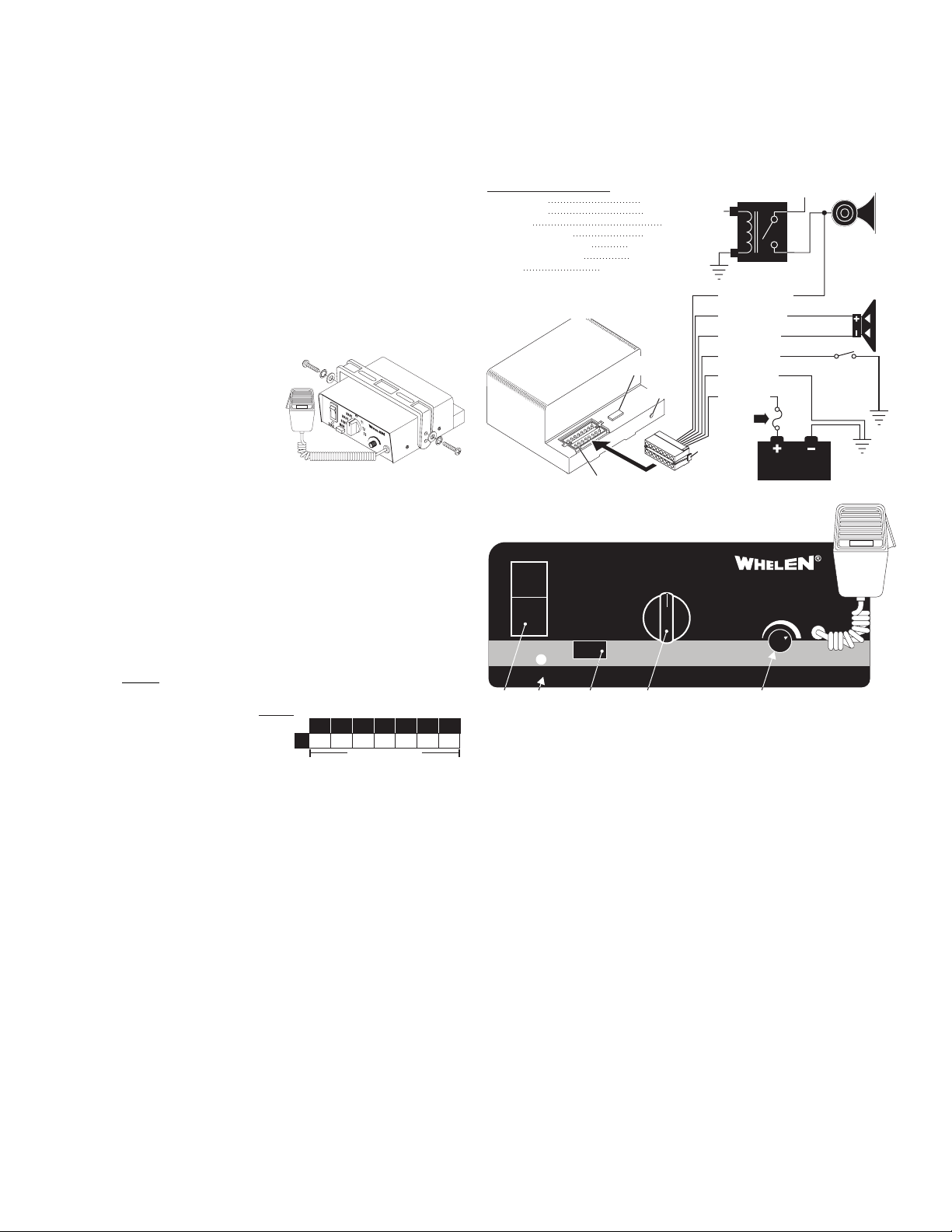
Wiring:
Siren Input Connector - RED: Power - BLACK: Ground
WARNING: All customer supplied wires that connect to the positive terminal of
the battery must be sized to supply at least 125% of the maximum operating
current and FUSED
BREAKERS WITH THIS PRODUCT!
1. Extend the RED and BLACK wires
toward the vehicle battery. To pass
the RED and BLACK wires
through, you may have to drill a
hole in the firewall. Insert a grommet to protect the wires.
2. Route the RED and BLACK wires along the factory harness towards the battery
and install a fuse block (user supplied) on the end of the RED wire. Remove fuse
from fuse block before connecting any wires to battery.
3. Connect fuse block wire to POSITIVE terminal on battery. There must not be more
than 2 feet of wire between fuse block and battery. The wire between the fuse and
battery is “unprotected,” do not allow it to chafe and short to ground.
4. Connect the BLACK wire to the factory chassis ground.
YELLOW & BROWN - Speaker Wires
1. Route the YELLOW and BROWN wires toward vehicle siren speakers, along
factory wire harness and through firewall at the same point as the RED and
BLACK wires.
2. Connect the YELLOW wire to the POSITIVE terminal on the SPEAKER and the
BROWN wire to NEGATIVE connection on the speaker.
WHITE/GREEN - Horn Relay Wires:
1. Route WHITE/GREEN wire along factory wire harness and through firewall at the
same point as the RED and BLACK wires.
2. Route WHITE/GREEN wires to vehicle’s horn relay. If possible, follow the factory
wire harness to this relay.
3. Locate the wire that connects the vehicle horn to the horn relay.
4. Connect the WHITE/GREEN wire to the wire that runs from the horn relay to the
horn.
GREEN - Aux Override:
This wire is activated by switching it to ground (see page 3 for operation).
at the battery to carry that load. DO NOT USE CIRCUIT
TABLE 1
Current Draw
AMPS
Wire Gauge / AWG
20
22
5
3
Distance in Feet
18
16
14 12
7.51219.5
10
49
3110
• Title 13 compliant profiles
• Non-destructive short circuit protection.
• Horn ring control inputs
•PA Override
HORN
WIRING DIAGRAM
INPUT VOLTAGE
INPUT CURRENT
INPUT FUSE
SPEAKER IMPEDANCE
OPERATING TEMPERATURE
STORAGE TEMPERATURE
HUMIDITY
OUTPUT VOLTAGE
OUTPUT POWER
Unused Outlets:2-3-5-7-8-9-10
@ 15 VDC @ 11 OHMS 34 V RMS MAX.
@ 15 VDC @ 11 OHMS 105 WATTS MAX.
13-14&16Unused Outlets:
Rear view
of amplifier
12.8 VDC ±20%
8 AMPS MAX.
10 AMPS
11 OHMS MIN.
-30° C. TO +60° C.
-40° C. TO +70° C.
99% (NON CONDENSING)
10 Amp
Fuse
Scan-Lock™
16 Position
Outlet
TO HORN
BUTTON
RELAY
+12V
11
WHT/GRN
6
YELLOW
4
BROWN
GREEN
12
1
BLACK
RED15
1
0 AMP
FUSE
16 Position
Connector
Fuses & Fuse Blocks are customer supplied.
BATTERY
AUXILIARY
OVERRIDE
CONNECTION
(OPTIONAL)
CHASSIS
GROUND
Front Panel
POWER
MAN1
STDBY
MAN
SPKR
Power
Switch
Diagnostic
Indicator
Manual
Button
Power Switch
This switch has two positions. Down (Off) and Up (On). When this switch is off, siren
functions are disabled.
Rotary Switch
The Rotary Knob controls the siren functions of the Epsilon. There are 7 positions
that may be selected (see “Switch Operations”).
Volume Knob
The Volume Knob controls the volume of Public Address function. Volume is
increased by rotating the knob in a clockwise direction. Rotating the volume knob in a
counter-clockwise direction decreases the volume produced by these features. The
volume knob has no effect on siren tones.
MAN Button
The Manual button generates a variety of tones, depending on what position the
rotary knob is in (see “Switch Operations”).
Diagnostic Indicator:
While this siren is under normal use the diagnostic indicator is used to indicate fault
conditions with your siren system. The following table lists the type of fault and the
indicators response. If the indicator is on steady while a tone is in use, this implies
that there is no fault with the speaker output.
Fault Condition Diagnostic Indicators Response
Speaker Short Circuit: The speaker LED will be in a SingleFlash mode (the LED will
be on and off an equal amount of time) and siren tones won’t operate.
Speaker Undercurrent: Speaker LED will be off. All tones will continue to operate.
Microphone:
Whenever the siren is on, activating the microphone (pressing the switch on the side
of the mic.) will shut down any other siren functions and enable public address
operation regardless of the rotary switch position or any other switch or input.
MAN2
Rotary
Switch
HF
T1
T2
T3
VOL
Microphone
Volume
HORN
VEHICLE
100W
SPEAKER
Page 2
Page 3

Rotary Switch Operations:
This section will outline the operation of the siren in the factory default
configuration. Refer to “Programming the Epsilon™ Siren”) for
information on how to customize the operation of this siren.
STDBY - Stand-by: When the rotary switch is in this position the siren
is in standby. No tones will be activated until another action is taken by the
operator.
With the Rotary Switch in this Position:
Pressing the MAN button or activating either the HORN RING or AUX
OVERRIDE input will produce the AIRHORN tone. The AIRHORN tone
will stop when the input is released.
Programming the Epsilon™ Siren:
Siren Tone Programing Procedures
With Scan-Lock™ the tonal operation of the siren can be customized
to fit your needs. Scan-Lock is used to change the default siren
tones as shown below.
To change the primary tone for rotary switch
positions T1, T2, & T3: Put the rotary switch in
the position that you wish to change. Press and
release the Scan-Lock switch. Each time the
Scan-Lock switch is pressed and released, the
next available tone will be broadcast. When the
desired tone is generated, it is automatically
saved for that rotary switch position.
TABLE 3
Positions T1, T2 & T3
.
TONE OFF
.
WAIL
.
YELP
= Title 13 Compliant Tones
*
*
yTone List For Rotar Switch
.
HI/LOW
.
PIERCER
.
Y-249
MAN 1 - Manual Siren #1: When the rotary switch is in this position
the siren is in standby. No tones will be activated until an action is taken by
the operator.
With the Rotary Switch in this Position:
Pressing the MAN button or activating either the AUX ENABLE or HORN
RING input will produce a WAIL tone. The WAIL tone will ramp up to peak
frequency, then ramp back down and stop when the input is released.
MAN 2 - Manual Siren #2: When the rotary switch is in this position
the siren is in standby. No tones will be activated until an action is taken by
the operator.
With the Rotary Switch in this Position:
Pressing the MAN switch or activating either the HORN RING or AUX
OVERRIDE input will produce a WAIL tone. This tone will ramp up to peak
frequency and stop when the input is released.
HF - Hands-Free Operation - When the rotary knob is in the HF
position, the siren functions are placed in a stand-by mode. Siren tones
are activated by a single “tap” on the MAN button or the vehicle’s steering
wheel horn ring (if the vehicle’s horn has been wired to the HORN RING
input). The first tap produces a “Wail” tone (a steady rise and fall tone). A
second tap produces a “Yelp” tone (a fast rise and fall tone). A third tap
produces a “Piercer™” tone (an extremely fast rise and fall tone). The next
tap returns the siren to a wail tone and the cycle repeats itself. Two quick
successive taps will stop the siren.
With the Rotary Switch in this Position:
Pressing the MAN button or activating either the HORN RING or AUX
OVERRIDE input will produce the HF cycle.
T1 - Tone #1: When the rotary knob is in the T1 position, a steady, rise
and fall tone (WAIL) is produced.
With the Rotary Switch in this Position:
Pressing the MAN button or activating either the HORN RING or AUX
OVERRIDE will change the siren tone to a YELP pattern (a fast rise and
fall tone). Activating the input a second time returns the tone back to
WAIL .
To change the override tone for rotary switch
positions T1, T2. & T3: Put the rotary switch in
the position that you wish to change. Press and
hold the MAN button on the front panel on the
siren. Press and release the Scan-Lock switch.
Each time the Scan-Lock switch is pressed and
released, the next available tone will be
broadcast. When the desired tone is present, it
will automatically be saved as the override tone for that rotary switch
position. Release the MAN button.
To change one of the tones in the hands free
cycle. (See “Hands-Free Operation”): Put the
rotary switch in the HF position. Using the MAN
button on the front panel on the siren, advance to
the tone that you wish to change. Press and
release the Scan-Lock switch. Each time the
Scan-Lock switch is pressed and released, the
next available tone will be broadcast. When the desired tone is generated,
it will automatically be saved for that hands-free cycle position.
To change the tone for rotary switch positions
MAN1 or MAN2:
Put the rotary switch in the position that you wish
to change. Press and hold the MAN button on the
front panel on the siren. Press and release the
Scan-Lock switch. Each time the Scan-Lock
switch is pressed and released, the next available tone will be broadcast.
When the desired tone is generated, it will automatically be saved for that
rotary switch position. Release the MAN button.
To change the override tone for rotary switch
position STDBY:
Put the rotary switch in the STDBY position.
Press and hold the MAN button on the front panel
on the siren. Press and release the Scan-Lock
switch. Each time Scan-Lock is pressed and
released, the next available tone will be broadcast. When the desired tone
is generated, it will automatically be saved for that rotary switch position.
Release the MAN button.
TABLE 4
Override Tone List For Rotar
Switch Positions T1, T2 & T3
.
TONE OFF
.
WAIL
.
YELP
.
AIRHORN
= Title 13 Compliant Tones
*
*
TABLE 5
Tone List For Hands Free:
.
WAIL
.
YELP
.
PIERCER
= Title 13 Compliant Tones
*
*
TABLE 6
Tone List For MAN1 & MAN2:
.
TONE OFF
.
MANUAL WAIL COAST-TO-STOP
M
.
MANUAL WAIL STOP
TABLE 7
Override Tone List For Rotary
Switch Position STBY and the
HORN button:
TONE OFF.AIRHORN
.
HI/LOW
.
PIERCER
.
Y-249
.
PIERCER
.
Y-249
.
HI/LOW
.
y
T2 - Tone #2: When the rotary knob is in the T2 position, a fast, rise and
fall tone (YELP) is produced.
With the Rotary Switch in this Position:
Pressing the MAN button or activating either the HORN RING or AUX
OVERRIDE input will produce the PIERCER tone. Pressing the MAN
button a second time returns it back to YELP.
T3 - Tone #3: When the rotary knob is in the T3 position, an extremely
fast, rise and fall tone is produced.
With the Rotary Switch in this Position:
Pressing the MAN button or activating the HORN RING or AUX OVERRIDE input will result in the AIRHORN tone until the input is released.
Title 13 Operation:
Airhorn will not override primary tones. To put the siren into Title 13
operation mode:
1. Turn the POWER switch OFF.
3. Place the ROTARY SWITCH into the MAN1 position.
4. Hold Scan-Lock switch in while turning power on. A set
of Title 13 compliant tones have been programmed for use.
Turn power off, then on to activate changes.
Re-Setting Factory Defaults:
To restore siren tones to the factory defaults:
1. Turn the POWER switch OFF.
3. Place the ROTARY SWITCH into the MAN2 position.
4. Hold Scan-Lock switch in while turning power on.
Turn power off, then back on to activate the changes.
Page 3
 Loading...