

Page 1

®
ENGINEERING COMPANY INC.
51 Winthrop Road
Chester, Connecticut 06412-0684
DOT-LED® All LED DOT System
Installation Guide:
Phone: (860) 526-9504
Fax: (860) 526-4078
Internet: www.whelen.com
Sales e-mail: autosale@whelen.com
Canadian Sales e-mail: canadiansales@whelen.com
Customer Service e-mail: custserv@whelen.com
Safety First
This document provides all the necessary information to allow your Whelen product to be properly and safely installed.
Before beginning the installation and/or operation of your new product, the installation technician and operator must
read this manual completely. Important information is contained herein that could prevent serious injury or damage.
• Proper installation of this product requires the installer to have a good understanding of automotive electronics,
systems and procedures.
• Failure to use specified installation parts and/or hardware will void the product warranty!
• If mounting this product requires drilling holes, the installer MUST be sure that no vehicle components or other
vital parts could be damaged by the drilling process. Check both sides of the mounting surface before drilling
begins. Also de-burr any holes and remove any metal shards or remnants. Install grommets into all wire
passage holes.
• If this manual states that this product may be mounted with suction cups, magnets, tape or Velcro®, clean the
mounting surface with a 50/50 mix of isopropyl alcohol and water and dry thoroughly.
• Do not install this product or route any wires in the deployment area of your air bag. Equipment mounted or
located in the air bag deployment area will damage or reduce the effectiveness of the air bag, or become a
projectile that could cause serious personal injury or death. Refer to your vehicle owner’s manual for the air bag
deployment area. The User/Installer assumes full responsibility to determine proper mounting location, based
on providing ultimate safety to all passengers inside the vehicle.
• For this product to operate at optimum efficiency, a good electrical connection to chassis ground must be
made. The recommended procedure requires the product ground wire to be connected directly to the NEGATIVE
(-) battery post.
• If this product uses a remote device to activate or control this product, make sure that this control is located in
an area that allows both the vehicle and the control to be operated safely in any driving condition.
• Do not attempt to activate or control this device in a hazardous driving situation.
• If this product contains strobe light(s), halogen light(s) or high-intensity LEDs, do not stare directly into these
lights at a close distance. Momentary blindness and/or eye damage could result.
• Use only soap and water to clean the outer lens. Use of other chemicals could result in premature lens cracking
(crazing) and discoloration. Lens in this condition have significantly reduced effectiveness and should be
replaced immediately. Inspect and operate this product regularly to confirm its proper operation and mounting
condition. Do not use a pressure washer to clean this product.
• It is recommended that these instructions be stored in a safe place and referred to when performing
maintenance and/or reinstallation of this product.
• FAILURE TO FOLLOW THESE SAFETY PRECAUTIONS AND INSTRUCTIONS COULD RESULT IN DAMAGE TO
THE PRODUCT OR VEHICLE AND/OR SERIOUS INJURY TO YOU AND YOUR PASSENGERS!
Automotive: DOT
For warranty information regarding this product, visit www.whelen.com/warranty
©2003 Whelen Engineering Company Inc.
Form No.13861G (110812)
Page 1
Page 2
CAUTION! DO NOT LOOK DIRECTLY AT
THESE LED’S WHILE THEY ARE ON.
MOMENTAR Y BLINDNESS AND/OR EYE
DAMAGE COULD RESULT!
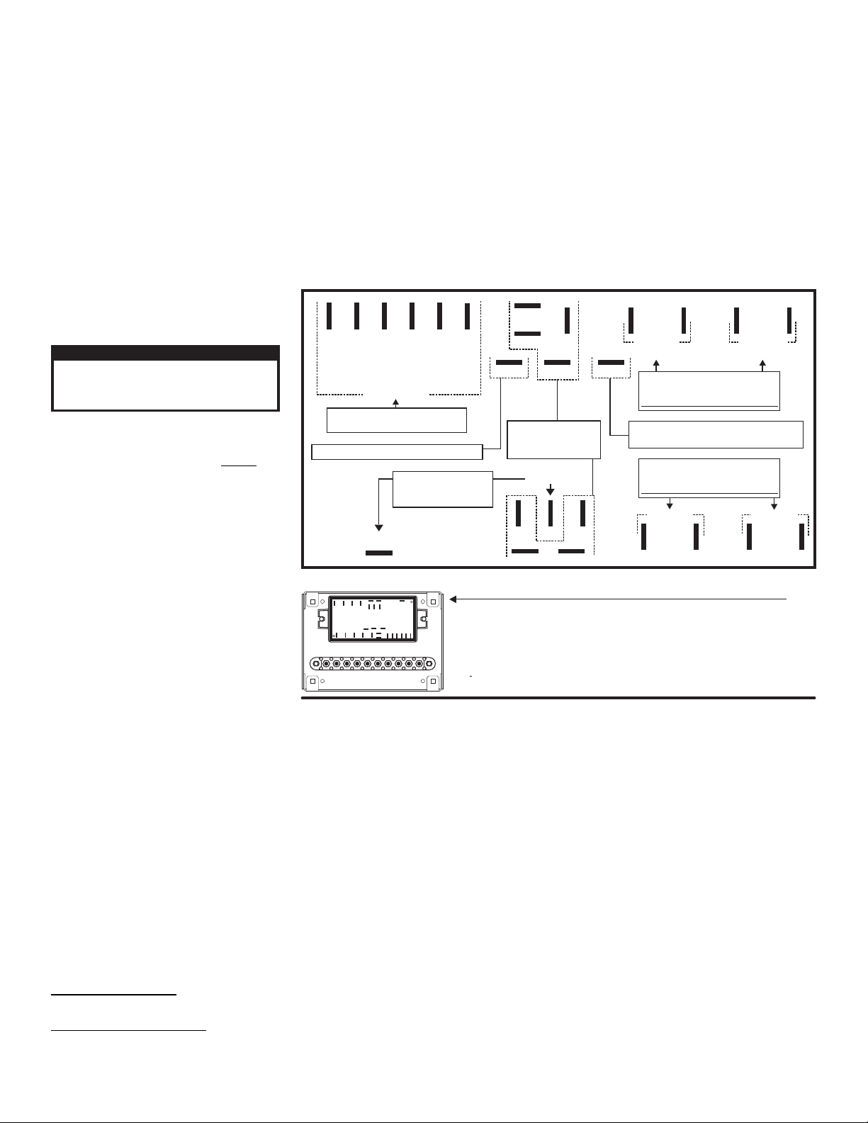
IMPORTANT WARNING!
Mounting the Flasher: One of the most common places chosen is against the rear wall of the cab. This is a good choice for several reasons, such
GND
GND
GND GND
GND
GND
GND
GND
Connect to the Negative Battery Terminal(-)
Plug Positive (+) wires from lighting
options into the output terminals.
MAXIMUM 5 AMPS PEAK EACH OUTPUT
Plug Negative (-) wires
from lighting options
into the GND terminals.
These terminals are to be
used for connecting the
optional Photocell.
(-) BAT
Photocell (+)
Photocell (-)
Scan-Lock
Low Power
Outputs
1&2
Outputs
3&4
Outputs
5&6
Outputs
7&8
Outputs
3&4
4
6
1
7
2
8
3
5
Outputs
7&8
Outputs
1&2
Outputs
5&6
Control Wires
(+) BAT
Connect to user supplied switches.
Fuse each control wire @ 1 AMP.
IMPORTANT: Outputs 1 thru 8 will handle a maximum of 5 AMPS Peak each.
IMPORTANT! Do NOT mount the Junction Box where it could be
exposed to moisture. The recommended mounting location
is within the passenger compartment.
Fig. 1 Flasher
WARNING: All Customer supplied wires that connect to the positive terminal of the battery
must be sized to supply at least 125% of the maximum operating current and fused "at the
battery" to carry that load. DO NOT USE CIRCUIT BREAKERS WITH THIS PRODUCT!
Plug Positive (+) wires from lighting
options into the output terminals.
Connect to the Positive (+) Battery Terminal
Fuse @ 25 AMPS.
MAXIMUM 5 AMPS PEAK EACH OUTPUT
as good air circulation and heat dissipation.
• The flasher is not waterproof. The mounting area must be dry and free from elements that could damage the unit (road salt, sand, snow).
• The flasher should not be exposed to excessive heat.
• The mounting area should be easily accessible for wiring and service purposes.
• Mounting the flasher to a metal surface is recommended for optimum heat dissipation.
• Be sure that the backside of the proposed mounting surface does not hide any wires, cables, fuel lines, etc., that could be damaged by
drilling the mounting holes.
• Select a location towards the middle of the cab.
• Be sure that the mounting location is a minimum of 8” from the cab floor.
• The flasher should be mounted on as flat a surface as possible.
DOT-LED®: Included are two, 10-12 gauge and
twenty four, 14-16 gauge Faston connectors to
connect your lighting options to the flasher and to
connect your power wires.
WARNING! All customer supplied wires that
connect to the positive terminal of the battery
must be sized to supply at least 125% of the
maximum operating current and FUSED
battery to carry that load. DO NOT USE CIRCUIT
BREAKERS WITH THIS PRODUCT!
IMPORTANT! Before returning the vehicle to
active service, visually confirm the proper
operation of this product, as well as all vehicle
components/equipment
Flasher Connection & Operation:
Connect your lighting options (Lightheads, beacons
etc...) to the flasher as shown. Connect the positive
wire of the lighting option to outputs 1 thru 8
(Each outlet will handle 5 AMPS PEAK). Connect
the negative wires of your lighting options to any of
the ground terminals. All terminals take a Faston
connector (supplied). Applying +12V DC to the
positive wire will activate its outlet or function (See
wiring diagram).
NOTE: Keep in mind that each control wire
activates two outlets each. Be sure to connect
lights that need to be on the same circuit accordingly, such as 2 front lightheads or both rear options would be. Fuse the control wires at 1 AMP each.
Hi/Low Power: This feature allows the user to step the unit down to low power operation for nighttime use
Option 1 / Latching Mode: By applying +12V DC to the "Hi/Low Power Control Wire” for less than 1 second, the system is latched into low power operation. The unit
must be turned off and then back on to restore normal high power (Momentary Switch).
Option 2 / Level Mode: Applying +12V DC to the "Hi/Low Power Control Wire” for more than 1 second holds the system in low power until the voltage is removed
(Toggle Switch).
Photocell (optional): If you have the photocell option, plug the BLACK wire into the negative photocell terminal, the RED wire into the positive photocell terminal and
the VIOLET wire into the low power terminal of the flasher (see wiring diagram). With the photocell hooked up, the system will switch to low power automatically at
night. Mount the photocell where it will be exposed to daylight, away from any vehicle lighting.
Scan-Lock™:
Scan-Lock allows the user to choose from several flash patterns. The entire system will display the pattern you choose (All outputs will display the same pattern).
TO CYCLE FORWARD THROUGH FLASH PATTERNS: Activate any of the outputs by applying power. With the outputs activated apply +VBAT to the Scan-Lock wire
for less than 1 second and release. Repeat to advance to next pattern.
TO CHOOSE A PATTERN: While cycling through the available flash patterns allowing a pattern to run for at least 5 seconds will configure it as the default pattern.
Now when activated the entire system will display this flash pattern.
TO RESET TO THE FACTORY DEFAULT PATTERN: Turn off all functions. Apply +VBAT to the Scan-lock wire while turning any of the functions back on. The system
is now restored to its factory default pattern.
Available Flash Patterns:
SignalAlert™ All outputs flash simultaneously > 4 - CometFlash® 75 Outputs 1, 2, 3 & 4 alternate with 5, 6, 7 & 8 > 5 - CometFlash® 75 Outputs 1, 3, 5 & 7 Alternate
with 2, 4, 6 & 8 > 6 - CometFlash® 75 All outputs flash simultaneously.
Available SSNF Flash Patterns:
with 3, 4, 5 & 6 > 8 - SSNF: Outputs 1, 4, 5 & 8 alternate with 2, 3, 6 & 7 > 9 - SSNF: All outputs flash simultaneously
1 - SignalAlert™ Outputs 1, 2, 3 & 4 alternate with 5, 6, 7 & 8 > 2 - SignalAlert™ Outputs 1, 3, 5 & 7 alternate with 2, 4, 6 & 8 > 3 -
at the
(Outputs 1, 2, 3 & 4 display CometFlash® and Outputs 5, 6, 7 & 8 display SingleFlash) 7 - SSNF: Outputs 1, 2, 7 & 8 alternate
Page 2
Page 3

REAR / 400 Series
FRONT OPTIONS:
FRONT LIGHTING OPTIONS FOR THE SYSTEMS
COVERED BY THIS MANUAL
A L L W I R E S C O N N E C T D I R E C T L Y
T O F L A S H E R .
BLK RED -
GROUND
POSITIVE
L31 Series Super-LED® Beacon
01-0684467-A6B
Micro Edge® 400 DOT Remote (3 Lt.)
01-06869641A2
01-0686929-1A1
01-06869641A0
01-0686929-1A2
GRN REAR: + POS. /GRN REAR: + POS. /
BLK: GND / FRNT & SIDEBLK: GND / FRNT & SIDE
RED: + POS. / FRNT & SIDERED: + POS. / FRNT & SIDE
WHT REAR: GND /WHT REAR: GND /
FRONTFRONT
RED:
BLK:
GRN:
WHT:
POSITIVE / FRONT
GROUND / FRONT
POSITIVE / REAR
GROUND / REAR
RED:
BLK:
GRN:
WHT:
POSITIVE / FRONT
GROUND / FRONT
POSITIVE / REAR
GROUND / REAR
Ultra Freedom Micro Edge®
01-0686900-A2
01-0686900-A3
FRONT FRONT
Micro 400 "3" Light DOT 01-06869291_1
BLK GND: / FRNT & SIDE
WHT GND REAR LEDs: /
GRN: + POS. / REAR LEDs
RED: + POS. / FRNT & SIDE
BLK GROUND: / FRNT & SIDE
WHT GND REAR LEDs: /
GRN: + POS. / REAR LEDs
RED: + POS. / FRNT & SIDE
FRONTFRONT
TO
VEHICLE
01-0686731-AXA / SQUARE
BRAKE-TAIL-TURN
400 SERIES
SPLIT
400 SERIES
SPLIT
400 SERIES
SPLIT
46-0764073-30
(
5/C
)
POS B
POS C
POS A
YEL GRN
WHITE
BROWN
-
-
-
/
46-076D170-02A (4/C)
TO
FLASHER
46-076D185-30 (2/C)
POS POS 21 - -RED BLK
POS 2 - RED
POS 4 - BLK
POS 5 - BLK
POS 6 - RED
POS 1 - RED
POS 3 - BLK
(+ POS.)
GROUND
YEL/GRN
WHITE
BROWN
BLU & WHT/BLK Not Used
(+ POSITIVE)
BRAKE/TURN
GROUND
(+ POS.) TAIL
6 POSITION SOCKET
CONNECTOR
WEDGE / 6 POS SOCKET
BUSSED CONNECTOR
With TIR3
400 SERIES
SPLIT
400 SERIES
SPLIT
400 SERIES
SPLIT
TO
FLASHER
TIR3
01-0686731-AOA
SQUARE
46-076D184-00 (6/C) 46-076D185-30 (2/C)
POS
POS 2
1 --RED
BLK
POS 1 - RED
POS 4 - BLK
(+ POS.)
GROUND
POS POS 21 - -RED BLK
8 POSITION SOCKET
CONNECTOR
WEDGE / 8 POS SOCKET
BUSSED CONNECTOR
POS 2 - RED
POS 3 - BLK
POS 5 - BLK
POS 6 - BLK
POS 7 - RED
POS 8 - RED
400 SERIES
BRAKE-TAIL-TURN
01-0686731-AXA
SQUARE
46-0764073-30
(
5/C
)
TO VEHICLE
400 SERIES
SPLIT
400 SERIES
SPLIT
400 SERIES
SPLIT
POS B
POS C
POS A
YEL GRN
WHITE
BROWN
-
-
-
/
With TIR3
TO
FLASHER
8 POSITION SOCKET
CONNECTOR
WEDGE / 8 POS SOCKET
BUSSED CONNECTOR
TIR3
46-076D184-00 (6/C) 46-076D185-30 (2/C)
POS
POS 2
1 --RED
BLK
POS 1 - RED
POS 4 - BLK
(+ POS.)
GROUND
POS POS 21 - -RED BLK
YEL/GRN
WHITE
BROWN
BLU & WHT/BLK Not Used
(+ POSITIVE)
BRAKE/TURN
GROUND
(+ POS.) TAIL
POS 2 - RED
POS 3 - BLK
POS 5 - BLK
POS 6 - BLK
POS 7 - RED
POS 8 - RED
46-0764073-30
(
5/C
)
TO
VEHICLE
400 SERIES
BACK-UP
400 SERIES
BACK-UP
400 SERIES
BACK-UP
400 SERIES
BRAKE-TAIL-TURN
01-0686731-AXVA / SQUARE
400 SERIES
SPLIT
400 SERIES
SPLIT
400 SERIES
SPLIT
POS B
POS C
POS A
YEL GRN
WHITE
BROWN
-
-
-
/
POS A
POS C
BLUE
WHT BLK
-
- /
With TIR3
8 POSITION SOCKET
CONNECTOR
WEDGE / 8 POS SOCKET
BUSSED CONNECTOR
TO
FLASHER
TIR3
46-076D184-00 (6/C) 46-076D185-30 (2/C)
POS
POS 2
1 --RED
BLK
BLU
WHT BLK
BACK-UP
GROUND/
(+ POS.)
YEL/GRN
WHITE
BROWN
(+ POS.)
BRAKE/TURN
GROUND
(+ POS.) TAIL
POS 2 - RED
POS 3 - BLK
POS 5 - BLK
POS 6 - BLK
POS 7 - RED
POS 8 - RED
POS 1 - RED
POS 4 - BLK
(+ POS.)
GROUND
01-0686731-AOA
SQUARE
46-076D170-02A (4/C)
400 SERIES
SPLIT
400 SERIES
SPLIT
400 SERIES
SPLIT
TO
FLASHER
46-076D185-30 (2/C)
POS 1 - RED
POS 3 - BLK
(+ POS.)
GROUND
POS POS 21 - -RED BLK
6 POSITION SOCKET
CONNECTOR
WEDGE / 6 POS SOCKET
BUSSED CONNECTOR
POS 2 - RED
POS 4 - BLK
POS 5 - BLK
POS 6 - RED
46-0764073-30
(
5/C
)
TO
VEHICLE
POS B
POS C
POS A
YEL GRN
WHITE
BROWN
-
-
-
/
POS A
POS C
BLUE
WHT BLK
-
- /
6 POSITION SOCKET
CONNECTOR
WEDGE / 6 POS SOCKET
BUSSED CONNECTOR
46-076D170-02A (4/C)
TO
FLASHER
46-076D185-30 (2/C)
POS 2 - RED
POS 4 - BLK
POS 5 - BLK
POS 6 - RED
POS 1 - RED
POS 3 - BLK
(+ POS.)
GROUND
BLU
WHT BLK
BACK-UP
GROUND/
(+ POS.)
YEL/GRN
WHITE
BROWN
(+ POS.)
BRAKE/TURN
GROUND
(+ POS.) TAIL
01-0686731-AXVA / SQUARE
BRAKE-TAIL-TURN
400 SERIES
BACK-UP
400 SERIES
BACK-UP
400 SERIES
BACK-UP
400 SERIES
SPLIT
400 SERIES
SPLIT
400 SERIES
SPLIT
POS POS 21 - -RED BLK
POS POS 21 - -RED BLK
Page 3
Page 4

REAR / 500 Series
TIR3
INSTALLATION
STRAIN
RELIEF
REAR / 700 Series
TO FLASHER
RED
B
LACK
(+ POSITIVE)
GROUND
500 SERIES
SPLIT
500 SERIES
SPLIT
500 SERIES
SPLIT
01-0683918-A0 / ANGLED
46-076D185-30
(
2/C
)
POS
POS 2
1 --RED
BLK
700 TIR LINEAR LED700 TIR LINEAR LED700 TIR LINEAR LED
01-0686737-A0 / SQUARE
TO FLASHER
RED
BLACK
(+ POSITIVE)
GROUND
46-076D185-30
(
2/C
)
POS
POS
1 2 -
RED
BLK
4 X 5/8 PLASTI
LOC SCREW
#4 FLAT
WASHER
TIR3 LIGHTHEAD
GROMMET
1/4 - 20 X 1 PFHMS
1/4 - 20 ELASTIC
STOP NUT
DOT TIR3
MOUNTING
PLATE
NUT
FLAT WASHER
CLIP
TO VEHICLE
BRAKE-TAIL-TURN
700 TIR LINEAR LED700 TIR LINEAR LED700 TIR LINEAR LED
01-0686737-AX / SQUARE
46-0764073-30
(
5/C
)
46-076D185-30
(
2/C
)
TO FLASHER
RED
BLACK
(+ POSITIVE)
GROUND
POS B
POS C
POS A
YEL GRN
WHITE
BROWN
-
-
-
/
POS POS 21 - -RED BLK
YEL/GRN
WHITE
BROWN
BLU & WHT/BLK Not Used
(+ POSITIVE)
BRAKE/TURN
GROUND
(+ POS.) TAIL
TO
FLASHER
46-076D185-30 (2/C)
With TIR3
700 TIR LINEAR LED700 TIR LINEAR LED700 TIR LINEAR LED
01-0686737-AO
SQUARE
TIR3
46-076D170-02A(4/C
)
POS 2 - RED
POS 4 - BLK
POS 5 - BLK
POS 6 - RED
6 POSITION SOCKET
CONNECTOR
WEDGE / 6 POS SOCKET
BUSSED CONNECTOR
POS 1 POS 2 -
RED
BLK
POS 1 - RED
POS 3 - BLK
(+ POS.)
GND
SOCKET
CONNECTOR
With TIR3
01-0686737AXV / SQUARE
TO VEHICLE
BRAKE-TAIL-TURN
700 TIR LINEAR LED700 TIR LINEAR LED
700 LED BACK-UP
700 LED BACK-UP700 LED BACK-UP
46-0764073-30
(
5/C
)
POS B
POS C
POS A
YEL GRN
WHITE
BROWN
-
-
-
/
POS
POS
BLUE
2 WHT BLK
1 -
- /
POS POS 21 - -RED BLK
6 POSITION SOCKET
CONNECTOR
WEDGE / 6 POS SOCKET
BUSSED CONNECTOR
TO
FLASHER
46-076D185-30 (2/C)
TIR3
46-076D170-02A(4/C
)
POS 2 - RED
POS 4 - BLK
POS 5 - BLK
POS 6 - RED
POS 1 - RED
POS 3 - BLK
(+ POS.)
GND
YEL/GRN
WHITE
BROWN
(
+12V BRAKE
)
(
GROUND
)
(
+12V TAIL
)
BLUE
WHT/BLK
(
+12V)BACK-UP
(
GROUND
)
500 SERIES
SPLIT
500 SERIES
SPLIT
500 SERIES
SPLIT
BRAKE-TAIL-TURN
01-0683918-AXU/ ANGLED
500 SERIES/ STEADY
TO VEHICLE
46-0764073-30
(
5/C
)
46-0764546-30(2/C
)
TO FLASHER RED
BLACK
(+ POSITIVE)
GROUND
POS B
POS C
POS A
YEL GRN
WHITE
BROWN
-
-
-
/
POS
POS
BLUE
2 WHT BLK
1 -
- /
POS POS 21 - -RED BLK
YEL/GRN
WHITE
BROWN
(
+12V BRAKE
)
(
GROUND
)
(
+12V TAIL
)
BLUE
WHT/BLK
(
+12V)BACK-UP
(
GROUND
)
TO FLASHER RED
BLACK
(+ POSITIVE)
GROUND
TO VEHICLE
46-0764073-30
(
5/C
)
POS B
POS C
POS A
YEL GRN
WHITE
BROWN
-
-
-
/
46-0764546-30(2/C
)
POS POS 21 - -RED BLK
YEL/GRN
WHITE
BROWN
BLU & WHT/BLK Not Used
(+ POSITIVE)
BRAKE/TURN
GROUND
(+ POS.) TAIL
500 SERIES
SPLIT
500 SERIES
SPLIT
500 SERIES
SPLIT
BRAKE-TAIL-TURN
01-0683918-AX / ANGLED
With TIR3
01-0686737-AX 700
SQUARE
46-0764073-30
(
5/C
)
POS B
POS C
POS A
YEL GRN
WHITE
BROWN
-
-
-
/
TO VEHICLE
YEL/GRN
WHITE
BROWN
BLU & WHT/BLK Not Used
(+ POSITIVE)
BRAKE/TURN
GROUND
(+ POS.) TAIL
6 POSITION SOCKET
CONNECTOR
WEDGE / 6 POS SOCKET
BUSSED CONNECTOR
TO
FLASHER
46-076D185-30 (2/C)
TIR3
46-076D170-02A(4/C
)
POS 2 - RED
POS 4 - BLK
POS 5 - BLK
POS 6 - RED
POS 1 - RED
POS 3 - BLK
(+ POS.)
GND
BRAKE-TAIL-TURN
700 TIR LINEAR LED700 TIR LINEAR LED
POS POS 21 - -RED BLK
DOT
HOUSING
DOT
HOUSING
CLIP
PIN CONNECTOR
MOUNTING
STUD
MOUNTING
STUD
MOUNTING
STUD
01-0686737-AXV / SQUARE
TO VEHICLE
46-0764073-30
(
5/C
)
46-076D185-30
(
2/C
)
TO FLASHER
RED
BLACK
(+ POSITIVE)
GROUND
POS B
POS C
POS A
YEL GRN
WHITE
BROWN
-
-
-
/
POS
POS
BLUE
2 WHT BLK
1 -
- /
POS
POS
1 2 -
RED
BLK
YEL/GRN
WHITE
BROWN
(
+12V BRAKE
)
(
GROUND
)
(
+12V TAIL
)
BLUE
WHT/BLK
(
+12V)BACK-UP
(
GROUND
)
BRAKE-TAIL-TURN
700 TIR LINEAR LED700 TIR LINEAR LED
700 LED BACK-UP700 LED BACK-UP
DOT
HOUSING
Page 4
Page 5

3.
RUN BACK ALONG
FRAME RAIL, INTO CAB
AND HOOK TO FLASHER
(SAME FOR OTHER SIDE)
1.
RUN WIRE FROM , DOWN FRONT AND ALONG
UNDERSIDE OF DUMP BODY TO HINGE POINT . . .
LIGHTS
2.
AT THE HINGE POINT,
LEAVE A12 INCH SERVICE LOOP
RUN WIRE FROM DOWN DUMP
BODY, ALONG FRAME RAILS, TO FLASHER.
REMOTE HEAD
(SAME INSTALLATION FOR OTHER SIDE)
DUMP HINGE POINT
Locking
Fixture
Locking
Cuff
Flex Tube
Ty-Wrap
Locking
Nut
Primary
Shaft
Housing
Plastic
Washer
Flex Tube Assembly:
1.
2.3.4.5.6.
7.
8.
9.
Insert the harness cables into the flex tube.
Be sure there is enough length of cable
pulled through the other end of the flex tube.
Fit the locking cuff onto the flex tube.
Slide the locking fixture onto the cables.
Slide the primary shaft housing onto the cables.
Position the locking fixture inside the primary
shaft housing.
Fit the flex tube completely around the end
of the primary shaft housing.
Tighten the locking cuff around the primary
shaft housing.
Insert the harness-flex tube assy. through
the wire opening in the remote head.
Secure the assembly with the locking
nut and install plastic washer and Ty-wrap
for strain relief then tighten securely.
White plastic
washer and
Ty-wraps for
strain relief
Housing
Cable
Cable
SIDE
VIEW
6 X 1-1/2"
PPHSMS
TRIPLE HOUSING
400 OPTIC
LENS
400 SERIES
LIGHTHEAD
MOUNTING FACE PLATE
400 SERIES
IMPORTANT! Rear housings should be mounted in a full upright, vertical position
BACK PLATE
MOUNTING FACEPLATE
#6 X 1/2" PPHSMS
700 SERIES LIGHTHEAD
700 SERIES
REAR HOUSING ASSEMBLY:
FLANGE
500 SERIES
LIGHTHEAD
GASKET
GROMMET
TRIPLE HOUSING
500 SERIES
#10 X 3/4"
PPHSMS
IMPORTANT: ALL CAPS
MUST BE INSTALLED IN
UNUSED HOLES.
Page 5
 Loading...