

Page 1

®
ENGINEERING COMPANY INC.
51 Winthrop Road
Chester, Connecticut 06412-0684
Phone: (860) 526-9504
Internet: www.whelen.com
Sales e-mail: [email protected]
Customer Service e-mail: [email protected]
Installation Guide:
Delta™ Independence™ Lightbar
(10/14 Function)
Whelen’s emergency vehicle warning devices must be properly mounted and wired in order to be effective and safe. Read and follow all of Whelen’s written
instructions when installing or using this device. Emergency vehicles are often operated under high speed stressful conditions which must be accounted for
when installing all emergency warning devices. Controls should be placed within convenient reach of the operator so that they can operate the system without
taking their eyes off the roadway. Emergency warning devices can require high electrical voltages and/or currents. Properly protect and use caution around
live electrical connections.Grounding or shorting of electrical connections can cause high current arcing, which can cause personal injury and/or vehicle
damage, including fire. Many electronic devices used in emergency vehicles can create or be affected by electromagnetic interference. Therefore, after
installation of any electronic device it is necessary to test all electronic equipment simultaneously to insure that they operate free of interference from other
components within the vehicle. Never power emergency warning equipment from the same circuit or share the same grounding circuit with radio
communication equipment. All devices should be mounted in accordance with the manufacturer’s instructions and securely fastened to vehicle elements of
sufficient strength to withstand the forces applied to the device. Driver and/or passenger air bags (SRS) will affect the way equipment should be mounted. This
device should be mounted by permanent installation and within the zones specified by the vehicle manufacturer, if any. Any device mounted in the deployment
area of an air bag will damage or reduce the effectiveness of the air bag and may damage or dislodge the device. Installer must be sure that this device, its
mounting hardware and electrical supply wiring does not interfere with the air bag or the SRS wiring or sensors. Mounting the unit inside the vehicle by a
method other than permanent installation is not recommended as unit may become dislodged during swerving; sudden braking or collision. Failure to follow
instructions can result in personal injury. Whelen assumes no liability for any loss resulting from the use of this warning device. PROPER INSTALLATION
COMBINED WITH OPERATOR TRAINING IN THE PROPER USE OF EMERGENCY WARNING DEVICES IS ESSENTIAL TO INSURE THE SAFETY OF
EMERGENCY PERSONNEL AND THE PUBLIC.
Warnings to Users
Warnings to Installers
Whelen’s emergency vehicle warning devices are intended to alert other operators and pedestrians to the presence and operation of emergency vehicles and
personnel. However, the use of this or any other Whelen emergency warning device does not guarantee that you will have the right-of-way or that other
drivers and pedestrians will properly heed an emergency warning signal. Never assume you have the right-of-way. It is your responsibility to proceed safely
before entering an intersection, driving against traffic, responding at a high rate of speed, or walking on or around traffic lanes. Emergency vehicle warning
devices should be tested on a daily basis to ensure that they operate properly. When in actual use, the operator must ensure that both visual and audible
warnings are not blocked by vehicle components (i.e.: open trunks or compartment doors), people, vehicles, or other obstructions. It is the user’s responsibility
to understand and obey all laws regarding emergency warning devices. The user should be familiar with all applicable laws and regulations prior to the use of
any emergency vehicle warning device. Whelen’s audible warning devices are designed to project sound in a forward direction away from the vehicle
occupants. However, because sustained periodic exposure to loud sounds can cause hearing loss, all audible warning devices should be installed and
operated in accordance with the standards established by the National Fire Protection Association.
Safety First
This document provides all the necessary information to allow your Whelen product to be properly and safely installed. Before beginning the installation and/or
operation of your new product, the installation technician and operator must read this manual completely. Important information is contained herein that could
prevent serious injury or damage.
WARNING: This product can expose you to chemicals including Methylene Chloride which is known to the State of California to cause cancer, and
Bisphenol A, which is known to the State of California to cause birth defects or other reproductive harm. For more information go to
www.P65Warnings.ca.gov.
• Proper installation of this product requires the installer to have a good understanding of automotive electronics, systems and procedures.
• Whelen Engineering requires the use of waterproof butt splices and/or connectors if that connector could be exposed to moisture.
• Any holes, either created or utilized by this product, should be made both air- and watertight using a sealant recommended by your vehicle
manufacturer.
• Failure to use specified installation parts and/or hardware will void the product warranty.
• If mounting this product requires drilling holes, the installer MUST be sure that no vehicle components or other vital parts could be damaged
by the drilling process. Check both sides of the mounting surface before drilling begins. Also de-burr the holes and remove any metal shards
or remnants. Install grommets into all wire passage holes.
• If this manual states that this product may be mounted with suction cups, magnets, tape or Velcro®, clean the mounting surface with a 50/50
mix of isopropyl alcohol and water and dry thoroughly.
• Do not install this product or route any wires in the deployment area of your air bag. Equipment mounted or located in the air bag deployment
area will damage or reduce the effectiveness of the air bag, or become a projectile that could cause serious personal injury or death. Refer to
your vehicle owner’s manual for the air bag deployment area. The User/Installer assumes full responsibility to determine proper mounting
location, based on providing ultimate safety to all passengers inside the vehicle.
• For this product to operate at optimum efficiency, a good electrical connection to chassis ground must be made. The recommended
procedure requires the product ground wire to be connected directly to the NEGATIVE (-) battery post (this does not include products that use
cigar power cords).
• If this product uses a remote device for activation or control, make sure that this device is located in an area that allows both the vehicle and
the device to be operated safely in any driving condition.
• Do not attempt to activate or control this device in a hazardous driving situation.
• This product contains either strobe light(s), halogen light(s), high-intensity LEDs or a combination of these lights. Do not stare directly into
these lights. Momentary blindness and/or eye damage could result.
• Use only soap and water to clean the outer lens. Use of other chemicals could result in premature lens cracking (crazing) and discoloration.
Lenses in this condition have significantly reduced effectiveness and should be replaced immediately. Inspect and operate this product
regularly to confirm its proper operation and mounting condition. Do not use a pressure washer to clean this product.
• It is recommended that these instructions be stored in a safe place and referred to when performing maintenance and/or reinstallation of this
product.
• FAILURE TO FOLLOW THESE SAFETY PRECAUTIONS AND INSTRUCTIONS COULD RESULT IN DAMAGE TO THE PRODUCT OR VEHICLE
Automotive: Lightbars
AND/OR SERIOUS INJURY TO YOU AND YOUR PASSENGERS!
©2004 Whelen Engineering Company Inc.
Form No.13913J (060810)
For warranty information regarding this product, visit www.whelen.com/warranty
Page 1
Page 2

Mounting
Pad
Adjustable
Mounting
Foot
Washer
Nut
Mounting
Plate
Standard
Mounting
Foot
Mounting
Pad
Washer
Nut
Mounting
Plate
BoltBolt
IMPORTANT! The lightbar should be located a minimum of 16" from any
NOTE: Unless otherwise specified, the lightbar mounting feet must be sitting as close to the edge of the roof as possible. They must also be
in full contact with the roof and not be hanging off the edge.
IMPORTANT: For strap mounting, be sure you have the right sized
lightbar for your vehicle. The bar should be approximately the same
width as the vehicle roof. If too large or small it will not mount properly
and may come loose during driving.
1/2" MIN. CLEARANCE
radio antennas!
Permanent Mounting:
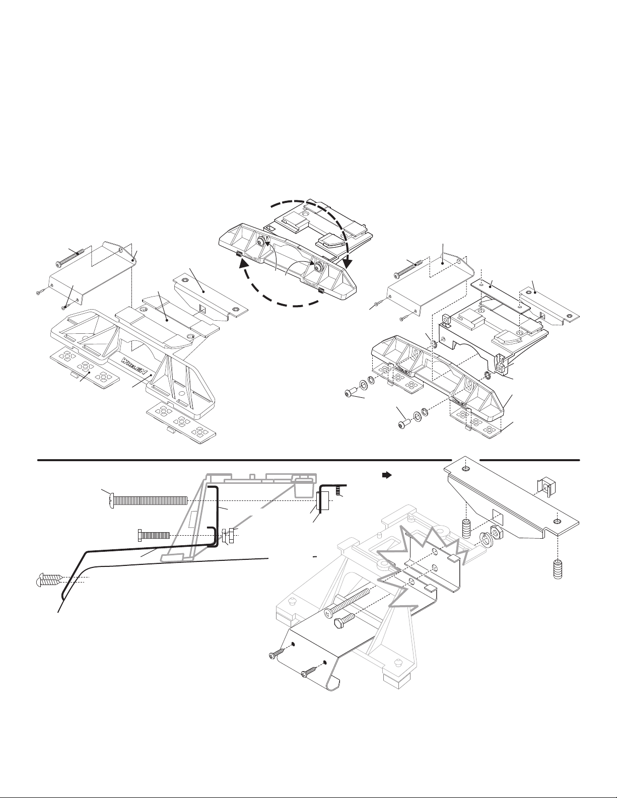
1. Locate the mounting foot and locking plate included with your lightbar. If not already
present, install the locking plate onto the mounting foot using the supplied set screws.
This plate should be centered from side to side on the mounting foot.
2. Flip lightbar upside-down to expose bottom of extrusion and place mounting foot onto extrusion.
3. Rotate the mounting foot 90° in a counter-clockwise direction. Make sure that the edges of the foot
swing into position under the extrusion mounting lip.
4. Repeat procedure for remaining foot and return lightbar to its right side-up position.
5. Position the lightbar onto the vehicle roof in the desired mounting location. One often
selected location is directly above the B-pillars. This area is the strongest part of the
roof. Refer to your lightbar manual for your lightbars cable exit location, to be sure
that the lightbar is facing the proper direction.
6. Adjust the two mounting feet outwards as close to the edge of the roof as possible.
Make sure that both mounting feet are in full contact with the roof (See below). There
should be no less than 1/2” clearance between the roof and the lightbar at their
closest point. When the mounting feet are in the proper position, lightly tighten the
allen head set screws.
7. Turn the lightbar upside down and firmly tighten all of the set screws from step 6
(2 or 4 per side).
8. Note that on the adjustable foot, use the hole in the pad as a guide to drill the two holes into
the mounting foot at the locations shown.
9. Place the lightbar in its final mounting position on the vehicle and mark the mounting hole locations off onto the
mounting surface. Remove lightbar and drill the mounting holes.
10. Place the lightbar back onto the vehicle lined up with the mounting holes and secure the mounting feet to the vehicle
using the supplied hardware.
Slide Bolt Mounting (Permanent):
1. Position the slide bolt mounting plates onto the bottom of the lightbar extrusion. These plates rotate into position the same way as the mounting foot. Position the plates as
far outward as possible (if a 3rd mounting plate is used, it should be positioned under the center of the lightbar).
2. Secure the plates to the extrusion using the set screws provided.
3. Position the lightbar onto the vehicle and mark the mounting bolt locations. Drill the necessary mounting holes using an appropriately sized drill bit sized for a 1/2” bolt.
Strap Mounting:
1. Locate the mounting foot, mounting plate and tinnerman plate included with
your lightbar. If not already present, install the mounting plate onto the
mounting foot. When properly positioned, this plate is centered from side-toside on the mounting foot.
2. Flip the lightbar upside-down to expose the bottom of the extrusion and place
the mounting foot onto the extrusion.
3. Rotate the mounting foot 90° in a counter-clockwise direction. Make sure that
the edges of the mounting foot swing into position under the extrusion
mounting lip. Install a tinnerman plate onto the extrusion in the same manner.
4. Repeat this procedure for the remaining mounting foot and tinnerman plate and
return the lightbar to its right side-up position.
5. Position the lightbar onto the vehicle roof in the desired mounting location. One
often selected location is directly above the B-pillars. This area is the strongest
part of the roof. Refer to your lightbar manual for cable exit location, to be sure
that the lightbar is facing the proper direction.
6. Adjust the two mounting feet outwards so that they are as close to the edge of
the roof as possible. Both mounting feet must be in full contact with the roof. Be
sure that there is no less than 1/2” clearance between the roof and the lightbar
at their closest point. When the mounting feet are in their proper position, lightly
tighten the mounting foot allen head set
screws.
7. Return the lightbar to an upside-down
position. Slide each tinnerman plate
outwards until it is fully engaged with its
corresponding mounting foot. With the
mounting feet and tinnerman plates in their
proper positions firmly tighten all of the set
screws (2 or 4 per side). Flip the lightbar
right side-up and return it to its mounting
position.
Page 2
Page 3
MOUNTING FOOT
TINNERMAN
NUT
FOOT
ANCHOR
PLATE
SET
SCREW
Plate slides into
lightbar extrusion
5" Mounting Foot
NUT
BOLT
SPLIT LOCK
WASHER
METAL SCREW
NOTE: The mounting straps are made to fit the contours of individual
vehicles. The strap
maylookdifferent.
shown here is for example only. The strap
for your vehicle
NOTE:
NOTE:
STRAP
SHEET
METAL
SCREWS
EXTENSION
VEHICLE ROOF
Tinnerman
Plate
Locking
Plate
Mounting
Plate
Mounting
Foot
Nut
Mounting
Pad
Adjustment
screws
Lock
Washer
Mounting
Foot
Mounting
Pad
Tinnerman
Plate
Mounting
Strap
Mounting
Screw
Tension
Bolt
Adjustable Mounting Foot / Model MKAJ
Standard Mounting Foot / Model MKEZ
Tighten screws
with torque wrench
set at 35 to 40 in/lbs
Mounting
Strap
Mounting
Screw
Tension
Bolt
8. When both mounting feet are in their proper position, lightly tighten the
allen head set screws.
9. Return the lightbar to an upside down position. Slide each anchor plate
outwards until it is fully engaged with its corresponding mounting foot.
With the mounting foot and anchor plate in their proper positions firmly
tighten all of the set screws (2 or 4 per side). Flip the lightbar right sideup and return it to its mounting position.
10.Open both drivers side doors. In the area directly below the mounting
foot, carefully pull the drivers side weather-strip away from the vehicle.
Remove enough so that the area where the mounting strap will be
secured to the vehicle is exposed. Repeat for passenger side.
11.Insert the mounting strap through the mounting foot. Be sure that the
strap fits flush against the area where it will be secured onto the vehicle.
Insert the tension bolt through the mounting strap and into the anchor
plate and secure it with the tinnerman nut. Tighten slightly with a long
shafted, Phillips screwdriver. Repeat procedure for passenger side.
12. If your mounting strap has mounting holes in the end, use these holes
as a template to drill holes through the strap and into the vehicle and
secure it with sheet metal screws. Repeat passenger side.
13.Firmly tighten the tension bolts to secure the lightbar to the vehicle.
NOTE: Model MKAJ is an adjustable mounting foot. On this model
you may loosen the screws on the rear of the foot and adjust the
angle of the lightbar. This feature can be used if the angle of the roof
is not level with the road.
IMPORTANT: To adjust the leveling screws you must use a torque
wrench set at 35 to 40 ft. lbs.
Installation: If your lightbar has a 5” mounting foot, it will
assemble differently than the standard mounting foot. It also
uses an extension to compensate for the extra height. Follow
these illustrations for assembly. Mounting to the lightbar is
the same.
Page 3
Page 4
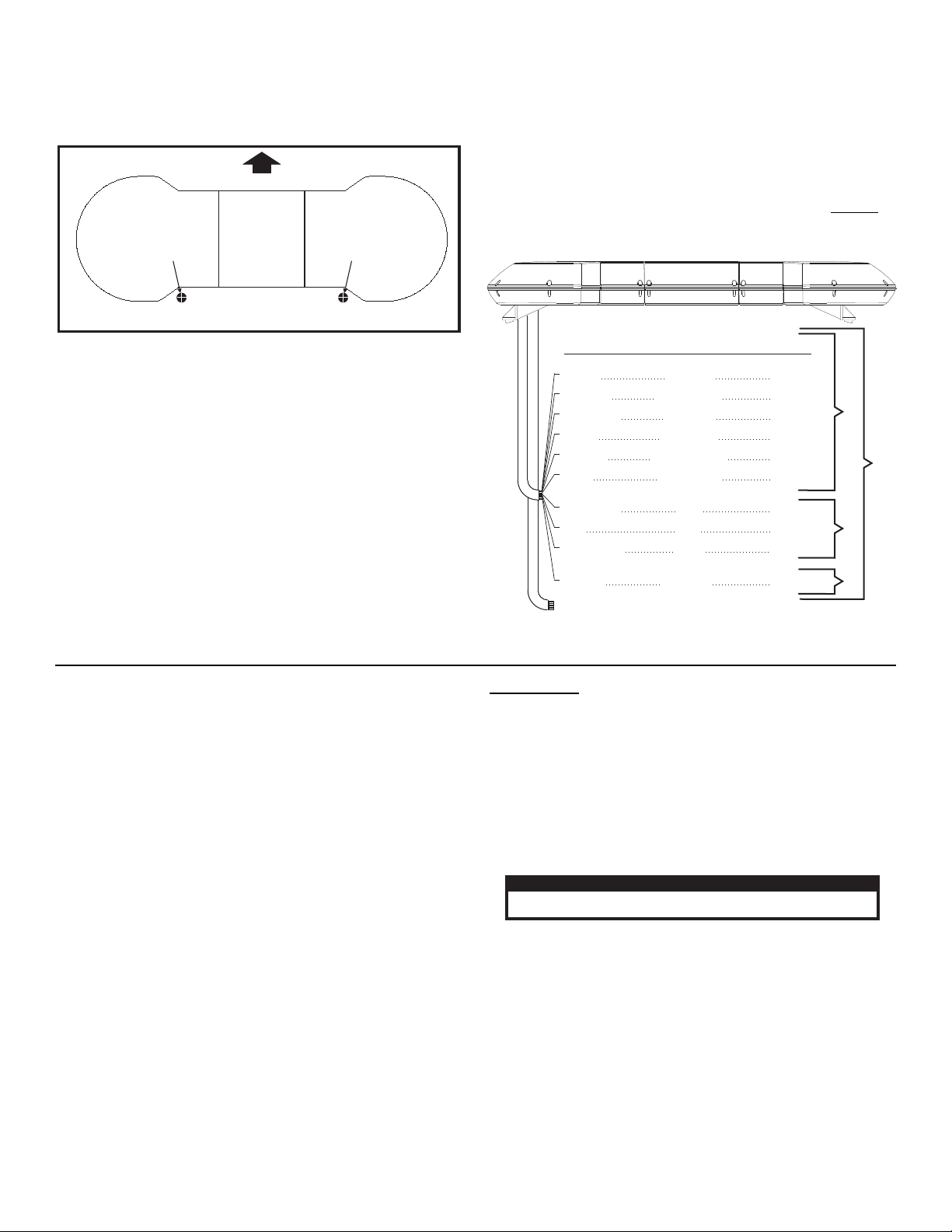
FRONT
For lightbars with
cables exiting the
Driver side of the
extrusion
Drill cable access hole in an area
appropriate for your lightbar
(see Warning).
For lightbars with
cables exiting the
Passenger side of
the extrusion
Routing the Cables:
Route cable to customer supplied switch box.
Oscillators
Front Flashers
Rear Flashers
Take-Down
GREEN
RED/WHITE
GRN/WHT
RED
RED/BLACK
WHT/VIO
WHITE/BLK
WHITE
YELLOW
BLUE
Inner
Outer
Center
Scan-Lock™
Drivers Alley
Passenger Alley
15 Amps
15 Amps
7.5 Amps
15 Amps
15 Amps
3 Amps
7.5 Amps
7.5 Amps
7.5 Amps
7.5 Amps
Color Fuse @
Lower Level
Upper Level
Misc.
NOTE: If dual, lower level MR-11 lightheads are used, their control
lines must be fused at 15 Amps.
To Chassis Ground
Function
Control Cable
CAUTION! DO NOT LOOK DIRECTLY AT THESE LED’S WHILE THEY ARE ON.
MOMENTARY BLINDNESS AND/OR EYE DAMAGE COULD RESULT!
IMPORTANT WARNING!
1. To protect the headliner from damage caused by drilling the cable
access hole through the vehicle roof, lower the headliner before
drilling to allow a 5” to 7” distance between roof and headliner.
WARNING! There is a roof support member that spans the
distance between the driver’s and passenger’s side. DO NOT
DRILL THROUGH THIS MEMBER! Adjust the location until
the hole can be drilled without contacting this support
member. Refer to “Safety First” on Page 1 for important
precautionary information.
2. Using a 1” hole saw, drill the cable access hole.
3. Use a round file to de-burr the edges of the cable access hole and
insert a 1” grommet (customer supplied) into the hole.
4. Insert the cables through the cable access hole into the vehicle. Use
RTV silicone to weatherproof the access hole after the cables are
pulled completely into the vehicle.
5. Route the cables one at a time to your power source. It is left to the
installation technician’s discretion where to run the cables, as
vehicles will vary.
Control Cable:
Route the cable towards a high-current switch panel such as the Whelen
model PCC10. Note: The use of switches with an insufficient current
rating will cause switch failure! Switches with a current rating of less
than 20 amps should not be used. For proper operation The ground
cable (BLACK) must be connected to the vehicle’s chassis ground.
WARNING! All customer supplied wires that connect to the
positive terminal of the battery must be sized to supply at
least 125% of the maximum operating current and FUSED
the battery to carry that load. DO NOT USE CIRCUIT
BREAKERS WITH THIS PRODUCT!
at
Scan-Lock™ (white-violet)
With the desired lighthead activated:
TO CHANGE PATTERNS: To cycle forward to the next available pattern
apply +12 volts to the WHITE-VIOLET wire for less than 1 second and
release. To cycle back to the previous pattern apply +12 volts to the
WHITE-VIOLET wire for more than 1 second and release.
TO CHANGE THE DEFAULT PATTERN: When the desired pattern is
displayed, allow it to run for more than 5 seconds. The lighthead will now
display this pattern when initially activated.
Flash Patterns:
1. SignalAlert™ 1 Alternates with 2
2. SignalAlert™ 1 & 2 Simultaneous
3. SignalAlert™ 3 Cycles of 1A & 3
Cycles of 1B
4. CometFlash® 1 Alternates with 2
5. CometFlash® 1 & 2 Simultaneous
6. CometFlash® 3 Cycles of 2A & 3
Cycles of 2B
7. DoubleFlash 1 Alternates with 2
8. DoubleFlash 1 & 2 Simultaneous
9. DoubleFlash 3 Cycles of 3A and 3
Cycles of 3B
10. SingleFlash 1 Alternates with 2
11. SingleFlash 1 & 2 Simultaneous
12. SingleFlash 3 Cycles of 4A and 4
Cycles of 4B
13. SteadyFlash 1 & 2 Steady / 3 & 4
Single Flash
14. Steady 1, 2, 3 & 4 Steady
TO RESTORE THE FACTORY DEFAULT PATTERN: Turn power to the
lighthead off. While applying +12 volts to the WHITE-VIOLET wire, turn
power to the lighthead on. The factory default pattern is now displayed.
Use a Normally Open Momentary Switch for Scan-Lock™ operation.
IMPORTANT! Before returning this vehicle to active service, visually confirm the proper operation of this product, as well as all vehicle
components/equipment.
CONTROL CABLE: A control cable with all available options for the
DELTA™ is shown for reference. Not all options are available in all
lightbars. For the wire I.D. of your lightbar, refer to the list included
with the lightbar. You will have either a 10 or 17 conductor cable.
VIOLET . . . . . . . . . . . . Optional Flashers . . . . . . . . . . . Fuse @ 7.5 amps
WHITE/YELLOW. . . . . Optional Flashers . . . . . . . . . . .Fuse @ 7.5 amps
BLACK/WHITE . . . . . . Optional Flashers . . . . . . . . . . .Fuse @ 7.5 amps
BLUE/ORANGE . . . . . Optional Flashers . . . . . . . . . . .Fuse @ 7.5 amps
BLUE/BLACK . . . . . . . Optional Flashers . . . . . . . . . . .Fuse @ 7.5 amps
BLUE/WHITE . . . . . . . Optional Flashers . . . . . . . . . . . Fuse @ 7.5 amps
GREEN/BLACK . . . . . Optional Flashers . . . . . . . . . . . Fuse @ 7.5 amps
WHITE/VIOLET . . . . . . Scan-Lock™ . . . . . . . . . . . . . . . . . Fuse @ 1 amp
WHITE/BLACK . . . . . . Take-Downs . . . . . . . . . . . . . . .Fuse @ 7.5 amps
GREEN/WHITE . . . . . . Optional Flashers . . . . . . . . . . .Fuse @ 7.5 amps
WHITE . . . . . . . . . . . . . Drivers Side Alley . . . . . . . . . . .Fuse @ 7.5 amps
YELLOW . . . . . . . . . . . Passengers Side Alley. . . . . . . . Fuse @ 7.5 amps
BLUE. . . . . . . . . . . . . . Optional Flashers . . . . . . . . . . .Fuse @ 7.5 amps
RED . . . . . . . . . . . . . . . Inner Rotators . . . . . . . . . . . . . . Fuse @ 15 amps
RED/WHITE . . . . . . . . Outer Rotators . . . . . . . . . . . . . . Fuse @ 15 amps
RED/BLACK . . . . . . . . Center Rotators . . . . . . . . . . . . . Fuse @ 15 amps
GREEN . . . . . . . . . . . . Oscillating Rotators . . . . . . . . . . Fuse @ 15 amps
NOTE: For 400 Series LED flashers, LR11 Alley lights or LR11 takedowns, use a 3 amp fuse.
Page 4
Page 5
02-0363716-00
ROTATING REFLECTOR 150-12-H1
12
DELTA STD. ROT CTR/ATOR/.
DELTA 2 STD INBD/ ROTATOR .
02-0484131-02
02-0484131-00
SCREW GROMMET #6 #8 FASTEX/
SCREW 8 x 3/8 PPHSMS / 410 SS/
RIVET POP AVEX 1691-0512/
13-062C40-16J
02-0363716-02
17-0510040-30
15-081416-060
4
4
2
2
2
4
4
1
2
2
8
4
2 121
02-0484131-04
02-0484131-35
DELTA STD C R MIRROR/ ROT. / T / with
02-0484131-05
02-0484131102
DELTA HI with MIRRORS DUAL C RROT. T
02-0484131-01
02-0484131-03
DELTA HI C R/ ROTATOR / T
DELTA 2 HI INBOARD/ ROTATOR
ROTATING REFLECTOR 175-12-H1
4
2
68-5443033-00
MIRROR / CTR. MNT. ROT. / DELTA
DELTA 2 STD MIRROR DUAL C R/ ROT. / / T
4
4
8
4
2
4
2
2
4
4
2
2
DELTA 2 HI with MIRRORS DUAL C RROT. T
2
3
ITEM PART NUMBER DESCRIPTION
QTY QTY QTY QTY
4
5
6
1
QTYQTYQTYQTY
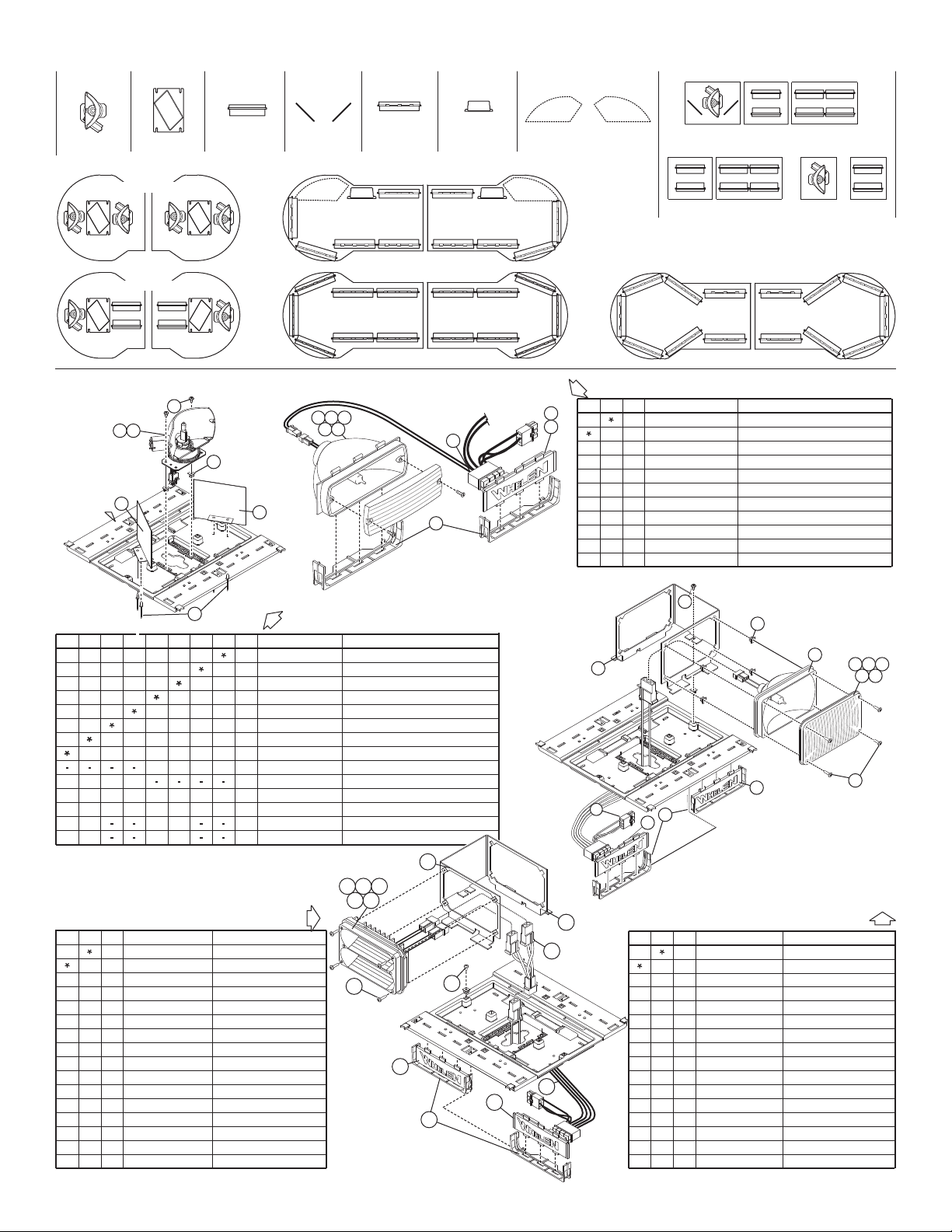
UPPER LEVEL: ROTATOR OPTIONS
Options:
options shown are available for the Delta™ lightbar, assembly and parts.
2 1
3
FOR
REFERENCE
6
6
5
4
01-06835772G3
01-0269831-01
02-0484131-__
02-0484131-__
01-06835772C3
01-06835772B3
01-06835772A3
02-0364086-00
09-1363542-00
46-0784112-02
DELTA ADD 1 500 HALOGEN FLASHER
DELTA ADD 2 500 HALOGEN FLASHERS
500 HALOGEN/2 WIRE /2 POS AMP/AMB
RETAINER LIGHTHEAD MTG / DELTA
HARNESS FLASHER / DELTA SERIES
ELEC 2 CH FLASHER DELTA
FILLER PANEL 500 SERIES/
01-06835772R3
500 HALOGEN WIRE /2 POS AMP/BLU/
500 HALOGEN 2 WIRE /2 POS AMP/CLR/
500 HALOGEN 2 WIRE /2 POS AMP/GRN/
500 HALOGEN 2 WIRE/ 2 POS AMP/RED/
2
3
111
1
ITEM
PART NUMBER
PART DESCRIPTION
QTY QTY
4
5
6
7
8
9
A/R
A/R
A/R
A/R
A/R
A/R
A/R
A/R
A/R
A/R
34
111
LOWER LEVEL: 500 SERIES HALOGEN FLASHER
51637
849
2
ROTATOR
ASSEMBLY
UPPER LEVEL
MIRROR:
DIAMOND
UPPER LEVEL
CORNER
400 SERIES
LIGHTHEAD
UPPER LEVEL
MIRROR:
FLAT
UPPER LEVEL
DUAL CENTER
500 SERIES
LIGHTHEAD
LOWER LEVEL
OSCILLATOR ASSEMBLIES
TIR3
LIGHTHEAD
LOWER LEVEL
CORNER
CORNER CONFIGURATION
CORNER CONFIGURATION
OSC OSC
CORNER CONFIGURATION
OSC OSC
LOWER LEVEL
CORNER
LOWER LEVEL CONFIGURATIONS
DUAL
CENTER
SINGLE
CENTER
SINGLE / CENTER
DUAL / CENTER
Available Configurations:
UPPER LEVEL
CONFIGURATION
CORNER
CONFIGURATION
UPPER LEVEL: HALOGEN FLASHER
8
4
121
1
ELEC 2 CH FLASHER DELTA
2 - 400 HALOGEN FLASHERS
1 - 400 HALOGEN FLASHER
02-0484131-__
02-0484131-__
FILLER PANEL 500 SERIES/
SCREW 8 x 1/2" PPHSMS / 410 SS/
MTG. BRCKT 400 SERIES
LENS AMB 400 OPTIC / SEAL/
HARNESS FLASHER / DELTA
SCREW 6 x 1 1/2" PPHSMS/
RETAINER LIGHTHEAD MTG
REFLECT. 400 SERIES HALO.
02-0363189-00
02-0364086-00
09-1363542-00
07-263737-000
01-0269831-01
15-061416-240
68-1183726-1S
15-081416-080
46-0784112-02
13-062C40-16J
GROMMET #6 #8 FASTEX
1
10
2
2
2
11
1
1
2
1
5
68-1183726-2S
LENS BLU 400 OPTIC / SEAL/
68-1183726-3S
LENS CLR 400 OPTIC / SEAL/
68-1183726-5S
68-1183726-4S
LENS GRN 400 OPTIC / SEAL/
LENS / RED 400 OPTIC / SEAL
2
3
ITEM PART NUMBER DESCRIPTION
QTY QTY
11
12
13
14
4
5
6
7
8
9
10
1
A/RA/R
A/RA/R
A/RA/R
A/RA/R
A/RA/R
1
5
4
7
2
8
6
10 11 12
13 14
3
9
5
7
4
9
101311
1
14
6
3
2
12
8
DELTA ADD 400 SERIES LED FLASHER
ITEM
PART NUMBER
DESCRIPTION
02-0484131-__
02-0484131-__
02-0364086-00
09-1363542-00
07-263737-000
01-0269831-01
013-062C40-16J
ELEC 2 CH FLASHER DELTA
2 400 LINEAR FLASHER-S
1 - 400 LINEAR FLASHER
FILLER PANEL 500 SERIES/
MTG. KT. /BR 400 SERIES
RETAINER LIGHTHEAD MTG
SCREW GRMT #6 #8 FASTX./
46-0784112-02
15-061416-240
01-0286361233
01-0286361255
01-0286361244
01-0286361211
15-081416-080
46-0784112-04
01-0286361222
10
2
2
1
1
8
2
2
A/R
A/R
A/R
A/R
A/R
1
QTY
2
1
1
1
5
1
4
1
1
A/R
A/R
A/R
A/R
A/R
400 LIN LED SPLIT / RED-RED
400 LIN LED SPLIT / GRN GRN-
400 LIN LED SPLIT / CLR CLR-
400 LIN LED SPLIT / BLU BLU-
HARNESS FLASHER / DELTA
SCREW 6 x 1-1/2" PPHSMS/
8 x 1/2" PPHSMS / 410 SS
400 LED SPLIT / AMB AMBLIN -
HARNESS UPPER LED ADAPT.
2
3
11
12
13
14
4
5
6
7
8
9
10
1
QTY
Page 5
Page 6
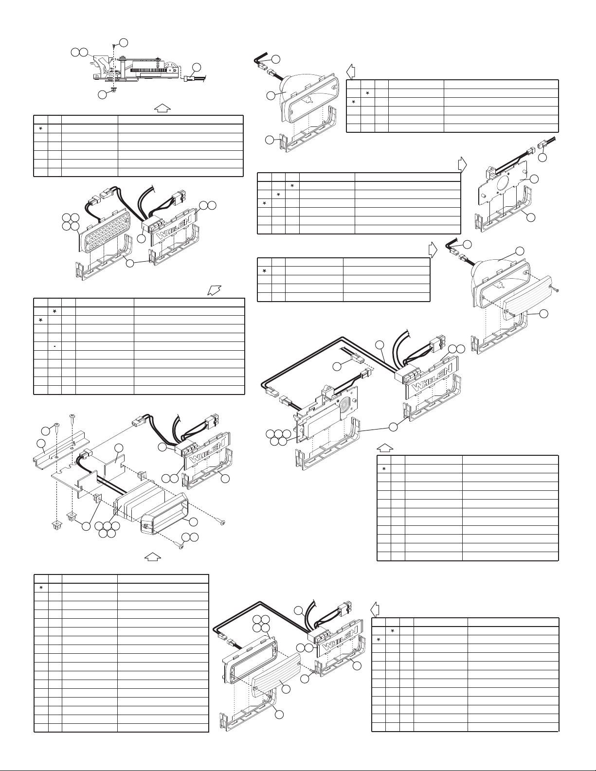
LOWER LEVEL: OSCILLATORS
1
1
4
1
4
ASS'Y OSCILLATOR DRIVER/
SCREW 8 x 3/8" PPHSMS / 410 SS/
SCREW GROMMET #6 #8 FASTEX/
DELTA ADD 2 OSCILLATORS/
13-062C40-16J
15-081416-060
02-0384055-00
02-0484131-09
ASS'Y / HARNESS TAKEDOWN LIGHT / DELTA
46-0784112-00
02-0384055-01
ASS'Y OSCILLATOR PASSENGER/
2
3
ITEM
PART NUMBER
DESCRIPTION
QTY
4
5
1
5 6
7 8
4
1 3
2
LOWER LEVEL: 500 SERIES 5MM FLASHERS
01-0269831-01
46-0784112-02
02-0484131-__
09-1363542-00
02-0364086-00
2
1
1
ASS'Y ELEC 2 CH FLASHER DELTA/
ASS'Y HARNESS FLASHER / DELTA SERIES/
ASS'Y RETAINER LIGHTHEAD MTG / DELTA/
FILLER PANEL 500 SERIES/
1
4
1
1
02-0383558A12
SUB ASSY 500 LED STEADY AMB 2 POS. AMP//
02-0484131-__
OPT DELTA ADD 2 500 5MM LED FLASHERS
02-0383558A22
02-0383558AC2
02-0383558A52
OPT DELTA ADD 1 500 5MM LED FLASHER
SUB ASSY 500 LED STEADY BLU 2 POS. AMP//
SUB ASSY 500 LED STEADY RED 2 POS. AMP//
SUB ASSY 500 LED STEADY CLR 2 POS. AMP//
2
3
ITEM
PART NUMBER
DESCRIPTION
QTY QTY
4
5
6
7
8
1
A/R
A/R
A/R
A/R
A/R
A/R
A/R
A/R
2
4
1 3
2
10
9
576
8
7
3
8
4
6
R
11
2
1 5
91210
13
14
15 16
3
2
1
DELTA ADD 1 MR11 TAKE DOWN LIGHT
DELTA ADD 2 MR11 TAKE DOWN LIGHTS
ASSY RETAINER LIGHTHEAD MTG / DELTA/
SUB ASSY SINGLE MR11 / DELTA SERIES/
ASSY / HARNESS TAKE DOWN LIGHT / DELTA
02-0484131-80
02-0363847-00
46-0784112-00
02-0484131-81
02-0364086-00
2
3
11
ITEM
PART NUMBER
DESCRIPTION
QTY QTY
12
112
LOWER LEVEL TAKE DOWN: MR11 ALLEY LIGHTS or
DELTA ADD 2 MR11 ALLEY LIGHTS
02-0484131-82
21
4
3
5
DELTA™ LIGHTBAR / Available Options
(
continued
)
1 3
4
5
2
678
910
LOWER LEVEL: 500 SERIES TAKE DOWN
DELTA ADD 1 HALOGEN TAKE DOWN LIGHT
DELTA ADD 2 HALOGEN TAKE DOWN LIGHTS
SUB ASSY 500 HALO REFL / LAMP 2 POS AMP//
ASSY / RETAINER LIGHTHEAD MTG / DELTA
02-0484131-07
02-0383577-23
46-0784112-00
02-0484131-06
02-0364086-00
ASSY / HARNESS TAKEDOWN LIGHT / DELTA
2
3
ITEM
PART NUMBER
DESCRIPTION
QTY QTY
1
11
12
12
1
2
3
LOWER LEVEL: 500 SERIES TIR6 LED FLASHER
68-1963583-30
01-026B670252
01-026B670232
01-026B670222
01-026B670212
02-0364086-00
02-0484131-__
02-0484131-__
01-0269831-01
46-0784112-02
09-1363542-00
RETAINER LT. HEAD MTG / DELTA
ADD 2 500 TIR6 LED FLASHERS
ADD 1 500 TIR6 LED FLASHER
ELEC 2 CH FLASHER DELTA
LENS CLR OPTIC LED 20° 500 SERIES/
S ASY 500 TIR LTBR MT / STDY AMB./
HARNESS FLASHER / DELTA SERIES
FILLER PANEL 500 SERIES/
15-065419-080
SCREW/6x1/2PPHPLASTI / SS
S. ASY / 500 TIR LTBR MT / STDY BLU
S. ASY / 500 TIR LTBR MT / STDY CLR
S. ASY / 500 TIR LTBR MT / STDY RED
2
3
ITEM
PART NUMBER
DESCRIPTION
QTY QTY
4
5
6
7
8
9
10
1
111
1
A/R
A/R
A/R
A/R
1
24
A/R
A/R
A/R
A/R
2
34
11
LOWER LEVEL: 500 SERIES ALLEY LIGHTS
DELTA ADD 2 HALOGEN ALLEY LT.'S
500 HALO. / 2 WIRE / 2 POS AMP CLR
HARNESS ALLEY LIGHT / DELTA
02-0484131-08
01-06835772C3
46-0784112-01
02-0364086-00
RETAINER LT. HEAD MTG / DELTA
2
3
1
ITEM
PART NUMBER
DESCRIPTION
QTY
2
12
LOWER LEVEL
(
For use with Delta Oscillators only
)
: 2 TIR 3 LEDS
02-0364086-00
11-763742-001
02-0484131-__
01-0269831-01
09-1363542-00
07-243041-000
1
2
2
1
2
RETAINER LT. HEAD MOUNTING DELTA
FLANGE SURFACE MT TIR3 LTHD/./.
DELTA: 2 TIR3 LED LOWER LEVEL
BRACKET MOUNTING TIR3 / DELTA/
FILLER PANEL 500 SERIES/
ELEC 2 CH FLASHER / FILLER PANEL
4
4
13-062C40-16J
15-061416-120
SCREW GROMET #6 #8 FASTEX/
SCREW 6 x 3/4" PPHSMS / 410 SS/
2
07-243110-000
BRACKET MOUNTING PDM/
SCREW 8 x 1/2" PPHSMS / 410 SS/
4
A/R
1
HARNESS FLASHER / DELTA SERIES
15-081416-080
46-0784112-02
02-0363752212
TIR3 LED LTHD STEADY AMB AMP//
SCREW 8 x 3/8" PPHSMS / 410 SS/
15-081416-060
-4
02-0363752222
02-0363752232
02-0363752242
02-0363752252
TIR3 LED LTHD STEADY BLU AMP//
TIR3 LED LTHD STEADY CLR AMP//
TIR3 LED LTHD STEADY GRN AMP//
TIR3 LED LTHD STEADY RED AMP//
2
3
ITEM
PART NUMBER
DESCRIPTION
QTY
11
12
13
14
15
16
4
5
6
7
8
9
10
1
A/R
A/R
A/R
A/R
LOWER LEVEL: MR11 ALLEY & TIR3 LED
RETAINER LIGHTHEAD MTG / DELTA
02-0364086-00
ELEC 2 CH FLASHER DELTA
DELTA: ADD 1 500 HALOGEN FLASHER
02-0484131-__
01-0269831-01
SUB ASY MR11/AMB TIR3 LED / DELTA/
HARNESS FLASHER / DELTA SERIES
HARNESS ALLEY LIGHT / DELTA SERIES
FILLER PANEL 500 SERIES/
46-0784112-02
09-1363542-00
46-0784112-01
02-0363859-10
02-0363859-20
SUB ASY MR11/BLU TIR3 LED / DELTA/
02-0363859-30
SUB ASY MR11/CLR TIR3 LED / DELTA/
02-0363859-40
SUB ASY MR11/GRN TIR3 LED / DELTA/
02-0363859-50
SUB ASY / MR11 RED TIR3 LED / DELTA/
2
3
ITEM
PART NUMBER
DESCRIPTION
QTY
4
5
6
7
8
9
10
1
1
1
1
A/R
A/R
A/R
A/R
A/R
4
1
2
1
3
Page 6
Page 7
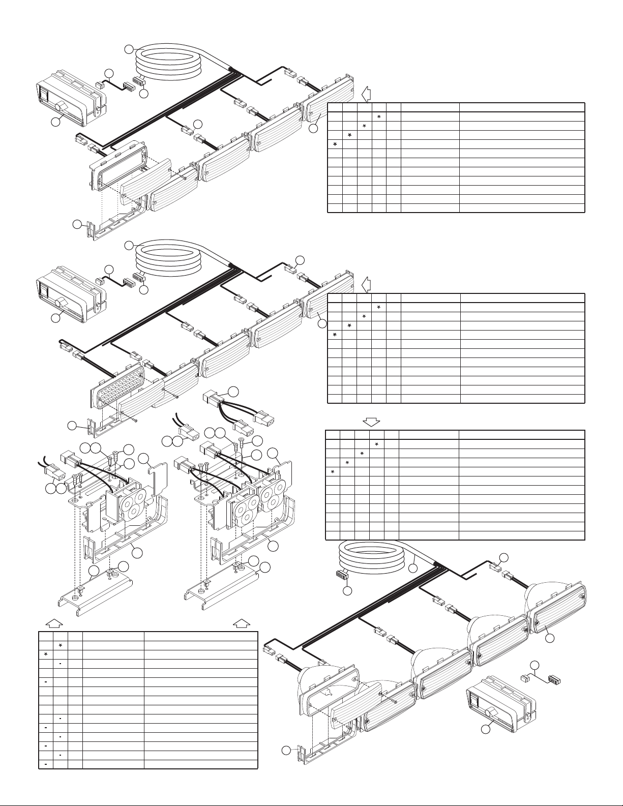
6
NOTE: 5 LIGHT TA SHOWN
5
2
4
3
LOWER LEVEL: 5MM LED TRAFFIC ADVISOR
LOWER LEVEL: TRAFFIC ADVISORTIR6 LED
3
4
2
1
7
6
5
1
7
6
5
4
3
2
46-0743070-00
39-0416313-04
02-0364086-00
01-0663530-AA
01-0682340-00
39-0402023-04
02-0484131-25
02-0484131-24
02-0484131-22
02-0484131-23
46-0763757-01
DELTA OPT 5 LIGHT TIR6 LED TRAFFIC ADVISOR/
DELTA OPT 8 LIGHT TIR6 LED TRAFFIC ADVISOR/
DELTA OPT 7 LIGHT TIR6 LED TRAFFIC ADVISOR/
DELTA OPT 6 LIGHT TIR6 LED TRAFFIC ADVISOR/
ASSY CABLE 16/C 20 GA. 20' / DELTA SERIES/
HOUSING 2 POS SOCKET / COMM MATE N LOK/
ASSY RETAINER LIGHTHEAD MTG / DELTA/
ASSY 500 SERIES TIR LED AMBER / AMBER/
HOUSING 16 POS PIN MOTOT MT/
ASSY ACTRL1A CONTROL HEAD/T
ASSY / CABLE ADAPTER CNTRL HD / SWITCH GND
2
3
ITEM PART NUMBER DESCRIPTION
QTY QTY QTY QTY
4
5
6
7
1
2121122
1
A/R
A/R
A/RA/R
A/R
A/R A/R
A/R
A/R
A/R
A/R
A/R
2222
2222
02-0484131-21
02-0484131-20
02-0484131-19
02-0484131-18
46-0763757-01
46-0743070-00
39-0416313-04
39-0402023-04
02-0364086-00
02-0383558AA2
01-0683850-00
DELTA OPT 8 LIGHT 5MM LED TRAFFIC ADVISOR/
DELTA OPT 7 LIGHT 5MM LED TRAFFIC ADVISOR/
DELTA OPT 6 LIGHT 5MM LED TRAFFIC ADVISOR/
DELTA OPT 5 LIGHT 5MM LED TRAFFIC ADVISOR/
ASSY / CABLE ADAPTER CNTRL HD / SWITCH GND
ASSY CABLE 16/C 20 GA. 20' / DELTA SERIES/
HOUSING 16 POS PIN MOTOT MT/
HOUSING 2 POS SOCKET / COMM MATE N LOK/
ASSY RETAINER LIGHTHEAD MTG / DELTA/
SUB ASSY 500 LED STEADY MAX AMB/AMB//
ASSY TRAFFIC ADV C L HEAD LED TACTLD1/TR/
2
3
ITEM PART NUMBER DESCRIPTION
QTY QTY QTY QTY
4
5
6
7
5678
11111
5
678
5
678
1111
1111
1111
LOWER LEVEL: TRAFFIC ADVISOR: ADD HALOGEN
HOUSING 2 POS SOCKET / COMM MATE N LOK/
HOUSING 16 POS PIN MOTOT MT/
ASSY CABLE 16/C 20 GA. 20' / DELTA SERIES/
ASSY / CABLE ADAPTER CNTRL HD / SWITCH GND
DELTA OPT 5 LIGHT HALOGEN TRAFFIC ADVISOR/
ASSY 500 HALOGEN 2 WIRE 2 POS AMP/AMBER///
ASSY RETAINER LIGHTHEAD MTG / DELTA/
ASSY TACTRL1A CONTROL HEAD/
39-0402023-04
39-0416313-04
46-0743070-00
46-0763757-01
02-0484131-14
01-0682340-00
01-06835772A4
02-0364086-00
02-0484131-15
02-0484131-16
02-0484131-17
DELTA OPT 6 LIGHT HALOGEN TRAFFIC ADVISOR/
DELTA OPT 7 LIGHT HALOGEN TRAFFIC ADVISOR/
DELTA OPT 8 LIGHT HALOGEN TRAFFIC ADVISOR/
2
3
ITEM PART NUMBER DESCRIPTION
QTY QTY
4
5
6
7
1
1
1
1
1
1
5
6
111
QTY QTY
1
1
1
1
1
1
7
8
11
5
678
5
678
DELTA™ LIGHTBAR / Available Options
(
continued
)
1
7
MTG BRACKET PDM with LR11
SCREW 6 x 1/2 PPH PLASTI / SS/
SCREW 6-32 X 1/4 PPHMS SEMS IT LOCK/ with
"Y" HARNESS INTERIOR BAR
SUB ASY SINGLE LR11 DELTA LOWER LEVEL/
SUB ASY DUAL LR11 DELTA LOWER LEVEL/
HARNESS TAKEDOWN LIGHT / DELTA
HARNESS ALLEY LIGHT / DELTA
ASS'Y RETAINER LIGHTHEAD MTG / DELTA/
SCREW 8-32 X 3/4 PPHMS SS/
DELTA ADD 2 LR11 TAKE DOWN LIGHTS
DELTA ADD 2 LR11 ALLEY LIGHTS
BRACKET MTG LR11 ALLEY DELTA/
SCREW GROMMET #6 #8 FASTEX/
02-0484131___
02-0484131___
07-243733-000
15-065419-080
14-062216-041
46-0743226-00
01-026B085-__
01-026B085-__
46-0784112-00
46-0784112-01
02-0364086-00
14-082216-120
13-062C40-16J
07-243718-000
A/R A/R
A/R
A/R
222
A/R
A/R
4
A/R
4
4
4
1
1
DELTA / LR11 SINGLE OR DUAL
ITEM
PART NUMBER
DESCRIPTION
QTYQTY
2
3
11
12
4
5
6
7
8
9
10
1
10 11
6
78
1
9
12
4
2
3
10
7
9
2
5
11
8
12
3
1
Page 7
Page 8
BASE
EXTRUSION
BASE
EXTRUSION
Upper
Lower
8 X 3/8"
PPHSMS
410 SS
8 X 3/8"
PPHSMS
410 SS
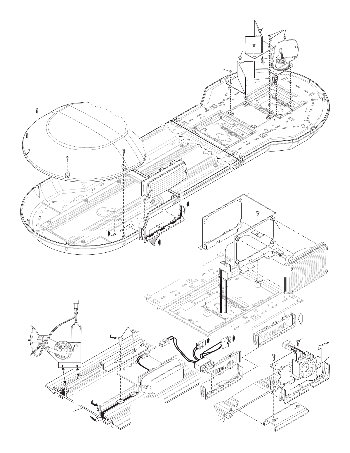
Servicing your Lightbar:
R
To power
distribution
board
Connect to
other MR11
Remove protective
backing from tape
before mounting
Secure bracket to
extrusion using
supplied sheet
metal screws
Insert grommets
into extrusion
500 Series
Lighthead
500 Series
Lighthead
Dome
400 Series
Lighthead
400 Series
Lighthead
MR11 TIR3
Flasher
Dome
6 X 3/4"
PPHSMS
410 / SS
8-32 X 3/4
PPHMS
BASE
EXTRUSION
FRONT
BRACKET
REAR
BRACKET
INSIDE
COVER
NOTE: If you need to remove
the oscillator from the lightbar
you must re-mount it in the
exact same position.
Hook bracket
over extrusion.
Secure bracket to
fastex grommets
installed into
base.
Secure bracket to
fastex grommet
installed into
base.
This section covers the removal and installation
of the components of your lightbar for repair or
replacement purposes. All options plug into the
distribution module which is mounted on the
base extrusion on the lower level. The sockets
on the distribution module are labeled for easy
Fastex
grommet
Mounting
bracket
Connector plugs
into distribution
module on lower
level.
Dome:
Removal:
Installation:
The domes are held on by 8-32x1/2" phillips pan head metal screws
Remove the dome mounting screws and Pull dome(s) off.
Place dome on lightbar base making sure it sits properly.
Secure dome(s) with supplied 8-32 X 1/2 Inch metal screws.
RUBBER
BUMPER
Hook bracket
over extrusion
here.
500 Series:
.
1.
2.
3.
NOTE: A is MR11,
Slide lighthead into retainer and remove backing from double sided tape on bottom.
Insert tabs on back of retainer into slots in lightbar base ress down
Reinstall upper cover. The 3 tabs on top of the lighthead will fit into 3 slots in the cover.
.
500 Series LED shown. 500 Series 5MM, 500 Series HALOGEN
500 SERIES TIR, LR11's and Flashers mount the same.
P so tape will stick.
The oscillator mounts
directly to two fastex
grommets inserted into
the extrusion.
The oscillator
does not use a
mounting bracket.
Oscillator:
500 Series:
Lighthead slides
into slots in retainer
Insert retainers tabs
into slots in the base
Insert retainers tabs
into slots in the base
400 Series:
Install 4 grommets into
the mounting bracket &
1 into the cover
the lightbar.
Secure lighthead to
mounting bracket using
Secure bracket (with
lighthead) to base cover
using supplied sheet
metal screws
1.
1.
1.
2.
2.
3.
3.
3.
inside
of
lighthead lens screws.
and plug
1.
2.
3.
Install 4 grommets into
the mounting bracket &
1 into the cover
the lightbar.
inside
of
Secure lighthead to
mounting bracket using
lighthead lens screws.
Secure bracket (with
lighthead) to base cover
using supplied sheet
metal screws. .
400 Series:
Same as
500 Series
Flasher:
INSIDE
COVER
BOSSES
GROMMET
GROMMET
Oscillator
(
Top View
)
Oscillator
(
Top View
)
Flasher
1.
1.
2.
2.
2.
3.
Install the 2 grommets into the lightbar inside
cover to which the rotator will mount.
Secure the front of the rotator by slipping its base
over the 2 bosses protruding from the inside
ecure the rear to the grommets you
using the 2 supplied sheet metal screws.
The rotator plugs into the distribution board
on the lower level.
cover. S
installed
Rotator:
1.
2.
3.
Install the 2 grommets into the lightbar inside
cover to which the rotator will mount.
Secure the front of the rotator by slipping its base
over the 2 bosses protruding from the inside
cover. Secure the rear to the grommets you
installed using the 2 supplied sheet metal screws.
The rotator plugs into the distribution board
on the lower level.
Dome:
identification.
RUBBER
BUMPER
BASE
EXTRUSION
LR11
Slide
bracket
into
extrusion.
2 screws
to secure.
LR11
Alley:
1.
1.
TIR3:
1.
2.
3.
4.
Secure lighthead to front bracket
lighthead lens screws.
Insert 2 fastex grommets into extrusion.
Place lighthead/bracket onto extrusion.
Slip rear bracket over extrusion and
with 2 sheet metal screws.
using
secure
MR11 /
4.
Page 8
Page 9
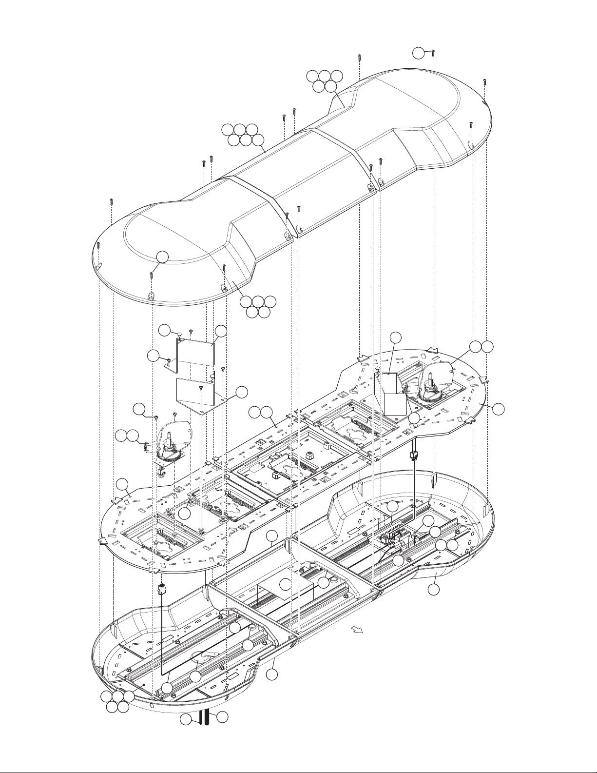
24
49
38
38
53
48
37
37
47
36
36
50
39
39
51
40
40
52
32
35
24
34
273028
31
26
30 31
35
14
14
19
15
32
34
17
33
3333
2929
FRONT OF LIGHTBAR
26
12
12
33
10
11
123
45
25
6
7
16
18
6059
Page 9
Page 10

NS = Not shown or hidden in parts drawing
ITEM
PART NUMBER DESCRIPTION
QTY QTY QTY QTYQTYQTYQTYQTYQTYQTY
NUT 10-24 CAD PLATED WHIZ//NS
2
1
3
5
4
7
6
11
10
9
8
14
12
13
18
16
15
19
20
21
2 STD ROT 72 11/16 DELTA IND. LIGHTBAR
2 STD ROT 61 13/16 DELTA IND. LIGHTBAR
2 STD ROT 56 5/16 DELTA IND. LIGHTBAR
2 STD ROT 49 3/4 DELTA IND. LIGHTBAR
2 STD ROT 44 5/16 DELTA IND. LIGHTBAR
HOUSING 1 POS 75A BLACK / POWERPOLE 75///
BRACKET MOUNTING PDM ASSYS / DELTA SERIES/
2 HI ROT 72 11/16 DELTA IND. LIGHTBAR
2 HI ROT 61 13/16 DELTA IND. LIGHTBAR
2 HI ROT 56 5/16 DELTA IND. LIGHTBAR
2 HI ROT 44 5/16 DELTA IND. LIGHTBAR
GROMET SPECIAL / 1.562 THERMOPLASTIC RUBBER/
GASKET EXTRUSION DELTA SERIES / 100' ROLL/
BOLT 10-24 X 1/2" CARRIAGE / STAINLESS STEEL/
LENS BASE CLEAR CORNER MODULE-DELTA
LENS BASE CLEAR DUAL-CENTER DELTA
CABLE CLAMP 5/8"D 1/2" W/.203 MTG HOLE BLK / NS
LENS BASE CLEAR SINGLE-CENTER DELTA
PLUG VENT .750 HOLE DIA BLACK/HEYCO/
BASE EXTRUSION MACHINED-DELTA42.00"/
BASE EXTRUSION MACHINED/DELTA36.531"/
2 HI ROT 49 3/4 DELTA IND. LIGHTBAR
BASE EXTRUSION MACHINED DELTA 48.612"/-
BASE EXTRUSION MACHINED DELTA 64.937"/-
BASE EXTRUSION MACHINED DELTA 54.062"/-
ELEC. HC PDM DELTA
WIRE 8 GA 20' BLACK / CONTACT/
SCREW 10-24 X 1" PPHMS//NS
ASS'Y CABLE 10/C COMPOSITE 20'/
DIVIDER with GASKET JOB 9077 DELTA
39-0001007-00
07-243110-000
01-0269815-00
11-363721-054
11-363721-048
01-0684131-09
01-0684131-08
01-0684131-07
01-0684131-06
01-0684131-02
01-0684131-04
01-0684131-03
01-0684131-05
11-363721-048
11-363721-054
11-363721-064
21-11245004-1B
21-7263998-00
38-0143029-00
02-0363798-00
14-104066-080
02-0384054-30
67-1N00800M00
02-0363812-30
02-0363813-30
14-104216-160
46-0743114-20
26-0115663-10
01-0684131-00
01-0684131-01
13-104120-062
16-1001220-06
01-5015970-29
01-0463929-01
01-0463929-00
46-0743399-00
10-0523072-02
68-4983959-10
68-4983959-20
68-4983959-30
68-4983959-90
68-4983960-10
68-4983960-20
68-4983960-30
68-4983960-90
68-4983958-10
68-4983958-20
68-4983958-30
68-4983958-40
08-0617449-00
02-0363716-00
11-283961-000
11-283979-000
11-283970-000
13-062C40-16J
68-5963707-D10
02-0363716-02
15-081416-060
68-5963707-P10
68-4983960-50
68-4983958-50
68-4983960-40
68-4983959-40
68-4983959-50
14-082216-080
13-104111-063
39-1V04017-00
46-0984112-00
09-1343082-00
36
29
24
23
22
25
28
27
26
30
32
31
35
34
33
40
39
38
37
43
42
41
47
46
45
44
50
49
48
1
2
1
1
24
10
4
2
1
2
1
3
1
1
1
A/R
A/R
16
1
1
4
1
-
2
3
2
-
4
2
16
2
A/R
A/R
A/R
A/R
A/R
A/R
A/R
A/R
A/R
A/R
1
24
A/R
2
A/R
24
24
1
2
1
1
24
9
4
2
2
1
1
2
1
1
1
1
A/R
A/R
16
1
1
4
1
2
2
1
2
-
4
2
16
2
A/R
A/R
A/R
A/R
A/R
A/R
A/R
A/R
A/R
A/R
A/R
A/R
A/R
A/R
A/R
A/R
24
1
A/R
2
A/R
24
24
1
2
1
1
24
8
4
2
1
2
1
3
1
1
1
A/R
16
1
1
4
1
3
2
-
2
-
4
2
16
2
A/R
A/R
A/R
A/R
A/R
A/R
A/R
A/R
A/R
A/R
A/R
1
24
A/R
A/R
2
24
24
1
2
1
1
16
7
2
2
1
2
1
1
1
1
1
A/R
A/R
16
1
1
4
1
-
2
1
2
-
4
16
2
2
A/R
A/R
A/R
A/R
A/R
A/R
A/R
A/R
A/R
A/R
A/R
24
A/R
1
16
16
1
2
1
1
16
6
2
2
1
2
1
1
1
1
1
A/R
16
1
1
1
4
1
2
-
2
-
4
16
2
2
A/R
A/R
A/R
A/R
A/R
A/R
A/R
A/R
A/R
A/R
A/R
24
1
A/R
A/R
16
16
1
2
1
1
24
10
4
2
1
2
1
3
1
1
1
A/R
A/R
16
1
1
1
4
-
2
3
2
4
-
2
16
2
A/R
A/R
A/R
A/R
A/R
A/R
A/R
A/R
A/R
A/R
1
24
A/R
2
A/R
24
24
2
1
1
2
2
2
24
9
4
1
1
1
1
1
1
1
A/R
A/R
4
-
2
2
16
16
2
2
2
4
1
1
1
1
A/R
A/R
A/R
A/R
A/R
A/R
A/R
A/R
A/R
A/R
A/R
A/R
A/R
A/R
24
24
A/R
A/R
A/R
2
A/R
24
1
54
58
53
57
52
51
56
60
55
59
1
2
1
1
24
8
4
2
1
2
1
3
1
1
1
A/R
16
1
1
1
4
3
2
-
2
4
-
2
16
2
A/R
A/R
A/R
A/R
A/R
A/R
A/R
A/R
A/R
A/R
A/R
1
24
A/R
2
A/R
24
24
1
2
1
1
16
7
2
2
2
1
1
1
1
1
1
A/R
A/R
16
1
1
4
1
-
2
1
2
4
-
2
16
2
A/R
A/R
A/R
A/R
A/R
A/R
A/R
A/R
A/R
A/R
16
1
A/R
A/R
16
16
1
2
1
1
16
6
2
2
1
2
1
1
1
1
1
A/R
16
1
1
1
4
1
2
-
2
4
-
2
16
2
A/R
A/R
A/R
A/R
A/R
A/R
A/R
A/R
A/R
A/R
A/R
A/R
A/R
1
16
16
16
DOME BLUE CTR MODULE DUAL / DELTA SERIES/
DOME CLEAR CTR MODULE DUAL / DELTA SERIES/
DOME BLACK CTR MODULE DUAL / DELTA SERIES/
DOME AMBER CTR MODULE SINGLE / DELTA SERIES/
DOME BLUE CTR MODULE SINGLE / DELTASERIES/
DOME CLEAR CTR MODULE SINGLE / DELTASERIES/
DOME BLACK CTR MODULE SINGLE / DELTASERIES/
ASS'Y ROTATING REFL 175-12-H1 DELTA SERIES/
COVER INSIDE CENTER DUAL / DELTA SERIES/
COVER INSIDE CORNER BLACK / DELTASERIES/
COVER INSIDE CENTER SINGLE / DELTASERIES/
ASS'Y ROTATING REFL 150-12-H1 DELTA SERIES/
ASS'Y MIRROR PASSENGER SIDE / DELTA SERIES/
DOME RED CTR MODULE SINGLE / DELTASERIES/
DOME GREEN CTR MODULE SINGLE / DELTASERIES/
DOME GREEN CTR MODULE DUAL / DELTA SERIES/
DOME RED CTR MODULE DUAL / DELTA SERIES/
ASS'Y HARNESS I O C ROT LED / DELTA SERIES/---
PANEL WIRE MANAGEMENT / DELTA LIGHTBAR/
HOUSING 4 POS PLUG / UNIVERSAL MATE N LOK//NS
DOME RED CORNER MODULE/
BUMPER, GROMMET STYLE RUBBER / BLACK
SCREW GROMMET #6/#8 FASTEX
SCREW 8 X 3/8 PPHSMS / 410 SS/
ASS'Y MIRROR DRIVER SIDE / DELTA SERIES/
DOME AMBER CORNER MODULE/
DOME BLUE CORNER MODULE/
DOME CLEAR CORNER MODULE/
DOME GREEN CORNER MODULE/
KIT 3M 792 OPTICOM MOUNTING CABLE DELTA/ / with /
DOME AMBER CTR MODULE DUAL / DELTA SERIES/
WASHER #10 FLAT 18-8 STAINLESS//
NUT / 10-24 ELASTIC STOP STAINLESS/
MODEL 792H OPTICOM EMITTER / NS
KIT 3M 792 OPTICOM MOUNTING DELTA///NS
HARNESS EXTENSION DELTAROT/LED/
LABEL M N S N DELTA SERIES "HC" MODEL/--- /NS
SCREW 8-32 X 1/2 PPHMS SS//NS
Page 10
 Loading...