

Page 1

®
ENGINEERING COMPANY INC.
51 Winthrop Road
Chester, Connecticut 06412-0684
Century™ Wrecker Lightbar
Installation Guide:
Phone: (860) 526-9504
Fax: (860) 526-4078
Internet: www.whelen.com
Sales e-mail: autosale@whelen.com
Canadian Sales e-mail: canadiansales@whelen.com
Customer Service e-mail: custserv@whelen.com
Safety First
This document provides all the necessary information to allow your Whelen product to be properly and safely installed.
Before beginning the installation and/or operation of your new product, the installation technician and operator must
read this manual completely. Important information is contained herein that could prevent serious injury or damage.
• Proper installation of this product requires the installer to have a good understanding of automotive electronics,
systems and procedures.
• Failure to use specified installation parts and/or hardware will void the product warranty!
• If mounting this product requires drilling holes, the installer MUST be sure that no vehicle components or other
vital parts could be damaged by the drilling process. Check both sides of the mounting surface before drilling
begins. Also de-burr any holes and remove any metal shards or remnants. Install grommets into all wire
passage holes.
• If this manual states that this product may be mounted with suction cups, magnets, tape or Velcro®, clean the
mounting surface with a 50/50 mix of isopropyl alcohol and water and dry thoroughly.
• Do not install this product or route any wires in the deployment area of your air bag. Equipment mounted or
located in the air bag deployment area will damage or reduce the effectiveness of the air bag, or become a
projectile that could cause serious personal injury or death. Refer to your vehicle owner’s manual for the air bag
deployment area. The User/Installer assumes full responsibility to determine proper mounting location, based
on providing ultimate safety to all passengers inside the vehicle.
• For this product to operate at optimum efficiency, a good electrical connection to chassis ground must be
made. The recommended procedure requires the product ground wire to be connected directly to the NEGATIVE
(-) battery post.
• If this product uses a remote device to activate or control this product, make sure that this control is located in
an area that allows both the vehicle and the control to be operated safely in any driving condition.
• Do not attempt to activate or control this device in a hazardous driving situation.
• This product contains either strobe light(s), halogen light(s), high-intensity LEDs or a combination of these
lights. Do not stare directly into these lights. Momentary blindness and/or eye damage could result.
• Use only soap and water to clean the outer lens. Use of other chemicals could result in premature lens cracking
(crazing) and discoloration. Lenses in this condition have significantly reduced effectiveness and should be
replaced immediately. Inspect and operate this product regularly to confirm its proper operation and mounting
condition. Do not use a pressure washer to clean this product.
• It is recommended that these instructions be stored in a safe place and referred to when performing
maintenance and/or reinstallation of this product.
• FAILURE TO FOLLOW THESE SAFETY PRECAUTIONS AND INSTRUCTIONS COULD RESULT IN DAMAGE TO
THE PRODUCT OR VEHICLE AND/OR SERIOUS INJURY TO YOU AND YOUR PASSENGERS!
Automotive: Lightbars
For warranty information regarding this product, visit www.whelen.com/warranty
©2012 Whelen Engineering Company Inc.
Form No.14591 (052312)
Page 1
Page 2
WHT
RED
GRN
BLACK
RED
RED/WHT
BLK
BLK/WHT
BLK
BLUE
WHITE
GREEN
ORANGE
RED
(+) TAIL LIGHT
(+) LEFT TURN
(+) RIGHT TURN
(-) GROUND
(+) FRONT LEDS
(+) REAR LEDS
(-) FRONT LEDS
(-) REAR LEDS
GROUND
LOW POWER
(+) WORKLIGHT
(+) PATTERN OVERIDE
(+) AUX / UNUSED
(+) SCANLOCK
Wire Function
BRAKE-TAIL-TURN
Fuse
10 Amp
10 Amp
5 Amp
1 Amp
1 Amp
1 Amp
All fuses and
switches are
customer
supplied
BATTERY
SPST Switches
SPST Switches
Momentary Switch
Century Wrecker Lightbar
WHT (-) GND
BRN (+) TAIL
YEL (+) TURN
WHT (-) GND
BRN (+) TAIL
YEL (+) TURN
RIGHT - BRAKE
TAIL TURN LIGHT
LEFT - BRAKE
TAIL TURN LIGHT
TO GROUND (BLK)
TO TAIL (WHT)
TO LEFT TURN (RED)
TO GROUND (BLK)
TO TAIL (WHT)
TO RIGHT TURN (GRN)
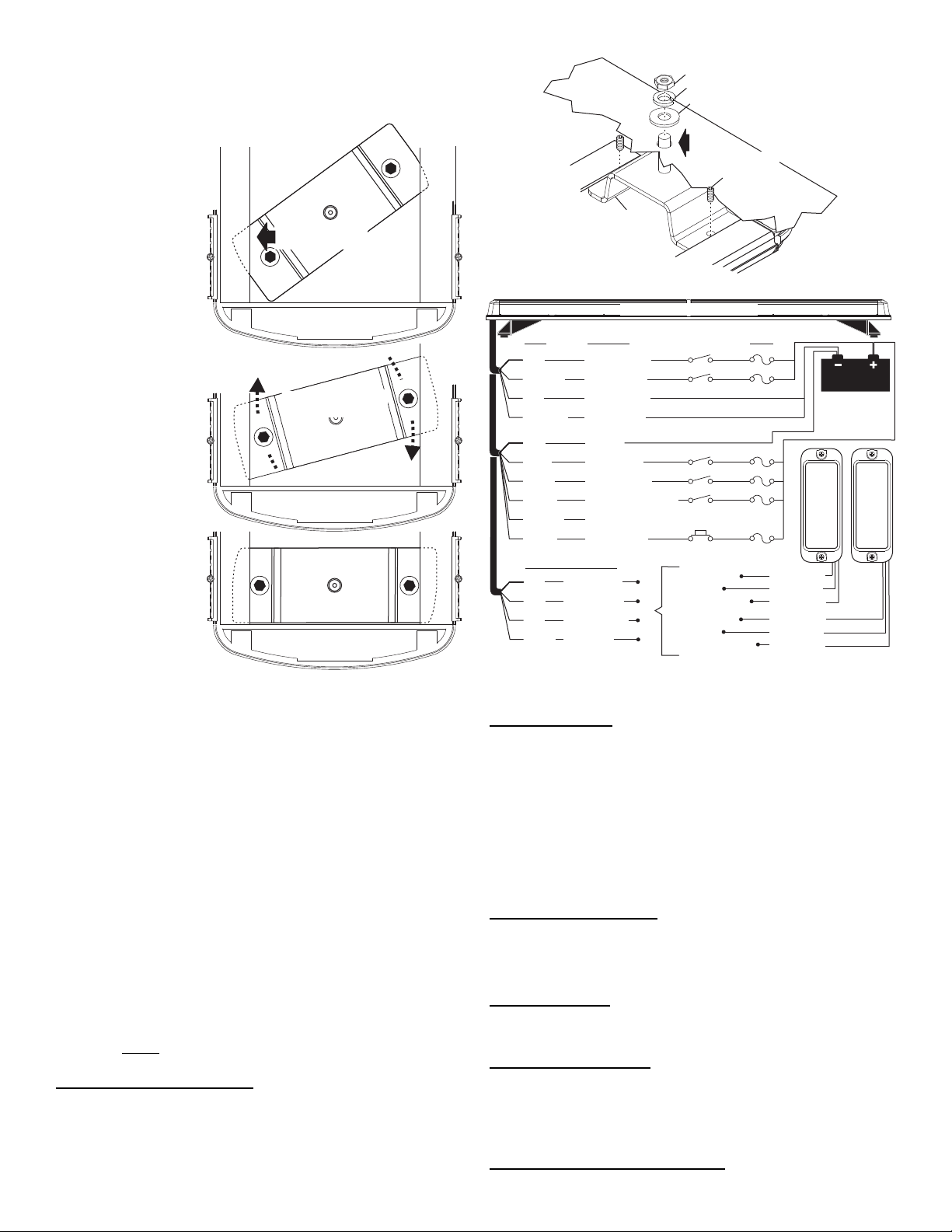
IMPORTANT! The lightbar should be a minimum
3/8" FLAT WASHER (1)
1/4 - 20 X 1/2
ALLEN SET
SCREW (1)
STUD MOUNT
BRACKET (1)
STUD MOUNT
MOUNTING
SURFACE
3/8"
mounting
hole
3/8" SPLIT LOCK WASHER (1)
3/8 - 16 HEX NUT (1)
Secure bracket with
allen set screws
Insert rounded end
under lip in extrusion
Swing opposite end
under other lip
of 16" from any radio antennas!
Permanent Mounting / Stud Mount:
Caution: Permanent
mounting of this product
will require drilling. Be
absolutely sure that no
other vehicle
components could be
damaged by this
process. Check both
sides of the mounting
surface before starting. If
damage is likely, select a
different mounting
location.
1. Insert the 2 Stud
2. Make sure that the
3. Place the lightbar in
4. Remove the lightbar and drill the mounting holes as well as the 5/16” dia.
5. Route the wires through the grommet and to the necessary switches and
6. Secure the lightbar to the vehicle using the hardware provided. From the
IMPORTANT! It is the responsibility of the installation technician to make
sure that the installation and operation of this product will not interfere
with or compromise the operation or efficiency of any vehicle equipment!
Before returning the vehicle to active service, visually confirm the proper
operation of this product, as well as all vehicle components/equipment.
Lightbar Cables:
This lightbar uses a 4-conductor cable for LEDs and a 6 conductor cable for options.
There is also a 4 conductor cable for BRAKE-TAIL to connect to your brake lights.
Extend the 4 and 6 conductor LED and FUNCTION cables towards your switch
panel. The instructions included with your switches will provide switch wiring
information. The BRAKE-TAIL cable connects to the brake lights.
WARNING! All Customer supplied wires that connect to the positive terminal of
the battery must be sized to supply at least 125% of the maximum operating
current and FUSED
BREAKERS WITH THIS PRODUCT!
6 Conductor Option Cable:
WHITE: Apply +12 volts to activate the Worklight
GREEN: Apply +12 volts to activate Pattern Override
RED: Apply +12 volts to activate Scan-Lock™
BLUE: Apply +12 volts to activate Low Power.
Mount brackets under
the lip in the bottom of
the extrusion.
(rounded end first)
and pivot the bracket
so that the other end
slides under the other
lip in the extrusion.
brackets are sitting all
the way at each end
of the extrusion, then
secure them with the
supplied allen set
screws.
the exact mounting
location. Mark the
location of the 2
mounting holes onto
the mounting surface,
and the area for the
wire passage hole.
This hole should be
located directly below where the wires exit the extrusion.
wire passage hole. De-burr all the holes and install a rubber grommet
(customer supplied) into the wire passage hole.
power source as shown in the wiring diagram.
underside of the mounting surface, apply RTV around each mounting
hole and the grommeted wire passage hole.
at the battery to carry that load. DO NOT USE CIRCUIT
ORG: Available to add option / + 12 volts to activate / Fuse appropriately
BLACK: Ground
RED: Scan-Lock™
LED’s must be on for Scan-Lock™ to work.
TO CHANGE PATTERNS: To cycle forward to the next available pattern: Apply +12
volts to the RED wire for less than 1 second and release. To cycle back to the
previous pattern: Apply +12 volts to the RED wire for over 1 second and release.
TO CHANGE THE DEFAULT PATTERN: Allow the desired pattern to run for more
than 5 seconds. The lighthead will now display this pattern when activated.
TO RESTORE THE FACTORY DEFAULT PATTERN: With power to the lightheads
off, apply +12 volts to the RED wire. While still applying +12 volts to the RED wire,
turn power to the lightheads back on and the factory default pattern will be displayed.
A normally open momentary switch can be used to control Scan-Lock™.
GREEN: Pattern Override
Applying +12 volts to the GREEN wire while lightheads are activated will change the
flash pattern to whatever “pattern override” is programmed for. To program the flash
pattern activate the lightbar. Activate pattern override by applying +12 volts to the
GREEN wire then select a flash pattern using the Scan-Lock™ procedure.
BLUE: Low Power
Applying +12 volts DC to the BLUE wire for more than 1 second holds the lightbar in
low power mode until that voltage is removed. A toggle switch is best suited for this.
4 Conductor LED Cable:
RED: Apply +12 volts to activate the Front LED’s
RED/WHT: Apply +12 volts to activate the Rear LED’s
BLACK: Ground wire for Front LED’s
BLK/WHT: Ground wire for Rear LED’s
4 Conductor Brake-Tail-Turn Cable: Connect as shown above.
Page 2
Page 3

CAUTION! DO NOT LOOK DIRECTLY AT THESE LEDS WHILE THEY ARE ON.
MOMENTAR Y BLINDNESS AND/OR EYE DAMAGE COULD RESULT!
IMPORTANT WARNING!
44
1
4
5
3
2
20
22
19
18
32
33
17
21
14
15
16
38
34
39
3637
35
01-0687191-__
01-0687191-__
ITEM
PART NUMBER
DESCRIPTION
QTY QTY
GROMMET, 1.562" THERMOPLASTIC RUBBER
21-11245004-1
PLUG, VENT .750 DIA HOLE LIGHTBAR
21-7263998-00
SCREW, 10-24 X 1" PPHMS SS
14-104216-160
CABLE CLAMP, 5/8"D, 1/2"W .203" MTG HOLE, BLACK
26-0115663-10
NUT, 10-24 CAD PLATED WHIZ OR STEEL ZINC PLATED
13-104111-063
46-0710479-18
ASS'Y, 6/C 16 GA 18' CABLE STRIP 4"W/61117/STRIP 2
01-0687191-__
CENTURY WRECKER LTBAR 56"
CENTURY WRECKER LTBAR 60"
CENTURY WRECKER LTBAR 72"
11-36D421-053
EXTRUSION, MACHINED, 53.700" CENTURY
11-36D421-057
EXTRUSION, MACHINED, 57.100" CENTURY
11-36D421-069
EXTRUSION, MACHINED, 69.740" CENTURY
1
1
1
1
2
1
1
1
1
1
2
1
1
1
1
2
1
1
1
11
111
02-0241912-00
ASS'Y, INPUT CABLE BRAKE/TAIL LIGHT
111
46-0743513118
ASS'Y, CABLE 4/C 14 GA 18' W/CMNL SOCKETS
QTY
2
3
11
4
5
6
7
8
9
10
1
GROMMET, PLASTI- #8/10 .275-.290 SQ HOLE, .057 HD HT
21-17060704-3
SCREW, 8 X 1/2 PPHSMS 410 SS
15-081416-080
20
24
202420
24
15
16
SUB ASSY, CENTURY WRECKER I/O
01-026D819-00
111
111
39-0412023-04
HOUSING, 12 POS SCKT F/H COMM MATE-N-LOK
13
14
TY WRAP, 6" BLACK
26-0215001-06
111
12
SUB ASSY, 6 LED CORNER AMB/AMB CENTURY LIGHTBAR
01-026D523111
SUB ASSY, LR11 TAKE DOWN LIGHT CENTURY LIGHTBAR
01-026D367-30
14-040285-063
SCREW, 4-40 X 3/8 TORX PH TRILOBULAR 410 SS, BLK OXIDE
07-76D682-000
PLATE, CORNER MOUNT DUAL L32 CENTURY LIGHTBAR
222
222
222
222
17
18
19
20
SUB ASSY, 5mm LED B/T/T CENTURY LTBAR
01-026D804-00
SCREW, 10-24 X 1.25" WAX DIP SHOULDER PHTX TRI PT SS
14-104286-16J
SEAL, EXTRUDED CENTURY LTBAR
38-0523713-00
DOME, CLEAR OPTIC OPEN END CENTURY LIGHTBAR
68-1986987-30
SEAL, DIVIDER CENTURY LIGHTBAR
38-046D289-00
DIVIDER, LENS CENTURY LIGHTBAR
38-046D288-00
19-36D291-000
CLAMP, SLIDE-LOCK LENS MOUNT CENTURY LIGHTBAR
26-0215001-03
TY WRAP, 3" BLACK
10-0322935-00
LABEL, "FRONT" LIGHTBAR ASSYS
10-0523732-00
LABEL, MODEL & SERIAL NO. CENTURY
15-04541A-080
SCREW, 4 X 1/2 PPH PLASTILOC ZINC BLACK, SS
222
111
A/RA/R A/R
02-0344217-00
SUB ASSY ENDCAP, CENTURY LIGHTBAR
222
444
131.25"
156.5" 124.5"
222
2
2
68-196D587-30
DOME, CLEAR SINGLE CTR 6.062" CENTURY LIGHTBAR
68-196D589-30
11
6
3
4
2
8
4
161620
444
1111
11
46-0784802-02
ASS'Y, HARNESS HALOGEN 54" JUSTICE SERIES
1 1
46-0941911-00
ASS'Y, BRAKE/TAIL LT HARNESS
DOME, CLEAR DUAL CTR 15.675 CENTURY LIGHTBAR
333
02-0344251-00
ASSY, BRACKET STUD MOUNT CENTURY W/ 1-1/2" STUD
444
01-026E017-10
SUB ASSY, 12LED LTHEAD AMBER CENTURY LIGHTBAR
1
1
1
46-0787208-00
ASSY, HARNESS REAR, 56" CENTURY WRECKER
46-0787208-01
ASSY, HARNESS REAR, 60" CENTURY WRECKER
46-0787208-02
ASSY, HARNESS REAR, 72" CENTURY WRECKER
1
1
1
46-0784978-00
46-0784978-01
46-0784978-02
ASS'Y, HARNESS FRONT 42" JUSTICE WC
ASS'Y, HARNESS FRONT 48-54" JUSTICE WC
ASS'Y, HARNESS FRONT 60" JUSTICE WC
ASS'Y, BRAKE/TAIL LT HARNESS, EXTRA LENGTH
46-0941911-01
1
21
22
30
31
32
33
34
35
36
37
38
39
23
24
25
26
27
28
29
40
41
42
43
44
45
1. ActionScan™
2. SignalAlert™ Alt.
3. SignalAlert™ Alt./ASync
4. SignalAlert™Sim.
5. SignalAlert™ Alt./Sim.
6. CometFlash® Alt.
7. CometFlash® Alt./ASync
8. CometFlash® Sim.
9. CometFlash® Alt./Sim.
10. DoubleFlash 75 Alt.
11. DoubleFlash 75 Alt./ASync
12. DoubleFlash 75 Sim.
13. DoubleFlash 75 Alt./Sim.
14. SingleFlash 75* Alt.
15. SingleFlash 75* Alt./ASync
16. SingleFlash 75* Sim.
17. SingleFlash 75* Alt.Sim.
18. LongBurst™ Alt.
19. LongBurst™ Alt./ASync.
20. LongBurst™ Sim.
21. LongBurst™ Alt./Sim.
22. SingleFlash 60* Alt.
23. SingleFlash 60* Alt./ASync.
24. SingleFlash 60* Sim.
25. SingleFlash 60* Alt./Sim.
26. SingleFlash 90* Alt.
27. SingleFlash 90* Alt./Sync.
28. SingleFlash 90* Sim.
29. SingleFlash 90* Alt./Sim.
30. SingleFlash 120* Alt.
31. SingleFlash 120* Alt./Sync.
32. SingleFlash 120* Sim.
33. SingleFlash 120* Alt./Sim.
34. SingleFlash 300 Alt.
35. SingleFlash 300 Alt./Sync.
36. SingleFlash 300 Sim.
37. SingleFlash 300 Alt./Sim.
38. MicroBurst™ Alt.
39. MicroBurst™ Alt./ASync.
40. MicroBurst™ Sim.
41. MicroBurst™ Alt./Sim.
42. ActionFlash™ Alt.
43. ActionFlash™ Alt./ASync.
44. ActionFlash™ Sim.
45. PingPong™ Alt.
46. PingPong™ Alt./ASync.
47. FlimFlam Alt.
48. FlimFlam Alt./ASync.
49. ModuFlash™ Alt.
50. ModuFlash™ Alt./ASync.
51. ModuFlash™ Sim.
52. ZigZag.
Alt.= Alternating Sim. = Simultaneous Alt./Sim. = Alternating/Simultaneous Alt./ASync. = Alternating/ASynchroneous
IMPORTANT! Before returning this vehicle to active service, visually confirm
the proper operation of this product, as well as all vehicle components/
equipment.
* = California Title IIIX Compliant
IMPORTANT! It is the responsibility of the installation technician to make sure
that the installation and operation of this product will not interfere with or
compromise the operation or efficiency of any vehicle equipment!
Page 3
 Loading...