

Page 1
PROGRAMMING GUIDE
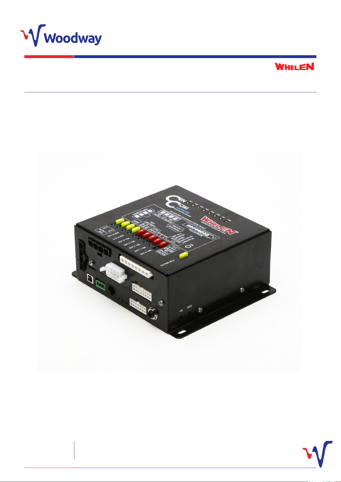
CenCom Sapphire™
Woodway Engineering Ltd
Lower Road, Barnacle
Coventry, CV7 9LD
United Kingdom
Tel: +44 (0) 24 76 841750
Fax: +44 (0) 24 76 621796
[email protected]
www.woodwayengineering.com
Page 2
PC System Requirements
CenCom Sapphire™ UK is Whelen’s newest evolution of the
CenCom family of software. It allows you to program your
CenCom Sapphire™ hardware, including programming your
Additional Prerequisites:
• Windows Installer 3.1
• .NET framework 3.5 (automatically checked during
installation).
WeCan® compatable lightbar.
PC System requirements:
• Microsoft Windows XP, with SP2, Windows Vista, Windows 7
or Windows 8.
• 500MB of RAM (1GB recommended)
• 25MB of available hard disk space.
Introduction
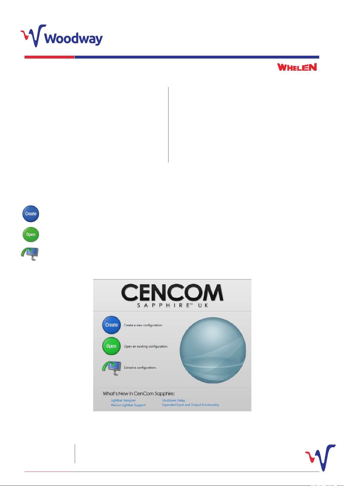
On opening the CenCom Sapphire™ UK programming software, the initial start up menu will be shown. You will be presented with the
following options:
This can be selected if you wish to create a whole program for your CenCom Sapphire™ UK from the start.
This is used to open an already created and saved program le. Select this if there is already a program created and
you just wish to alter it
This allows you to copy a program le direct from the CenCom Sapphire™ UK, and ensures the exact settings from
that unit are used.
Woodway Engineering Ltd
Lower Road, Barnacle
Coventry, CV7 9LD
United Kingdom
Tel: +44 (0) 24 76 841750
Fax: +44 (0) 24 76 621796
[email protected]
www.woodwayengineering.com PROGRAMMING GUIDE
2
Page 3
Creating a New Program
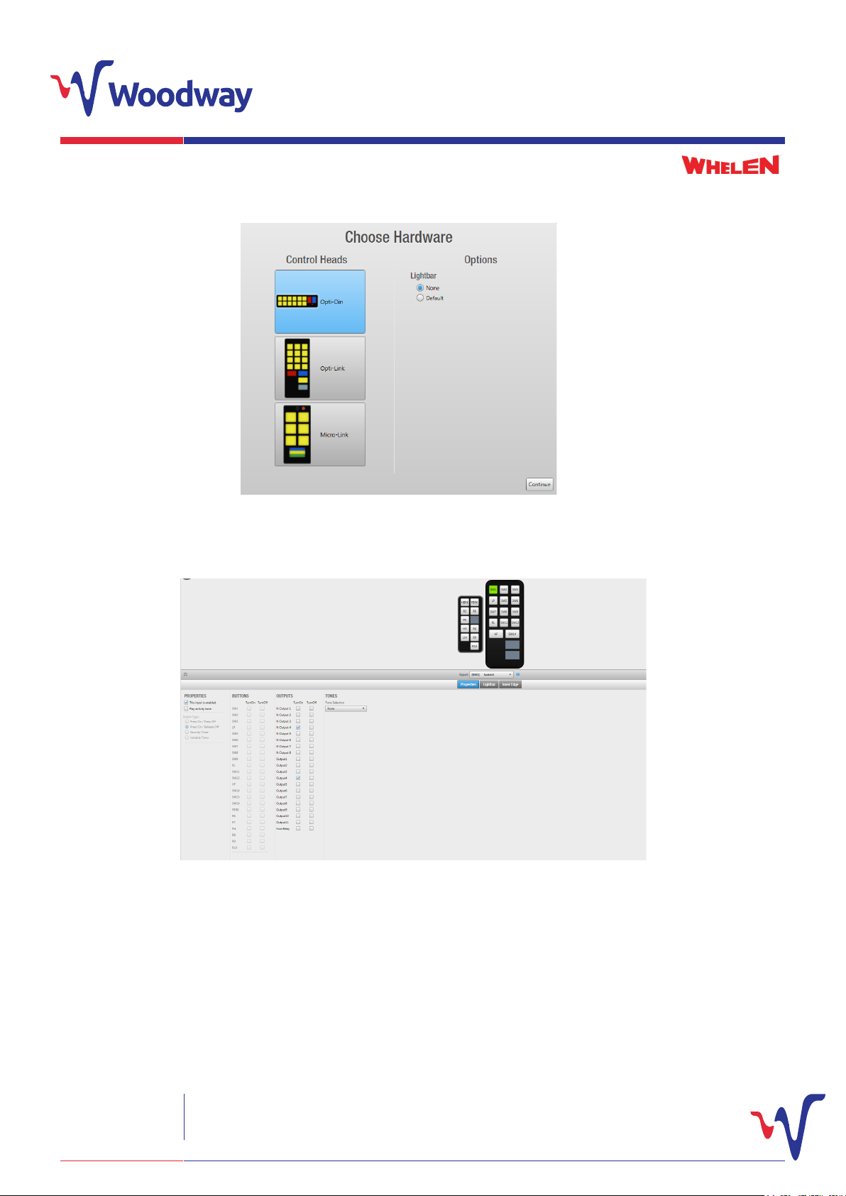
Select ‘create’ to start a new program. From here. you will need to select which switch panel you intend to use with your unit.
Ensure ‘none’ is selected
Once you have selected the switch panel you’re using, ensure the ‘lightbar’ option is set to ‘none’ (you can upload a lightbar
conguration separately, later on).
Once completed, click ‘continue’’. Following on from this, the program’s interface window will then be shown:
Outputs
Properties of
switch inputs
This window should show:
1. The selected control head (E.G Opti-Link)
2. A representation of the remote inputs (E.G R1, R2) for ease of programming
3. The properties of the switches and inputs (E.G press on, press o)
4. The outputs that can be set to be activated or deactivated by them.
When the control head is selected, the default settings for this will be automatically loaded with outputs set to activate with preselected
control head switches and remote inputs.
Woodway Engineering Ltd
Lower Road, Barnacle
Coventry, CV7 9LD
United Kingdom
Tel: +44 (0) 24 76 841750
Fax: +44 (0) 24 76 621796
[email protected]
www.woodwayengineering.com PROGRAMMING GUIDE
3
Page 4
Creating a New Program (continued)
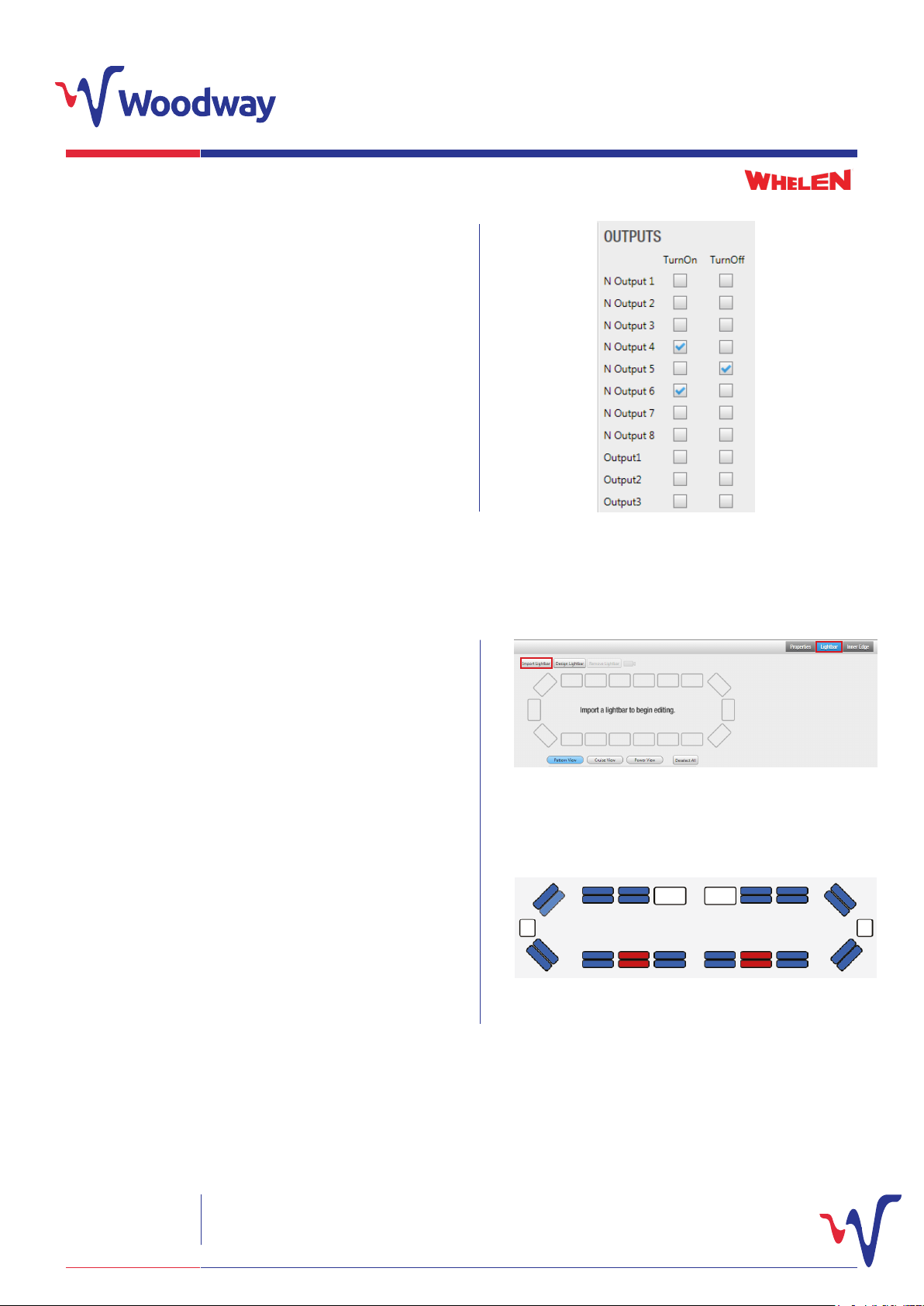
Clicking on a switch (E.G SW1) on the control head or remote
input (R1) will allow you to view and alter any of the outputs set to
activate or deactivate.
Select a switch (E.G SW1) or input (E.G R1), then simply select the
outputs that you wish to turn on or o by selecting the tickbox.
Multiple outputs can be selected for each individual switch or
input.
To deselect an output that you do not want to use, then simply
remove the tick from the box.
Programming Lightbar Functions
To program lightbar functions, you need to upload a .bxr WeCad le
for the bar being used with the CenCom Sapphire™ UK unit.
1. To upload the .bxr le, click on the ‘Lightbar’ tab.
2. Click ‘Import Lightbar’. This will bring up Windows Explorer
navigation pnae. Navigate to where you have saved the .bxr le you
would like to use. Select the le and click ‘open’.
3. Once uploaded, a representation of the lightbar will be shown on
screen.
4. To set the lightbar, there are 3 dierent views that can be
selected: ‘Pattern View’, ‘Cruise View’ and ‘Power View’.
The .bxr le can be created using WeCAD software which is available
from the Whelen webiste: www.whelen.com/eng_apps/index.php
Woodway Engineering Ltd
Lower Road, Barnacle
Coventry, CV7 9LD
United Kingdom
Tel: +44 (0) 24 76 841750
Fax: +44 (0) 24 76 621796
[email protected]
www.woodwayengineering.com PROGRAMMING GUIDE
4
Page 5
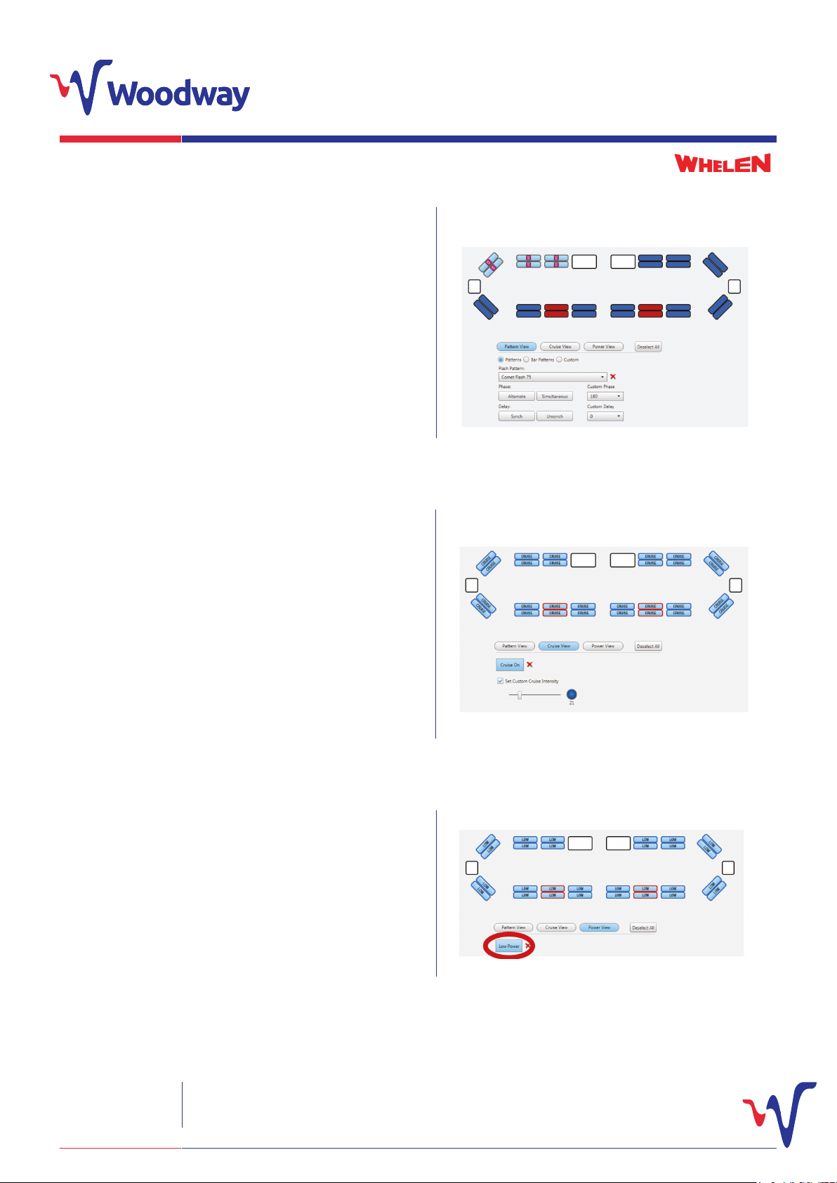
Pattern View
The ‘Pattern View’ is used to set the ash patterns of the lightbar
lightheads that will be used during the normal operation of the bar
and vehicle.
Each lighthead can be programmed to activate by a control head
switch or remote input. The ‘Flash Pattern’, ‘Phase’ and ‘Delay’ can
be set for each lamp using drop down menus.
To set, simply select a control head switch or remote input and
select desired lightheads you wish to activate (multiple lightheads
can be selected). To select, simply click on a lighthead.
Cruise View
This is used to select the required lightheads and light intensity used
during ‘Cruise Mode’.
Select the desired control head switch or external input you wish to
activate cruise mode. Then select the lightheads you wish to have
active and press ‘Cruise On’. The word ‘Cruise’ will then appear in any
of these selected lightheads.
Clicking ‘Set Custom Cruise Intensity’ will bring up the on screen
slider. This is used to alter the itensity of the lightheads during cruise
operation.
Power View (Low Power Setting)
The ‘Power View’ is used to select the lightheads required for low
power mode.
Left click on the desire switch on the control head and select ‘Low
Power’ from the list. This will then appear as LP on the control
head. Then select the lightheads you wish to set to low power, once
selected click the ‘Low Power’ as shown in the diagram.
Woodway Engineering Ltd
Lower Road, Barnacle
Coventry, CV7 9LD
United Kingdom
Tel: +44 (0) 24 76 841750
Fax: +44 (0) 24 76 621796
[email protected]
www.woodwayengineering.com PROGRAMMING GUIDE
5
Page 6
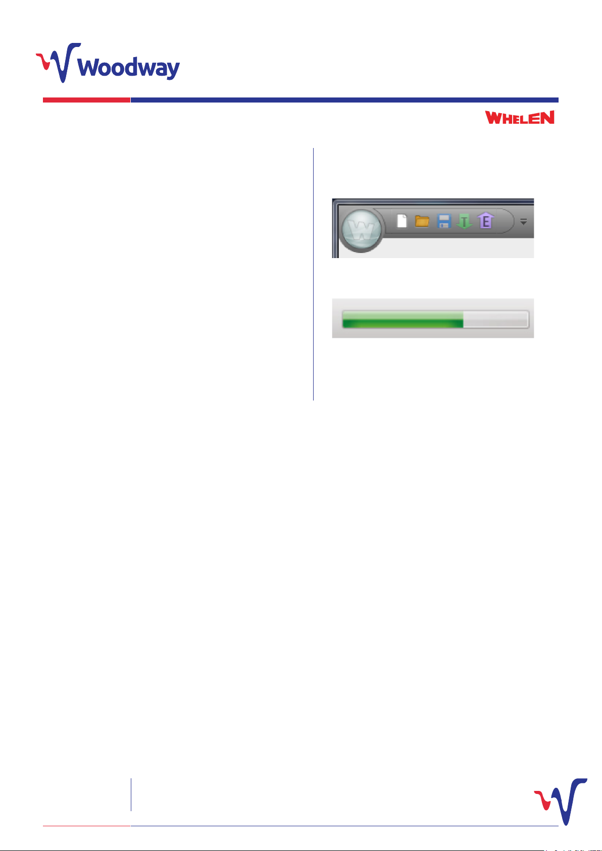
Transferring Program to CenCom Sapphire™ Unit
Before transferring to the CenCom Sapphire™ UK unit, it’s
recommended you save your completed program.
To transfer your completed program to your CenCom Sapphire™
UK unit, it must be disconnected from any power source and
connected to your computer using a USB type A- USB type B
programming lead.
Once the CenCom Sapphire™ UK is connected, simply press the
green transfer icon in the top left corner of the screen.
A green status bar will then appear in the bottom right of the
screen showing the transfer to the CenCom Sapphire™ UK.
Once this has nished, a window will appear, prompting you to
disconnect the CenCom Sapphire™ UK from the computer.
Your CenCom Sapphire™ UK is programmed and ready to use.
Default Settings
The CenCom Sapphire™ UK programming software has default settings applied when it is rst opened. These include:
• The default setting for hands free is piercer
• When siren is sounding, output 9 is automatically activated for use as siren in use.
• The run lock is set for a default run time of 4 hours.
• When run lock is activated, outputs 6 &7 are automatically activated remote input 10 (R10) is default set as airhorn.
• Remote input 7 (R7) is default set for remote 999 activation.
• Shut down delay is default set at 30 minutes.
Certain outputs are also already set to activate or deactivate to certain control head switches and remote inputs.
For information on how to alter or remove these defaults as well as further expanded details on all sections covered within this guide,
please refer to the full Programming Manual, available from the product page on our website- www.woodwayengineering.com
Woodway Engineering Ltd
Lower Road, Barnacle
Coventry, CV7 9LD
United Kingdom
Tel: +44 (0) 24 76 841750
Fax: +44 (0) 24 76 621796
[email protected]
www.woodwayengineering.com PROGRAMMING GUIDE
6
Page 7
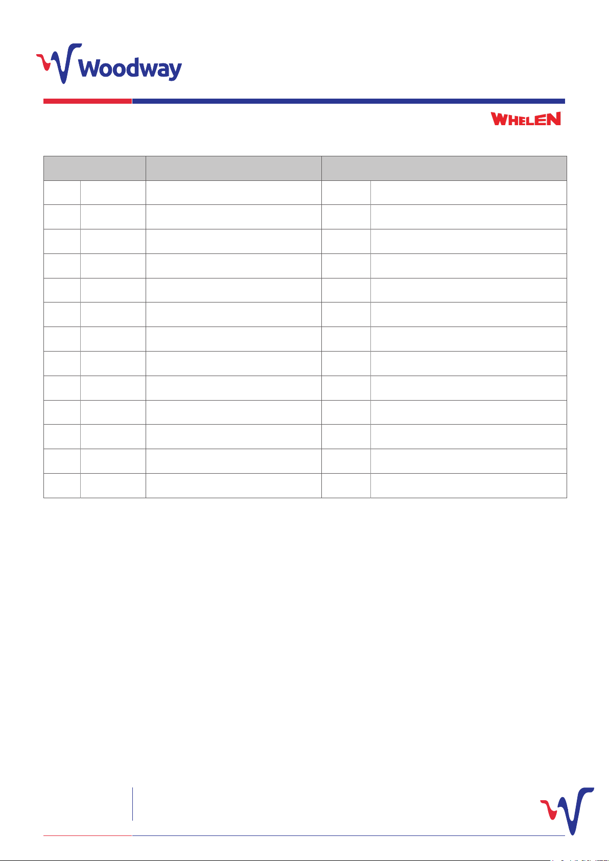
CenCom Sapphire™ UK Opti-Din Conguration Default Settings
SWITCH LEGEND FUNCTION OUTLETS
1 360 All lightbar blues & tailgate blues WeCan® 4 & N4
2 Front blues All lightbar front blues WeCan®
3 Low power Lightbar low power of all blues and reds WeCan®
4 Rear blues All lightbar rear blues and tailgate blues WeCan® 4 & N4
5 Headlight Vehicle headlight ash (separate asher) WeCan® 3
6 Rear reds Lightbar rear reds and tailgate reds WeCan® 5 & N5
7 Left alley Left alley light WeCan®
8 Right alley Right alley light
9 Run lock Vehicle run lock 4 hours 6 & 7 Default hidden
10 Take downs Take downs, steady WeCan®
11 Grille blues Grille blues 2
12 Dash light Dash ION light 10
13 Siren arm Hands free 9 Default hidden (IDR O/P)
Woodway Engineering Ltd
Lower Road, Barnacle
Coventry, CV7 9LD
United Kingdom
Tel: +44 (0) 24 76 841750
Fax: +44 (0) 24 76 621796
[email protected]
www.woodwayengineering.com PROGRAMMING GUIDE
7
Page 8
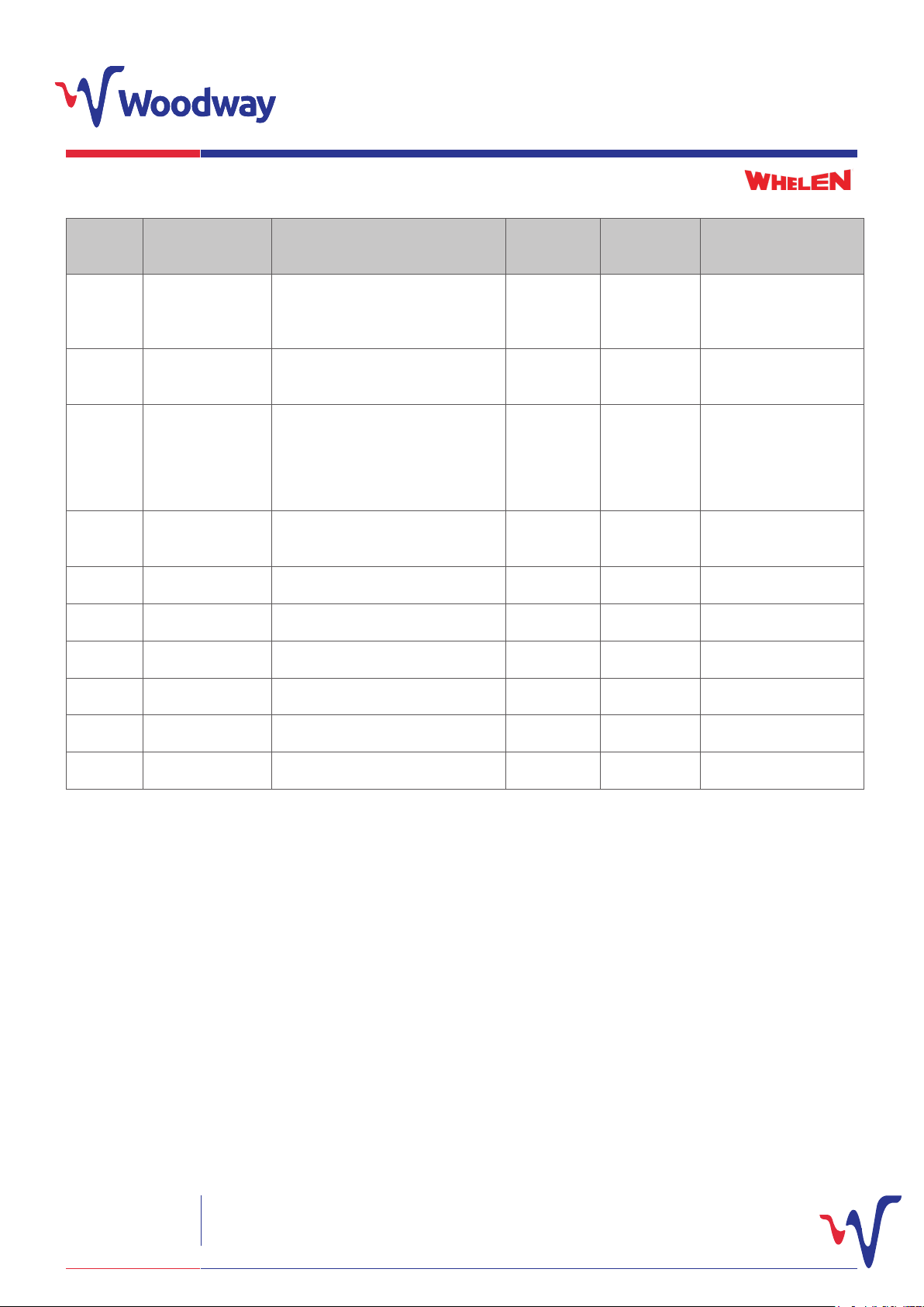
Additional Input Operations
INPUTS
R1
SWITCH/
FUNCTION
Handbrake
STRVU
R2 Tailgate switch
OPERATIONS
Turns run lock o and turns siren
test volume reduction if wired in
Turning on and o of tailgate
blues/reds
POLARITY
OF INPUT
Negative
Live
Using the CenCom™ shutdown
R3
Delayed outputs
for sockets or
radios etc.
delay timer keeps these circuits
alive once the ignition has been
Negative
turned o for the delay period set
R4 Horn Ring
Siren tone activation and tone
change
Live
R5 Foot brake Turns run lock o Live
R6 Input 6 No preset Live
R7 Remote 999 Live
Press on
release o
Press on
release o
Press on
release o
Press on
release o
OUTPUT
8 On (if run lock active,
this turns o 6&7)
N4 &N5
1 On
R8 Input 8 Negative
R9 Input 9 Negative
R10 Air horn Negative
Woodway Engineering Ltd
Lower Road, Barnacle
Coventry, CV7 9LD
United Kingdom
Tel: +44 (0) 24 76 841750
Fax: +44 (0) 24 76 621796
[email protected]
www.woodwayengineering.com PROGRAMMING GUIDE
8
Page 9
CenCom Sapphire™ Opti-Link conguration Default Settings
SWITCH LEGEND FUNCTION OUTLETS
WeCan® 2
1 Siren arm & front blues
including L-Bar
Grille/fend, lightbar blues and siren arm
2 Rear blues All lightbar rear blues and tailgate blues WeCan® 4 &N4
3 Headlight ash Vehicle headlight ash (separate asher) WeCan® 3
4 Rear Reds Lightbar rear reds and tailgate reds WeCan® 5 & N5
5 Left Alley Left alley light WeCan® 10
6 Right alley Right alley light WeCan® 11
Additional Input Operations
9
Default hidden
(IDR O/P)
INPUTS
R1
SWITCH/
FUNCTION
Handbrake
STRVU
R2 Tailgate switch
OPERATIONS
Turns run lock o and turns siren
test volume reduction if wired in
Turning on and o of tailgate
blues/reds
POLARITY
OF INPUT
Negative
Live
Press on
release o
OUTPUT
8 On (if run lock active,
this turns o 6&7)
N4 &N5
Using the CenCom™ shutdown
R3
Delayed outputs
for sockets or
radios etc.
delay timer keeps these circuits
alive once the ignition has been
Negative
Press on
release o
1 On
turned o for the delay period set
R4 Horn Ring
Siren tone activation and tone
change
Live
R5 Foot brake Turns run lock o Live
Press on
release o
Press on
release o
(If run lock active, this
turns o 6 & 7)
R6 Run lock Activates run lock on outputs 6 & 7 Live 4 hours 6 & 7 default hidden
R7 Remote 999 Remote 999 Live
R8 Input 8 No preset Negative
R9 Input 9 No preset Negative
R10 Air horn Negative
Woodway Engineering Ltd
Lower Road, Barnacle
Coventry, CV7 9LD
United Kingdom
Tel: +44 (0) 24 76 841750
Fax: +44 (0) 24 76 621796
[email protected]
www.woodwayengineering.com PROGRAMMING GUIDE
9
Page 10
CenCom Sapphire™ Micro-Link conguration Default Settings
SWITCH LEGEND FUNCTION OUTLETS
2
1 Siren arm and font blues
including L-bar
Grille/fend, lightbar blues and siren arm
2 Rear blues All lightbar rear blues and tailgate blues WeCan® 4 &N4
3 Headlight ash Vehicle headlight ash (separate asher) WeCan® 3
4 Rear Reds Lightbar rear reds and tailgate reds WeCan® 5 & N5
5 Left Alley Left alley light 10
6 Right alley Right alley light WeCan® 11
Additional Input Operations
9
WeCan® Default hidden
(IDR O/P)
INPUTS
R1
SWITCH/
FUNCTION
Handbrake
STRVU
R2 Tailgate switch
OPERATIONS
Turns run lock o and turns siren
test volume reduction if wired in
Turning on and o of tailgate
blues/reds
POLARITY
OF INPUT
Negative
Live
Press on
release o
OUTPUT
8 On (if run lock active,
this turns o 6&7)
N4 &N5
Using the CenCom™ shutdown
R3
Delayed outputs
for sockets or
radios etc.
delay timer keeps these circuits
alive once the ignition has been
Negative
Press on
release o
1 On
turned o for the delay period set
R4 Horn Ring
Siren tone activation and tone
change
Live
R5 Foot brake Turns run lock o Live
Press on
release o
Press on
release o
(If run lock active, this
turns o 6 & 7)
R6 Run lock Activates run lock on outputs 6 & 7 Live 4 hours 6 & 7 default hidden
R7 Remote 999 Remote 999 Live
R8 Input 8 No preset Negative
R9 Input 9 No preset Negative
R10 Air horn Negative
Woodway Engineering Ltd
Lower Road, Barnacle
Coventry, CV7 9LD
United Kingdom
Tel: +44 (0) 24 76 841750
Fax: +44 (0) 24 76 621796
[email protected]
www.woodwayengineering.com PROGRAMMING GUIDE
10
Page 11

Please note: The information contained within this brochure is subject to change without prior notice.
Woodway Engineering Ltd
Lower Road, Barnacle
Coventry, CV7 9LD
United Kingdom
Tel: +44 (0) 24 76 841750
Fax: +44 (0) 24 76 621796
[email protected]
www.woodwayengineering.com PROGRAMMING GUIDE
 Loading...