

Page 1
®
ENGINEERING COMPANY INC.
51 Winthrop Road
Chester, Connecticut 06412-0684
Phone: (860) 526-9504
CanTrol™ Siren/Light Control System
Installation/Operating Guide:
(Basic)
Fax: (860) 526-4078
Internet: www.whelen.com
Sales e-mail: [email protected]
Canadian Sales e-mail: [email protected]
Customer Service e-mail: [email protected]
DANGER! Sirens produces extremely loud emergency warning tones! Exposure to these
tones without proper and adequate hearing protection, could cause ear damage and/or hearing
loss! The Occupational Safety & Health Administration (www.osha.gov) provides information
necessary to determine safe exposure times in Occupational Noise Exposure Section 1910.95.
Until you have determined the safe exposure times for your specific application, operators and
anyone else in the immediate vicinity should be required to wear an approved hearing protection
device. FAILURE TO FOLLOW THIS RECOMMENDATION COULD CAUSE HEARING LOSS!
Safety First
This document provides all the necessary information to allow your Whelen product to be properly and safely installed.
Before beginning the installation and/or operation of your new product, the installation technician and operator must
read this manual completely. Important information is contained herein that could prevent serious injury or damage.
• Proper installation of this product requires the installer to have a good understanding of automotive electronics,
systems and procedures.
• If mounting this product requires drilling holes, the installer MUST be sure that no vehicle components or other
vital parts could be damaged by the drilling process. Check both sides of the mounting surface before drilling
begins. Also de-burr any holes and remove any metal shards or remnants. Install grommets into all wire
passage holes.
• If this manual states that this product may be mounted with suction cups, magnets, tape or Velcro®, clean the
mounting surface with a 50/50 mix of isopropyl alcohol and water and dry thoroughly.
• Do not install this product or route any wires in the deployment area of your air bag. Equipment mounted or
located in the air bag deployment area will damage or reduce the effectiveness of the air bag, or become a
projectile that could cause serious personal injury or death. Refer to your vehicle owner’s manual for the air bag
deployment area. The User/Installer assumes full responsibility to determine proper mounting location, based
on providing ultimate safety to all passengers inside the vehicle.
• For this product to operate at optimum efficiency, a good electrical connection to chassis ground must be
made. The recommended procedure requires the product ground wire to be connected directly to the NEGATIVE
(-) battery post.
• If this product uses a remote device to activate or control this product, make sure this control is located in an
area that allows both the vehicle and the control to be operated safely in any driving condition. DO NOT
ATTEMPT TO ACTIVATE OR CONTROL THIS DEVICE IN A HAZARDOUS DRIVING SITUATION.
• It is recommended that these instructions be stored in a safe place and
referred to when performing maintenance and/or reinstallation of this
product.
• FAILURE TO FOLLOW THESE SAFETY PRECAUTIONS AND
INSTRUCTIONS COULD RESULT IN DAMAGE TO THE PRODUCT OR
VEHICLE AND/OR SERIOUS INJURY TO YOU AND YOUR PASSENGERS!
ACTIVATION OF THIS
SIREN MAY DAMAGE
UNPROTECTED EARS!
CAUTION
Loud siren noise can cause
hearing damage and/or loss.
Wear
Refer to OSHA Section 1910.95 prior
Protection!
to putting ANY siren into service!
Automotive: CanTrol™
For warranty information regarding this product, visit www.whelen.com/warranty
©2010 Whelen Engineering Company Inc.
Form No.14391B (102710)
Page 1
Page 2

Table of Contents
Specifications ........................................................................................................................ page 3
Installation
Amp/Relay Module......................................................................................................... page 4
Control Head (Bail Strap Mount) .................................................................................... page 4
Control Head (Havis Console Mount)............................................................................. page 4
Microphone..................................................................................................................... page 4
Wiring
System Power ................................................................................................................ page5
Ignition Sense................................................................................................................. page 5
Outputs........................................................................................................................... page 5
Siren Speaker................................................................................................................. page 5
Radio Rebroadcast......................................................................................................... page 5
Backlighting ....................................................................................................................page5
Inputs.............................................................................................................................. page 5
Hands-Free Siren........................................................................................................... page 5
Control Head ................................................................................................................. page 5
Public Address (PA) Volume Adjustment........................................................................ page 6
Radio Repeat Volume Adjustment ................................................................................. page 6
Default Control Head Configuration
Standard Control Head................................................................................................... page 6
Control Head with Priority Button ................................................................................... page 7
Hand-Held Control Head................................................................................................ page 7
Sample CanTrol System........................................................................................................ page 12
CanTrol System Worksheet................................................................................................... page 13
CanTrol Installation Worksheet (J-4) ..................................................................................... page 14
CanTrol Installation Worksheet (J-17) ................................................................................... page 15
Illustrations
Bail Strap Mounting ............................................................................................................... page 4
Hands-Free Transfer Relay ................................................................................................... page5
Control Head Cable Strain Relief........................................................................................... page 5
CanTrol Module Identification................................................................................................ page 8
Wire Gage Calculation Chart................................................................................................. page9
System Wiring - 1 .................................................................................................................. page 10
System Wiring - 2 .................................................................................................................. page 11
Page 2
Page 3

Specifications
General
Input Voltage 12.8 VDC ±20%
Negative Ground Only
Main Input Current 80 Amps Max.
Main Input Fuse 2 Fuses @ 40 Amps ea.
Standby Current (backlight off) Ign.On - 80mA (typ) / Ign.Off - 100 uA (typ)
Operating Temperature -30°C to +60°C
Storage Temperature -40°C to +70°C
Humidity 99% (Non-condensing)
Amp/Relay Module
Wail 725 to 1460 Hz (12 cycles/min.)
Yelp 725 to 1460 Hz (180 cycles/min.)
Piercer™ 725 to 1460 Hz (800 cycles/min.)
Hi/Low 550 & 650 Hz (60 cycles/min.)
Airhorn Composite (Constant)
Audio Bandwidth @ 25 Watts 300 to 10000 Hz ±3db
Distortion @ 25Watts 1% Maximum
Output Voltage @ 15VDC @11 ohms 24Vrms Maximum
Speaker Impedance 5.5 Ohms Minimum
Outlet Current
LED Outlets J4 (16 Total) 2.5A Each (Internally Limited)
Note: Total combined current not to exceed 20 Amps
LC AUX Outlets (J4-1, J4-2, J4-11) 250mA Each (Internally Limited)
Input Operation
Logic Inputs 1-4 Positive or Negative Activation
Logic Inputs 5-8 Positive Activation Only
Analog Inputs 1-3 0 - 12.8VDC
Ignition Sense Connected to 12.8VDC Ignition Switch
Dimensions (Amp/Relay Module)
Height 3.25 inches
Width 7.00 inches
Depth 9.50 inches
Dimensions (Control Head)
Height 3.58 inches
Width 6.85 inches
Depth 1.32 inches
Page 3
Page 4
Installation
CanTrol Module
1. Locate a suitable mounting location. A dry, cool compartment is a
good choice.
2. Position the CanTrol Module on the proposed mounting location.
Using an awl or similar tool, scribe the mounting surface where the
mounting holes are to be drilled. Make sure that this mounting area
allows sufficient ventilation for the CanTrol module’s air vents and
fans.
Caution: As mounting the CanTrol module will require
drilling, it is absolutely necessary to make sure that no other
vehicle components could be damaged in the process. Check
both sides of the mounting surface before starting. If damage
is likely, select a different mounting location.
3. Remove the module from its mounting area, and using a drill bit sized
for a #10 sheet metal screw, drill a hole in each of the areas scribed
in the previous step.
4. Return the module to its mounting location and using #10x3/4” sheet
metal screws (provided), secure the module onto its mounting
surface. Be sure to install a #10 internal tooth lock washer (included)
onto each mounting screw before mounting the unit. IMPORTANT:
The CanTrol module case must be either mounted on, or grounded
to the vehicle chassis.
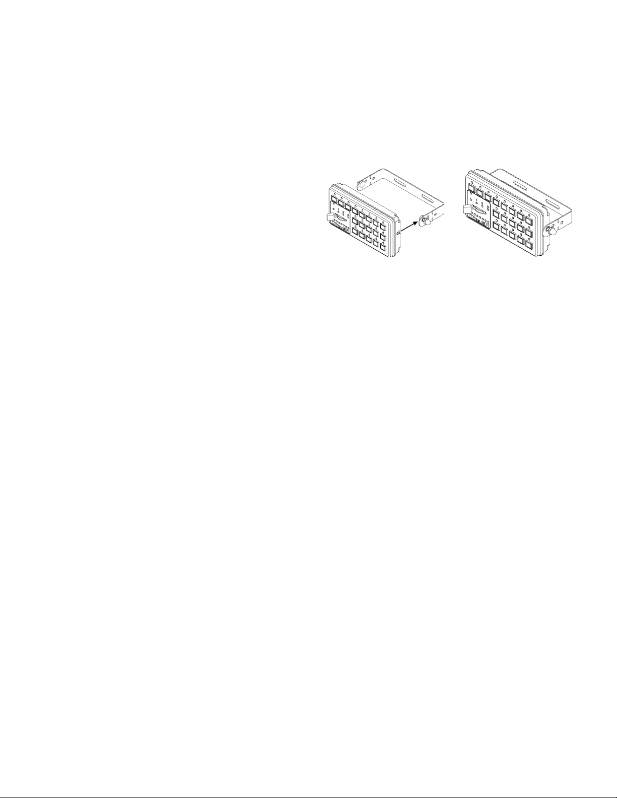
Control Head
The CanTrol™ control head features 18 push-buttons with active
illumination, a 4-position slide switch (off, 1, 2 & 3) and a Traffic Advisor™
display that enables the operator to view a representation of the direction
being displayed. There are two basic mounting brackets for the CanTrol™
control head. One allows the control head to be mounted into your
vehicle’s console (if so equipped). The other allows the control head to be
mounted directly onto the dash or other surface through the use of a bail
strap mounting bracket. Regardless of the style selected, be sure to
observe the air bag warning on the cover of this manual.
Bail-strap mount
1. Position the bail strap in the selected mounting location. Using an awl
or other suitable tool, scribe the surface where the mounting holes
are to be drilled.
Caution: As mounting the control head will require drilling,
it is absolutely necessary to make sure that no other vehicle
components could be damaged in the process. Check both
sides of the mounting surface before starting. If damage is
likely, select a different mounting location.
2. Drill the mounting holes in the areas scribed in step 1. The size of the
drill bit should be determined by the size of the mounting hardware
(#10 sheet metal screw) and thickness of the mounting surface.
3. Using hardware provided (#10 x 3/4” sheet metal screw & #10
internal tooth lockwasher), secure the bail strap to the mounting
location.
Note: There are 3 sets of holes on the bail strap for
positioning the control head at 3 different heights.
4. With the bail strap in place, insert the #10 x 3/8” hex head bolt into
the assembly hole from the inner side of the bail strap. Place the #10
internal-tooth lock washer and the acorn nut on the protruding bolt on
the outer side of the bail strap. Loosely secure the acorn nut to the
hex head bolt.
Bail
Strap
Mount
Now slide the control head onto the bolt heads. Once it is in the position
that the customer has chosen, and the control head has fully engaged the
bolt heads, tighten the acorn nuts until the unit is firmly secured.
A third pair of mounting holes are provided that will enable the control
head to be located much closer to the bail strap than the other pairs allow.
If this closer location is used, the tips of the bail bracket may be broken off
at the notches shown.
Havis Console Mount
The Havis console mounting kit includes all the necessary hardware
needed to secure the control head to the mounting bracket for installation
on a Havis console. The control head mounts onto the console mount
bracket the same way the control head mounts onto the bail bracket as
outlined previously except for the addition of a flat washer that must be
inserted between the control head and the bracket. Please refer to the
manual included with your console for specific information on securing the
control head/mounting bracket assembly onto the console.
For installation into consoles by other manufacturers, a control head
bracket designed for your console must be obtained from the console
manufacturer.
Microphone
A 1/4” port is provided on the CanTrol module for installation of the
microphone.
If the optional 20’ extension cord is used, install this cord as outlined
above. Install the mic plug bracket (included with kit) in the desired area
using #8 x 1/2” hardware (included). Route the cord to the plug bracket,
install the cable end thru the bracket hole and fasten using the hex nut
provided.
Page 4
Page 5
Wiring
WARNING! All customer supplied wires that connect to the positive
terminal of the battery must be sized to supply at least 125% of the
maximum operating current and fused “at the battery” to carry that
load (see wire chart on page 9).
NOTE: Item numbers reference the illustration found on page 8.
IMPORTANT! Wires connecting to the amp/relay module have the
proper terminals pre-installed. If the customer needs to re-terminate
these wires for any reason, the proper tool MUST be used to insure
proper crimping.
System Power (Item 9)
1. Locate the 4-position Molex™ connector (item 9).
2. Using appropriately sized wire, extend the two RED wires to the
Positive (+) battery terminal. Fuse each wire independently @ 40
Amps. DO NOT install these fuses until the wiring for the entire
system has been completed.
3. Using appropriately sized wire, extend the two BLACK wires from the
CanTrol module to the vehicle’s chassis ground. This is typically
adjacent to the battery.
4. Complete the connections and plug the connectors into the CanTrol
module.
Ignition Sense (Item 13)
1. Locate the RED/WHT wire at J17-7.
2. Connect this wire to the vehicle ignition switch. This will allow the
CanTrol system to be turned off with the ignition switch.
Outputs
CanTrol™ offers the following outlets:
16 LED outputs (2.5A Max. each)
3 Aux. outputs (250mA Max each)
Siren Speaker (Item 9)
1. Route the ORG and BRN wires from the CanTrol module to the siren
speaker.
2. Connect ORG wire to the WHT speaker wire (speaker high).
3. Connect BRN wire to BLK speaker wire (speaker low).
NOTE: For dual speaker installation, connect the second speakers wires
to the same destinations as the first speakers wires (see page 10).
Radio Rebroadcast (Item 13)
Two BLU wires (J17-8 & J17-16) are used to connect your two-way radio’s
external speaker for radio rebroadcast. This is an optional connection and
will not effect the other operations.
Note: Radio rebroadcast will NOT work with amplified remote speakers! If
your remote speaker is amplified (i.e.: contains a power amp circuit in the
speaker assembly), do not enable the radio rebroadcast feature.
1. Locate the two wires that connect the external speaker to the twoway radio, cut one of them and splice one of the BLU wires into this
circuit.
2. Cut the remaining speaker wire and splice the remaining BLU wire
into this circuit.
Backlighting (Item 13)
1. Route the BLK/WHT wire (J17-9) from the CanTrol module to the
vehicle’s marker light circuit.
2. Splice this wire into this circuit to enable the control head backlighting
to be active whenever the vehicle’s marker light is active.
Inputs
The CanTrol™ system inputs operate as follows:
Logic Inputs - These are programable inputs and their default
configuration and activation polarity is as follows:
Logic Input 1 (J17-1) - Horn Ring Input (Ground Activated). Identical in
operation to the Manual button when the Horn Transfer Relay has been
activated.
Logic Input 2 (J17-2) - Park Sense 1 (Ground Activated). Terminates siren
operations.
Logic Input 3 (J17-3) - Park Sense 2 (12.8V Activated). Terminates siren
operations.
Inputs 2 & 3 should be connected to the vehicle’s transmission neutral
safety switch signal wire. Always consult your vehicle’s technical
manual before altering your vehicle’s wiring or using this feature.
Wiring modifications may compromise your vehicle’s safety and/or
performance.
Logic Input 4 (J17-4) - Horn Ring Input (12.8V Activated).
Logic Input 5 (J17-9) - Backlight (12.8V Activated). Activates Control Head
backlight.
Logic Input 6 (J17-10) - Sync Lightbar (12.8V Activated). Synchronizes
lightbar pattern with vehicle lighting.
Logic Input 7 (J17-11) - Rear Light Cutout (12.8V Activated). Changes
operation of Master Cutout button from Front Cutout to Rear Cutout.
Logic Input 8 (J17-12) - Hands Free Lighting. Enables Warning Light
pattern changes during Hands Free Siren operation. When enabled,
cycling to Yelp in Hands Free will cause all active vehicle lighting patterns
to change to DoubleFlash 150. Cycling to Piercer will cause all active
vehicle lighting patterns to change to SingleFlash 300. Cycling to Wail
returns all active vehicle lighting patterns to their default pattern.
Analog Inputs - There are three (3) analog inputs (J17-5, J17-13 and
J17-6). Their input voltage may range from 0 to 12VDC. By default, these
inputs are disabled and can be enabled as needed.
The remaining inputs are designated to be used for Ignition Sense (J17-7)
and Radio Repeat (J17-8 & J17-16).
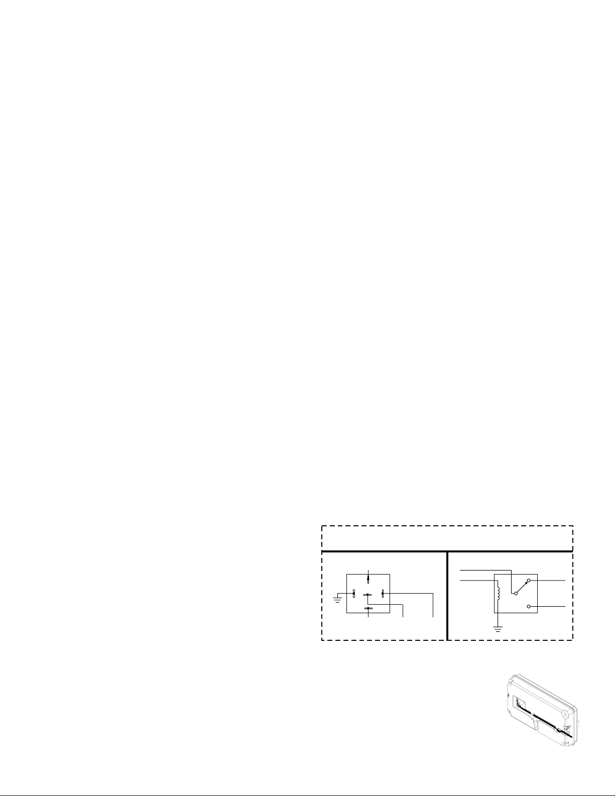
Hands-Free Siren (Items 4 & 13) (Optional)
1. Using a customer supplied relay capable of handling the current of
your vehicle horn, connect as shown below.
Bosch™
Style
(Tyco-P&B P/N:VF4-45F11)
From Vehicle
Horn Relay
30
85 86
87A
87
To
J17-1
Hands-Free Transfer
Relay
To Vehicle
Car HornToJ4-1
Horn Ring
Transfer Relay
(Customer Supplied)
From Vehicle
Horn Relay
To
J4-1
Generic
Style
N.C.
N.O.
To Vehicle
Car Horn
To
J17-1
Control Head Strain Relief
1. Route the control head cable (provided) from
the CanTrol module to the designated
mounting location. Plug this cable securely into
the rear of the control head. Be sure to route
the cable through either of the two recessed
pathways (shown here). This will prevent the
cable from being accidentally disconnected or
pinched by the control head.
Cntrl Head
Cable Strain
Cntrl Hd
Page 5
Page 6

PA Volume Adjustment (Item 11)
Using a small, flat-blade screwdriver, set the potentiometer to its middle
position. With the CanTrol™ system on, activate the PTT (Push To Talk)
feature on the optional microphone. Adjust the potentiometer until a
satisfactory PA volume level is achieved using a normal speaking voice.
Radio Repeat Volume Adjustment (Item 12)
To Adjust the Radio Repeat Levels: Before placing this unit into service,
the Radio Repeat output volume must be adjusted to satisfactory
operating levels. To adjust this level, a small, flat-blade screwdriver is
needed. Locate the Radio Repeat adjustment potentiometer on the left
side of the CanTrol module. Set the volume of the vehicle’s two-way radio
to its normal operating level. Press the RAD button on the control head to
activate Radio Repeat. As incoming transmissions are received, adjust
the Radio Repeat potentiometer to set the desired level. Turn the
potentiometer clockwise to increase the level and counter-clockwise to
decrease the level.
Default Control Head Configuration:
There is an almost limitless number of configurations in which the CanTrol
system can be programmed. Each of the available control heads operate
differently from one another. This section will outline the default
configurations for each control head.
Standard Control Head
The following defines the default
operation of the standard CanTrol
Control Head.
#1 (Stand-by) - This button clears all
siren operations and forces the siren
off.
#2 (Radio Repeat) - This button will rebroadcast your radio output
through the siren speaker.
1 2 3 4
123
5
6
7
8
9
10
11
12
13
14
15
16
17
18
Siren Inactive Tone - This is the tone that will be generated when
the MAN button is pressed while no other tone is active. Ramp Stop
is the default.
T3 Override Tone - This is the tone that will override T3 when the
MAN button is pressed. Airhorn is the default
NOTE: Yelp always overrides the Wail tone, T3 always overrides the
Yelp tone and the T3 Override tone selected in the previous
paragraph overrides the T3 tone.
#8 (Airhorn) - This button will broadcast the Airhorn tone as long as the
button is pressed, over-riding other siren tones.
#9 - This button is not used
#10 (Cruise) - This button activates lightbar cruise lights.
#11 (Master Cut) - Activates Front Light Cutout by default. If Logic Input 7
(J17-11) is active, Rear Light Cutout will be activated instead.
#12 (AUX 3) - Activates high current output 6 (J1-6).
#13 (Low Power) - Activates Low Power on all active warning lights
except lightbar corner modules.
#14 (Takedown) - Activates lightbar Takedown and/or worklights if
present.
#15 (Left Alley) - Activates lightbar Left Alley if present.
#16 (Right Alley) - Activates lightbar Right Alley if present.
#17 - This button is not used.
#18 - This button is not used.
#3 (Hands-Free) - This button will put the siren into Hands-Free mode.
This is similar to the stand-by mode except that the Horn Ring (or MAN
button) can activate the siren and then cycle through the H/F buffer. To
deactivate the siren, press STBY.
#4 (Wail) - This button will broadcast the Wail tone. The tone can be
silenced by pressing the WAIL button a second time or by pressing the
STBY button.
#5 (Yelp) - This button will broadcast the Yelp tone. The tone can be
silenced by pressing the YELP button a second time or by pressing the
STBY button.
#6 (Piercer) - This button will broadcast the Piercer tone. The tone can be
silenced by pressing the PIER button a second time or by pressing the
STBY button.
#7 (Manual) - This button has several functions. If the siren is inactive, the
Manual button starts the "Siren Inactive Tone." If Wail, Yelp or T3 are
active, then Manual can initiate the "Override mode." In Hands-Free
mode, the Manual button can toggle through the buffered HF tones:
Cycle Hands-free - Pressing the MAN button while the system is in
Hands-Free mode will generate a WAIL tone. A second press will
change that tone to YELP. A third press will change that tone to T3. A
subsequent press will cause the cycle to repeat beginning with WAIL.
Slide Switch Position 0 - Shuts off siren and primary lighting.
Slide Switch Position 1 - Activates all rear warning lights. All vehicle
warning lights will flash in Synchronous SignalAlert™ 75 (Alternating). The
lightbar will also flash in Alternating SignalAlert 75, but asynchronously. To
force the lightbar to flash synchronously, activate Logic Input 6 (J17-10).
Slide Switch Position 2 - Activates both front and rear warning lights. All
vehicle warning lights will flash in Synchronous SignalAlert 75
(Alternating). The lightbar will also flash in Alternating SignalAlert 75, but
asynchronously. To force the lightbar to flash synchronously, activate
Logic Input 6 (J17-10).
Slide Switch Position 3 - Activates all warning lights including wig-wigs,
flashing Alleys and Takedowns. All vehicle lights will flash in Synchronous
SignalAlert 75 (Alternating). The lightbar will also flash in Alternating
SignalAlert 75, but Asynchronously. To force the lightbar to flash
synchronously, activate Logic Input 6 (J17-10).
Page 6
Page 7
Control Head with Priority Button
This model operates the same as the standard control head except that
the slide switch has been replaced with the Master Emergency Button.
This button activates all warning lights including wig-wigs, flashing Alleys
and Takedowns. All vehicle lights will flash in Synchronous SignalAlert 75
(Alternating). The lightbar will also flash in Alternating SignalAlert 75, but
Asynchronously. To force the lightbar to flash synchronously, activate
Logic Input 6 (J17-10).
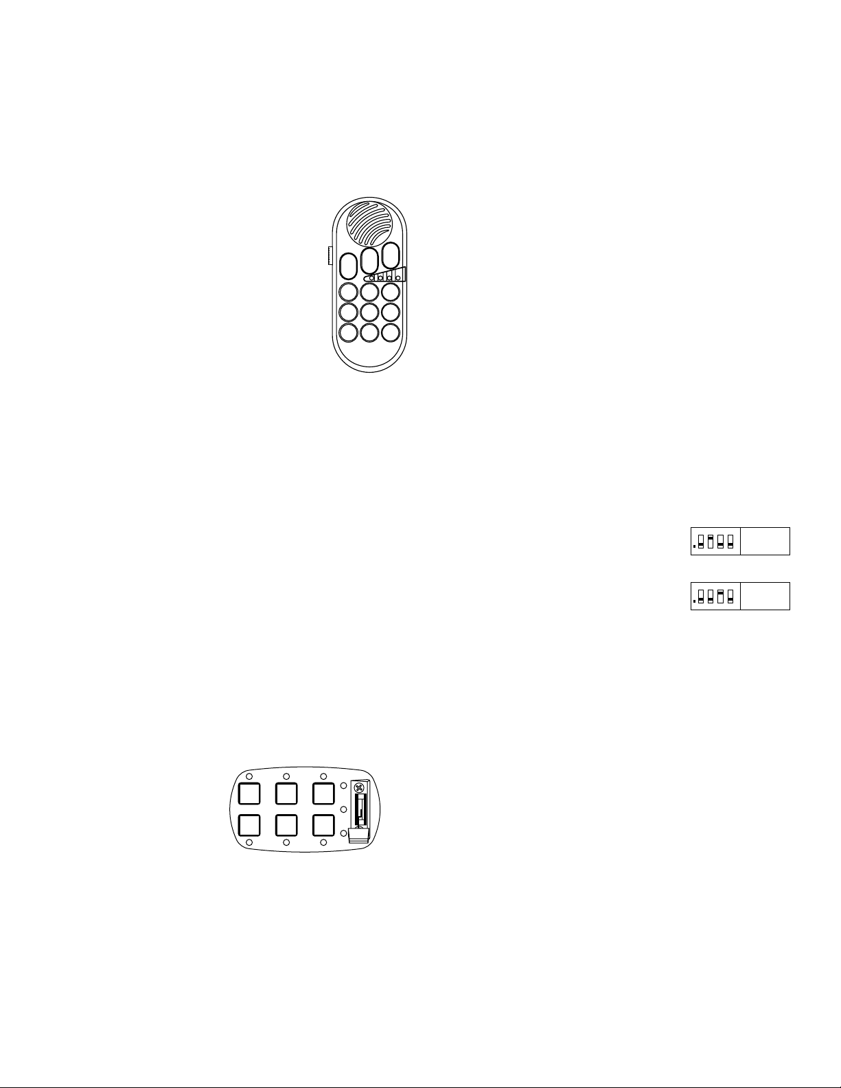
Hand-held Control Head
Priority Button 1 - Activates all rear warning lights. All
vehicle warning lights will flash in Synchronous Signal
Alert 75 (Alternating). The lightbar will also flash in
Alternating Signal Alert 75, but Asynchronously. To
force the lightbar to flash synchronously, activate Logic
Input 6 (J17-10).
Priority Button 2 - Activates both front and rear
warning lights. All vehicle warning lights will flash in
Synchronous Signal Alert 75 (Alternating). The lightbar
will also flash in Alternating Signal Alert 75, but
Asynchronously. To force the lightbar to flash
synchronously, activate Logic Input 6 (J17-10).
Priority Button 3 - Activates all warning lights including wig-wigs, flashing
Alleys and Takedowns. All vehicle lights will flash in Synchronous
SignalAlert 75 (Alternating). The lightbar will also flash in Alternating
SignalAlert 75, but Asynchronously. To force the lightbar to flash
synchronously, activate Logic Input 6 (J17-10).
#1 (Hands Free) - Enables Hands Free operation.
#2 (Manual) - Activates Manual Stop siren tone, cycles Hands Free
operation and toggles the siren override tone for Wail, Yelp and Piercer.
#3 (Air Horn) - Activates Air Horn tone.
#4 (Wail) - Activates Wail siren tone.
#5 (Radio) - Activates Radio Rebroadcast.
#6 (Alleys) - Activates Lightbar Alley Lights. First press is for Left Alley,
second press is for Right Alley and the third press is for both Alleys.
#7 - This button is not used.
P1
P3
P2
1
2
3
4
7
6
5
8
9
Slide Switch 2 - Activates both front and rear warning lights. All vehicle
warning lights will flash in Synchronous Signal Alert 75 (Alternating). The
lightbar will also flash in Alternating Signal Alert 75, but Asynchronously.
To force the lightbar to flash synchronously, activate Logic Input 6 (J17-
10).
Slide Switch 3 - Activates all warning lights including wig-wigs, flashing
Alleys and Takedowns. All vehicle lights will flash in Synchronous
SignalAlert 75 (Alternating). The lightbar will also flash in Alternating
SignalAlert 75, but Asynchronously. To force the lightbar to flash
synchronously, activate Logic Input 6 (J17-10).
#1 (Hands Free) - Enables Hands Free operation.
#2 (Manual) - Activates Manual Stop siren tone, cycles Hands Free
operation and toggles the siren override tone for Wail, Yelp and Piercer.
#3 (Air Horn) - Activates Air Horn tone.
#4 - This button is not used.
#5 - Activates the Takedowns and Alley lights as follows:
First press activates Takedowns
Second press activates Left Alley
Third press activates Right Alley
Fourth press activates Takedowns and Alley lights
Fifth press is Off.
#6 - This button is not used.
Dip Switch 1 - This dip switch is not used.
Dip Switch 2 (Cruise w/Backlight) - Enables
Cruise light activation when backlight is active.
Dip Switch 3 (All Bar Patterns) - Replaces
Asynchronous SignalAlert with an All Bar pattern
on slide switch 1, 2 and 3.
Dip Switch 4 - This dip switch is not used..
1ON234
1ON234
On Off
2 1,3,4
On Off
3 1,2,4
#8 - This button is not used.
#9 (Takedown) - Activates lightbar takedowns or work lights, if present.
Six-button Control Head
Slide Switch 1 - Activates all rear
warning lights. All vehicle warning
lights will flash in Synchronous
Signal Alert 75 (Alternating). The
lightbar will also flash in
Alternating Signal Alert 75, but
Asynchronously. To force the
lightbar to flash synchronously,
activate Logic Input 6 (J17-10).
1
4
3
2
5
6
Pos.3
Pos.2
Pos.1
Pos.0
Page 7
Page 8
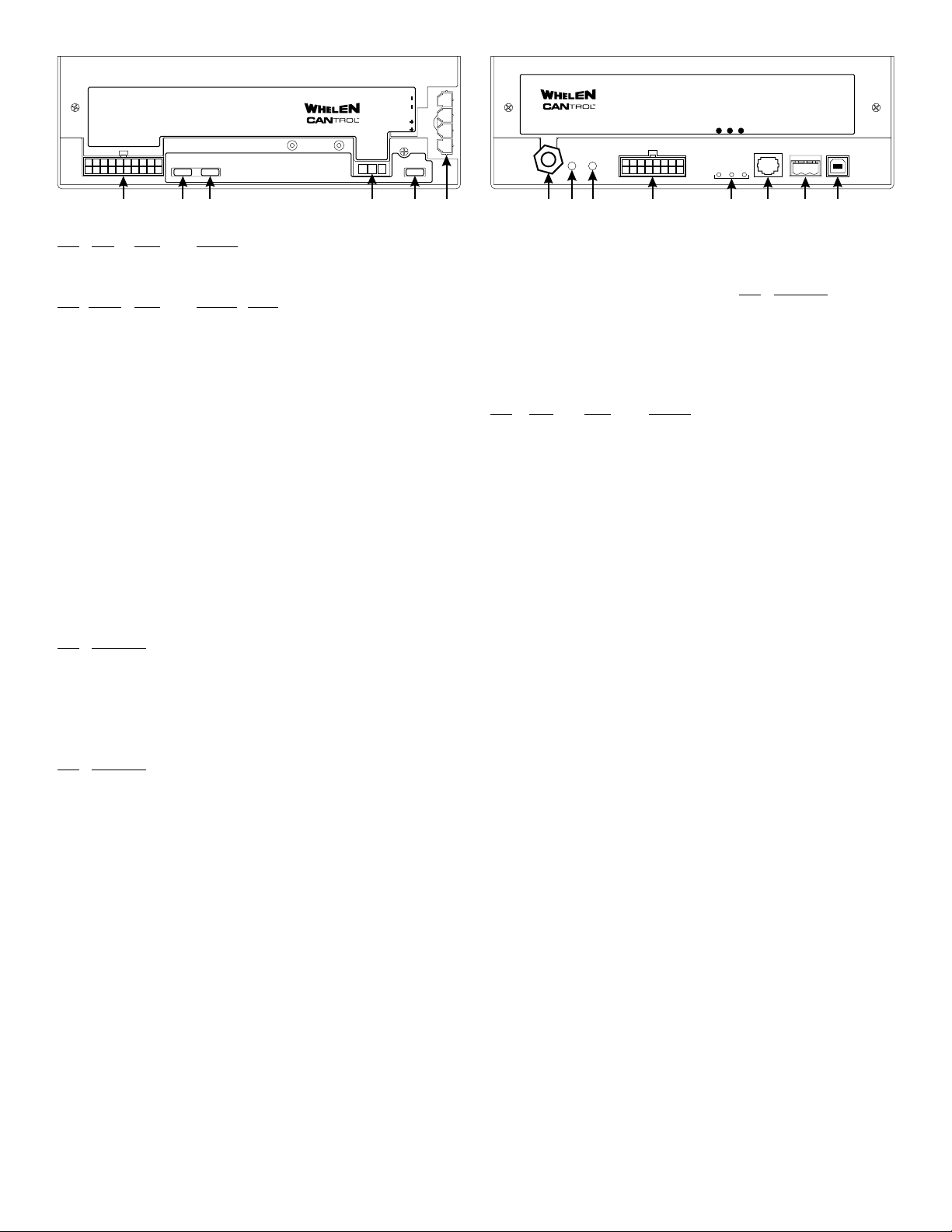
LED OUTPUTS J4 (1-16)
LC AUX 1,2,3
10
9
20
171819 16
®
LOGIC INPUTS J17
53241
678
USB
123
PROGRAM
PORT
CTRL
ERR WC POW
HEADWCLIGHTBAR
10111213141516
9
POWER
SIREN
FUSE
1
2
3
PA MIC RAD
4
®
MAIN
SIREN
53241678
LEDS1LEDS
1112131415
2
20 20 20
SPEAKERS
123
123 456
1 (J4) - LED Outputs 1-16 & LC AUX 1, 2, 3
Pos. AUX Color Function
J4-1 1 WHT/BLK Transfer Relay
J4-2 2 RED/WHT Wig Wag
J4-11 3 WHT Siren Activated Camera Icon
Pos. Output Color Location Phase
J4-3 1 BRN Front 1
J4-4 2 RED Front 1
J4-5 3 ORG Front 1
J4-6 4 YEL Front 1
J4-7 5 WHT/BRN Front 2
J4-8 6 WHT/RED Front 2
J4-9 7 WHT/ORG Front 2
J4-10 8 WHT/YEL Front 2
J4-12
- Not Used -
J4-13 25 GRN Rear 1
J4-14 26 BLU Rear 1
J4-15 27 VIO Rear 1
J4-16 28 GRY Rear 1
J4-17 29 WHT/GRN Rear 2
J4-18 30 WHT/BLU Rear 2
J4-19 31 WHT/VIO Rear 2
J4-20 32 WHT/GRY Rear 2
2 - LEDS1
This fuse (20 Amp) protects
Outputs 1 thru 8.
3 - LEDS2
This fuse (20 Amp) protects
Outputs 9 thru 16.
4 - Siren Speaker
Pos. Description
1 Speaker (+)
2 Not Used
3 Speaker (-)
5 - Siren Fuse
This fuse (20 Amp) Protects the
Siren Output.
6 - Main Power
Pos. Description
1 Ground
2 Ground
3 +12VDC (Fuse@40A)
4 +12VDC (Fuse@40A)
7 - PA Microphone Port
This port accepts a standard 1/4" Microphone
plug for PA functions. NOTE: If your system
uses the hand-held controller, this port should
not be used.
8 - MIC Volume Adjustment
Used to set the PA broadcast level to the
desired volume (see text).
9 - RAD Repeat Volume
Used to set the Radio Repeat broadcast level
to the desired volume (see text).
10 (J17) - Logic Inputs
Pos. Input Color Function
J17-1 Logic 1 WHT/BRN Horn Sense (Neg.)
J17-2 Logic 2 WHT/RED Park Sense 1 (Neg.)
J17-3 Logic 3 WHT/ORG Park Sense 2 (Pos.)
J17-4 Logic 4 WHT/YEL Horn Sense (Pos.)
J17-9 Logic 5 BLK/WHT Backlight
J17-10 Logic 6 WHT/GRN SYNC Lightbar
J17-11 Logic 7 WHT Rear Cut
J17-12 Logic 8 WHT/BLU HF Lighting
J17-5 Analog 1 WHT/BLK Unused
J17-13 Analog 2 WHT/GRY Unused
J17-6 Analog 3 WHT/VIO Unused
J17-7 Ign.Sense RED/WHT Ignition
J17-8 Radio BLU Radio Repeat
J17-16 Radio BLU Radio Repeat
11 - Diagnostic LEDs
ERR (Error) LED
Steady CanTrol™ Controller Bus is set to
Off No Error.
Single Flash Bad CanTrol™ connection. Check
Double Flash Error Control Event. Check
WC (CanTrol™ Serial Data Bus) LED
Steady Good communication received
Off Check Power LED;
Fast Blink Pre-operational State (Boot-up).
Single Flash Bad connection or
POW (Power) Status LED
Steady system is On.
Off system is Off.
OFF. Check Interface Box.
Lightbar I/O or Interface Box for
proper operation.
Lightbar I/O.
from Lightbar.
If Off, turn on Controller.
If On, check connections
CanTrol™
CanTrol™
or Interface Box for proper
operation.
CanTrol™
CanTrol™
off. Check lightbar I/O
CanTrol ID
1210789 11 1314
12 - Control Head
Used to connect the control
head to the CanTrol™ system.
13 - WC Lightbar
Pos. Description
1 CAN A
2
Not Used
3 CAN B
14 - USB Program Port
Used to program the CanTrol™
system using a Windows™
based laptop.
Page 8
Page 9
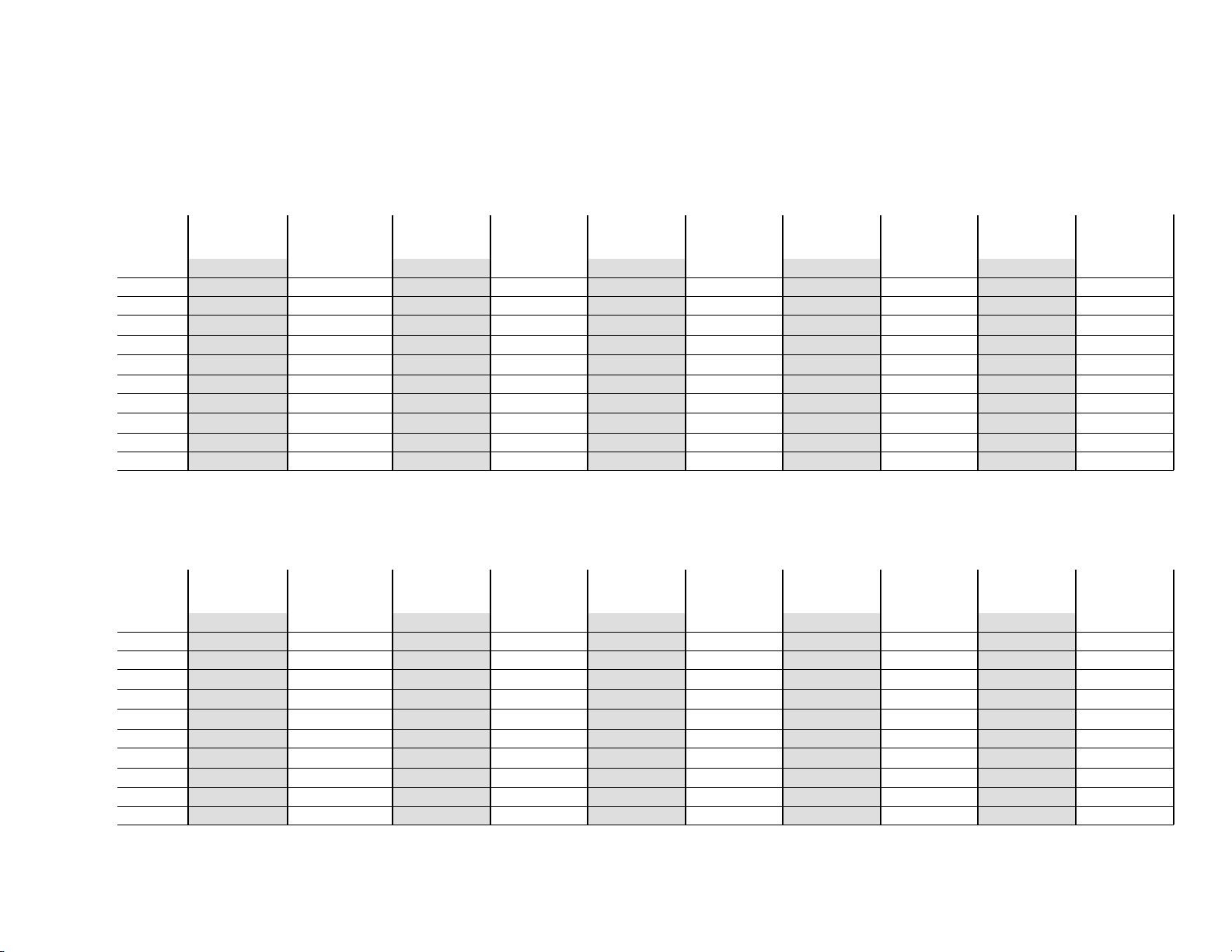
Wire Gauge Calculation Chart
Maximum Current Draw Through The Wire
5 Amps
22 AWG
20 AWG
18 AWG
16 AWG
14 AWG
12 AWG
10 AWG
8AWG
6AWG
Wire Gauge
Page 9
4AWG
2AWG
6 Feet 3 Feet Insufficient Insufficient Insufficient Insufficient Insufficient Insufficient Insufficient Insufficient
9.5 Feet 5 Feet 3 Feet Insufficient Insufficient Insufficient Insufficient Insufficient Insufficient Insufficient
15 Feet 7.5 Feet 5 Feet 4 Feet 3 Feet Insufficient Insufficient Insufficient Insufficient Insufficient
24.5 Feet 12 Feet 8 Feet 6 Feet 5 Feet 4 Feet 3.5 Feet 3 Feet Insufficient Insufficient
39 Feet 19.5 Feet 13 Feet 9.5 Feet 8 Feet 6.5 Feet 5.5 Feet 5 Feet 4.5 Feet 4 Feet
62 Feet 31 Feet 20.5 Feet 15.5 Feet 12.5 Feet 10.5 Feet 9 Feet 7.5 Feet 7 Feet 6 Feet
98 Feet 49 Feet 32.5 Feet 24.5 Feet 19.5 Feet 16.5 Feet 14 Feet 12.5 Feet 11 Feet 10 Feet
156 Feet 78 Feet 52 Feet 39 Feet 31 Feet 26 Feet 22.5 Feet 19.5 Feet 17.5 Feet 15.5 Feet
248.5 Feet 124 Feet 82.5 Feet 62 Feet 49.5 Feet 41.5 Feet 35.5 Feet 31 Feet 27.5 Feet 25 Feet
395 Feet 197.5 Feet 131 Feet 98.5 Feet 79 Feet 66 Feet 56.5 Feet 49.5 Feet 44 Feet 39.5 Feet
629 Feet 314 Feet 209 Feet 157 Feet 125.5 Feet 104.5 Feet 89.5 Feet 78.5 Feet 69.5 Feet 63 Feet
10 Amps
15 Amps
Wire Gauge Chart
20 Amps
25 Amps
30 Amps
35 Amps
40 Amps
45 Amps
50 Amps
Maximum Current Draw Through The Wire
22 AWG
20 AWG
18 AWG
16 AWG
14 AWG
12 AWG
10 AWG
8AWG
6AWG
Wire Gauge
4AWG
2AWG
55 Amps
Insufficient Insufficient Insufficient Insufficient Insufficient Insufficient Insufficient Insufficient Insufficient Insufficient
Insufficient Insufficient Insufficient Insufficient Insufficient Insufficient Insufficient Insufficient Insufficient Insufficient
Insufficient Insufficient Insufficient Insufficient Insufficient Insufficient Insufficient Insufficient Insufficient Insufficient
Insufficient Insufficient Insufficient Insufficient Insufficient Insufficient Insufficient Insufficient Insufficient Insufficient
3.5 Feet 3 Feet 3 Feet 3 Feet Insufficient Insufficient Insufficient Insufficient Insufficient Insufficient
5.5 Feet 5 Feet 5 Feet 4.5 Feet 4 Feet 4 Feet 3.5 Feet 3.5 Feet 3.5 Feet 3 Feet
9 Feet 8 Feet 7.5 Feet 7 Feet 6.5 Feet 6 Feet 6 Feet 5.5 Feet 5 Feet 5 Feet
14 Feet 13 Feet 12 Feet 11 Feet 10.5 Feet 10 Feet 9 Feet 8.5 Feet 8 Feet 8 Feet
22.5 Feet 20.5 Feet 19 Feet 17.5 Feet 16.5 Feet 15.5 Feet 14.5 Feet 14 Feet 13 Feet 12.5 Feet
36 Feet 33 Feet 30.5 Feet 28 Feet 26.5 Feet 24.5 Feet 23 Feet 22 Feet 21 Feet 19.5 Feet
57 Feet 52.5 Feet 48.5 Feet 45 Feet 42 Feet 39 Feet 37 Feet 35 Feet 33 Feet 31.5 Feet
60 Amps
65 Amps
70 Amps
75 Amps
80 Amps
85 Amps
90 Amps
95 Amps
100 Amps
Page 10
Page 10
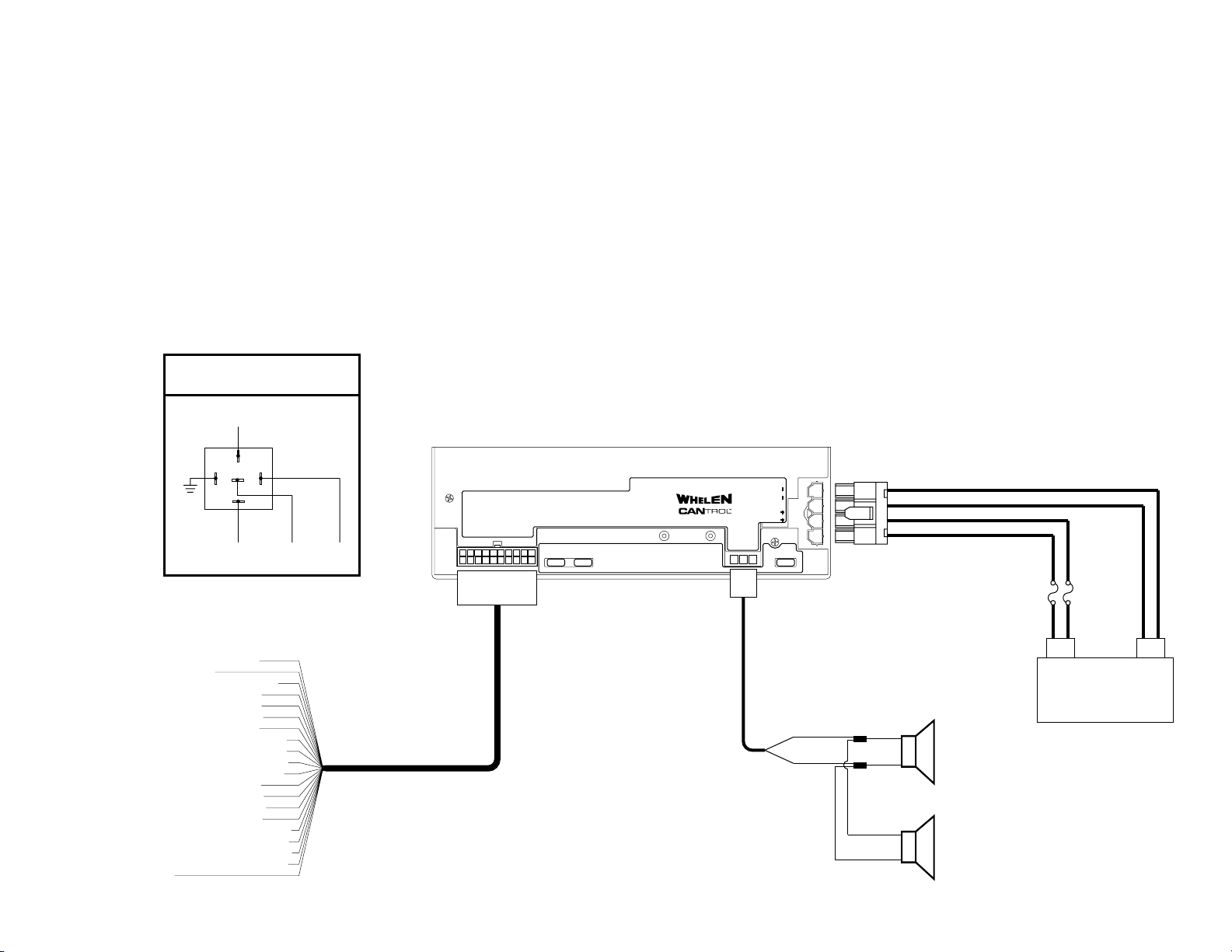
CanTrol™ System Wiring Guide - 1
Horn Ring Transfer Relay
TYCO-P&B P/N: VF4-45F11
(Not Included)
System Wiring Guide 1
From Vehicle
Horn Relay
30
85 86
87A
87
LED OUTPUTS J4 (1-16)
LC AUX 1,2,3
To
J17-1
To Vehicle
Car Horn
To
J4-1
10
53241678
9
20
171819 16
LEDS1LEDS
1112131415
2
20 20 20
®
SIREN
SPEAKERS
1
POWER
2
3
MAIN
4
SIREN
FUSE
123
J-1.4 Horn Transfer Relay - WHT/BLK
J4- 2. Wig-Wag - RED/WHT
J4-11. Camera Icon (Siren Activated) - WHT
J4- 3. Output 1 - BRN - Front - Phase 1
J4- 4. Output 2 - RED - Front - Phase 1
J4- 5. Output 3 - ORG - Front - Phase 1
J4- 6. Output 4 - YEL - Front - Phase 1
J4- 7. Output 5 - WHT/BRN - Front - Phase 2
J - . - - Phase4 8 Output 6 WHT/RED - Front 2
J4- 9. Output 7 - WHT/ORG - Front - Phase 2
J4-10. Output 8 - WHT/YEL - Front - Phase 2
J4-13. Output 9 - GRN - Rear - Phase 1
J4-14. Output 10 - BLU - Rear - Phase 1
J4-15. Output 11 - ORG - Rear - Phase 1
J4-16. Output 12 - YEL - Rear - Phase 1
J4-17. Output 13 - WHT/GRN - Rear - Phase 2
J4-18. Output 14 - WHT/BLU - Rear - Phase 2
J4-19. Output 15 - WHT/ORG - Rear - Phase 2
J4-20. Output 16 - WHT/YEL - Rear - Phase 2
J2-12. NOT USED
ORANGE
(High)
BROWN
(Low)
WHT
BLK
WHT
BLK
Speaker 1
(optional)
Speaker 2
(+)
Battery
(-)
Page 11
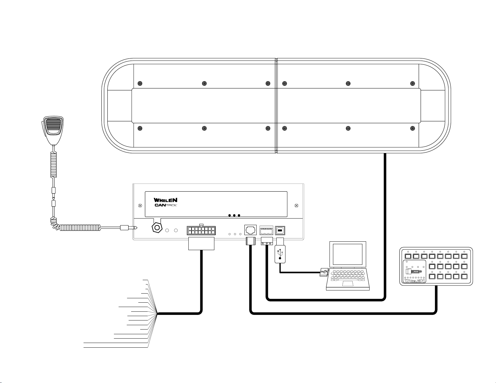
CanTrol™ System Wiring Guide - 2
System Wiring Guide 2
Microphone Not For Use
With The CanTrol™
Hand-Held Controller
Justice WC Lightbar
Shown For Reference
Page 11
®
USB
Optional Microphone Extension
Cord Shown For Reference Only
PA MIC RAD
LOGIC INPUTS J17
ERR WC POW
CTRL
HEADWCLIGHTBAR
PROGRAM
PORT
J-1. - -17 Logic Input 1 WHT/BRN Horn Sense (Neg.)
J17- 2. Logic Input 2 - WHT/RED - Park Sense 1 (Neg.)
J17- 3. Logic Input 3 - WHT/ORN - Park Sense 2 (Pos.)
J17- 4. Logic Input 4 - WHT/YEL - Horn Sense (Pos.)
J17- 9. Logic Input 5 - BLK/WHT - Backlight
J17-10. Logic Input 6 - WHT/GRN - SYNC Lightbar
J17-11. Logic Input 7 - WHT - Rear Cut
J17-12. Logic Input 8 - WHT/BLU - HF Lighting
J-. -17 5 Analog Input 1 WHT/BLK - Unused
J17-13. Analog Input 2 - WHT/GRY - Unused
J17- 6. Analog Input 3 - WHT/VIO - Unused
J17- 7. Ignition Sense - RED/WHT - Vehicle Ignition
J17- 8. Radio - BLU - Radio Repeat
J17-16. Radio - BLU - Radio Repeat
J17-14. Not Used
J17-15. Not Used
53241
678
10111213141516
9
123
USB
Standard CanTrol™ Control
Head Shown For Reference
123
Page 12
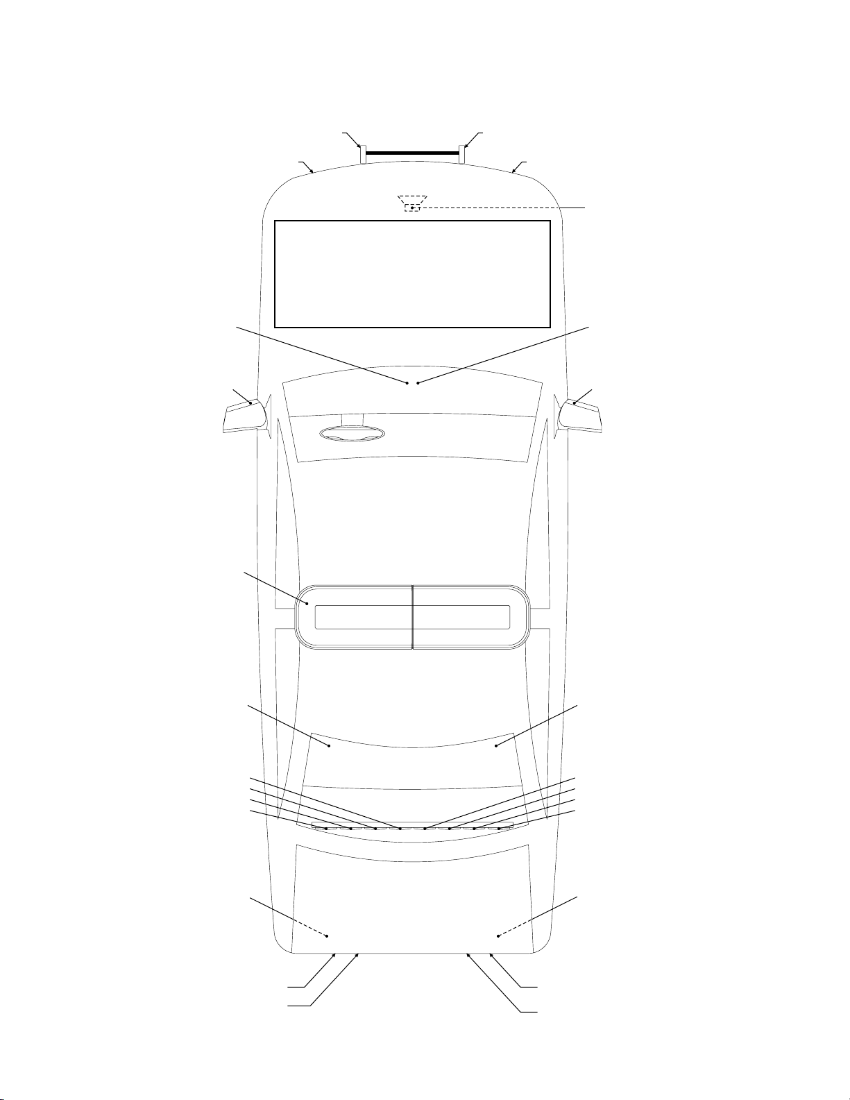
Sample CanTrol™ System
J4-3 (#1) BRN - Driver Push Bar (Blue)
Sample ConTrol Sys
J4-4 (#2) RED - Driver Headlight Vertex (White)
J4-6 (#4) YEL - Driver Dashboard (Red)
J4-5 (#3) ORG - Driver Mirror-Beam (Red)
J4-7 (#5) WHT/BRN - Pass. Push Bar (Red)
J4-8 (#6) WHT/RED - Pass. Headlight Vertex (White)
This illustration presents one example of a possible
configuration. T assignments, as well as
head operations can easily be redefined using the CanTrol
software
limitless number of custom configurations based on your
specific equipment.
Refer to the online help and video tutorials, accessible from
the CanTrol software, for further information.
he default wire control
,
. This flexibility makes it possible to design an almost
J17-8 BLU - Radio Repeat
J17-16 BLU - Radio Repeat
J4-10 (#8) WHT/YEL - Pass. Dashboard (Blue)
J4-9 (#7) WHT/ORG - Pass. Mirror-Beam (Blue)
WC Lightbar
J4-13 (#25) GRN - Driver Rear Deck (Red)
J10-4 YEL - T A 4raffic dvisor (module # )
J10-3 ORG - Traffic Advisor (module #3)
J10-2 RED - Traffic Advisor (module #2)
J10-1 BRN - Traffic Advisor (module #1)
J4-14 (#26) BLU - Driver Trunk Lid (Red)
J4-17 (#29) WHT/GRN - Pass. Rear Deck (Blue)
J10-5 GRN - 5Traffic Advisor (module # )
J10-6 BLU - Traffic Advisor (module #6)
J10-7 VIO - Traffic Advisor (module #7)
J10-8 GRY - Traffic Advisor (module #8)
J4-18 (#30) WHT/BLU - Pass. Trunk Lid (Blue)
J4-15 (#27) VIO - Driver Tail Vertex (Red)
J4-16 (#28) GRY - Driver Reverse Vertex (White)
J4-19 (#31) WHT/VIO - Pass. Tail Vertex (Red)
J4-20 (#32) WHT/GRY - Pass. Reverse Vertex (White)
Page 12
Page 13
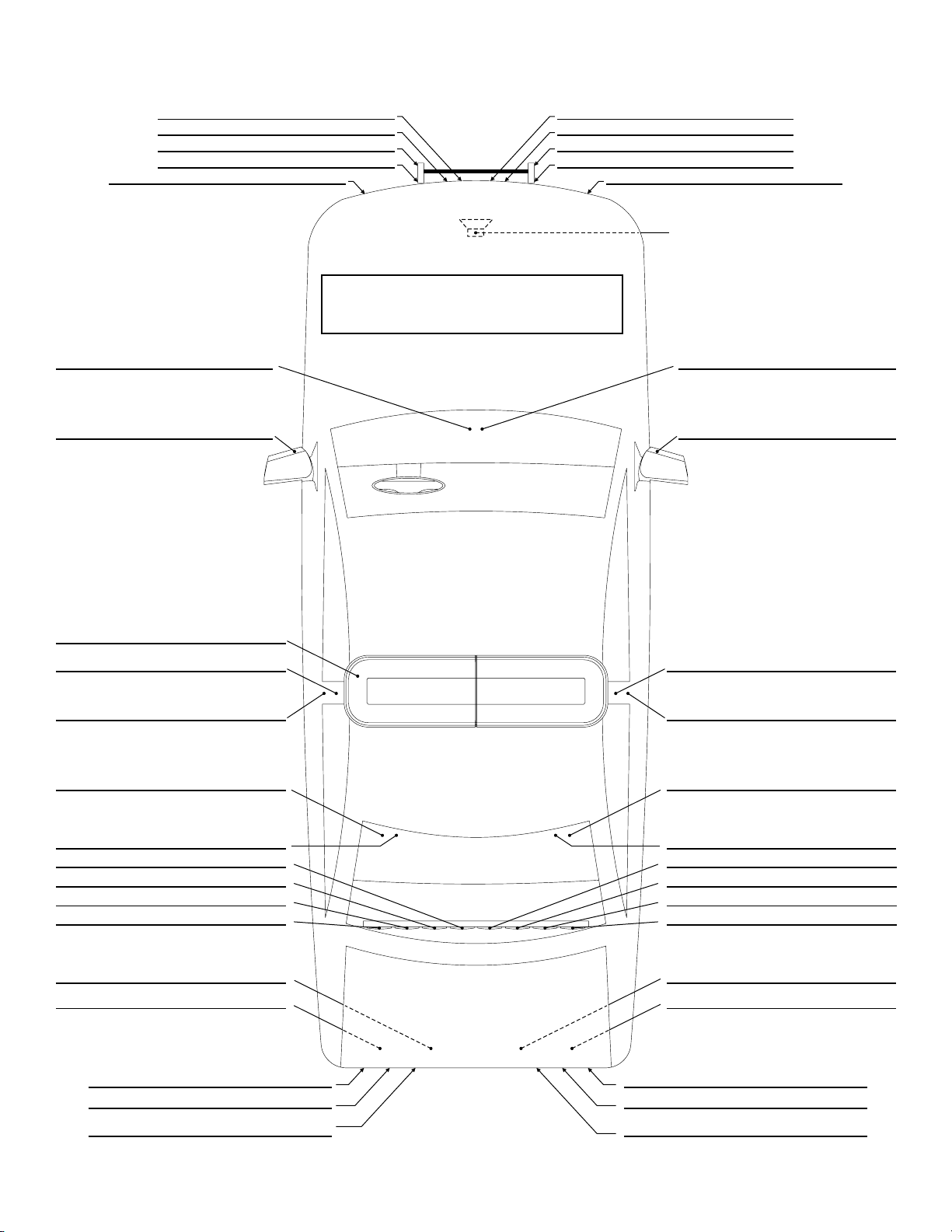
CanTrol™ System Worksheet
CanTrol Sys Wrksht
This worksheet is provided to allow the installer to provide a
visual record of what specific vehicle equipment is activated
and/or controlled with specific inputs or outputs to the
customer.
J17-8 BLU - Radio Repeat
J17-16 BLU - Radio Repeat
Page 13
Page 14
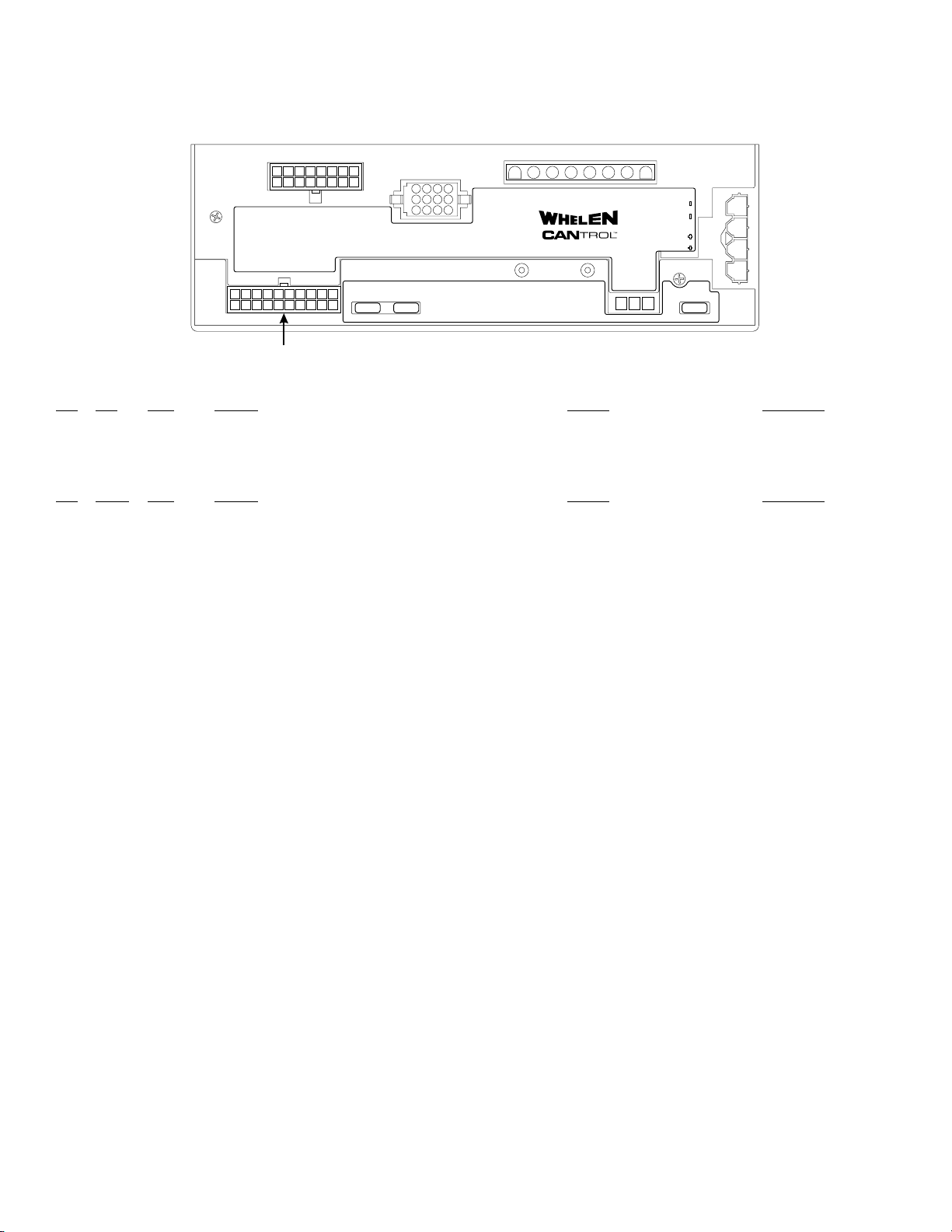
C
anTrol™Installation Worksheet
(J-4)
CanTrol Inst.Wrksht J-
4
10
20
10
11 1 21314
9
LED OUTPUTS J2 (17-32)
LED OUTPUTS J4 (1-16)
LC AUX 1,2,3
53241678
9
171819 16
15 16
53241
678
LEDS1LEDS
1112131415
20 20 20
10
7
14
11
5
8
2
12
9
36
TRAFFIC ADVISOR J10
2
4
218
3
5
HIGH CURRENT OUTPUTS J1
6
®
SPEAKERS
7
SIREN
1
MAIN
POWER
2
3
4
SIREN
FUSE
123
J4
J4 - Outputs 1-16 + LC AUX 1, 2 & 3
AUX Color Function Location Activated By
Pos.
J4-1 1 WHT/BLK __________________________________________________________ _____________________________ ______________________
J4-2 2 RED/WHT
J4-11 3 WHT
Pos. Output Color Function Location Activated By
J4-3 1 BRN __________________________________________________________ _____________________________ ______________________
J4-4 2 RED __________________________________________________________ _____________________________ ______________________
J4-5 3 ORG __________________________________________________________ _____________________________ ______________________
J4-6 4 YEL __________________________________________________________ _____________________________ ______________________
J4-7 5 WHT/BRN
J4-8 6 WHT/RED
J4-9 7 WHT/ORG
J4-10 8 WHT/YEL
J4-12
J4-13 9 GRN __________________________________________________________ _____________________________ ______________________
J4-14 10 BLU __________________________________________________________ _____________________________ ______________________
J4-15 11 VIO __________________________________________________________ _____________________________ ______________________
J4-16 12 GRY __________________________________________________________ _____________________________ ______________________
J4-17 13 WHT/GRN __________________________________________________________ _____________________________ ______________________
J4-18 14 WHT/BLU __________________________________________________________ _____________________________ ______________________
J4-19 15 WHT/VIO __________________________________________________________ _____________________________ ______________________
J4-20 16 WHT/GRY __________________________________________________________ _____________________________ ______________________
- Not Used -
__________________________________________________________ _____________________________ ______________________
__________________________________________________________ _____________________________ ______________________
__________________________________________________________ _____________________________ ______________________
__________________________________________________________ _____________________________ ______________________
__________________________________________________________ _____________________________ ______________________
__________________________________________________________ _____________________________ ______________________
This worksheet has been provided so that a written record of all Input, Output and Axillary
connections may be created. After all pertinent installation data has been verified and
recorded, store and retain this sheet forfuture reference.
Page 14
Page 15
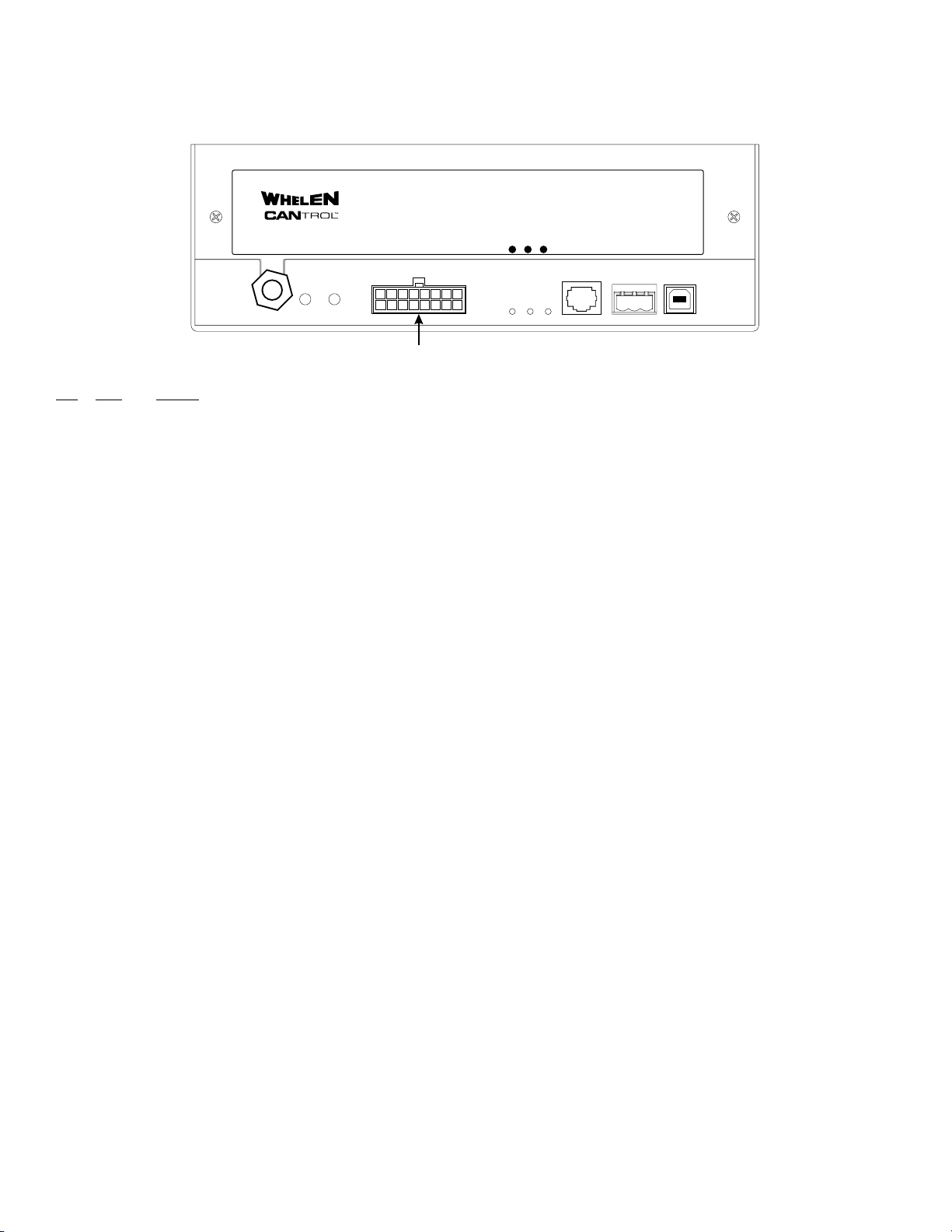
C
anTrol™Installation Worksheet
CanTrol Wrksht J17
(J-17)
®
PA MIC RAD
LOGIC INPUTS J17
53241
678
10111213141516
ERR WC POW
9
CTRL
HEADWCLIGHTBAR
123
USB
PROGRAM
PORT
J-17
J17 - Logic Inputs
Color Function
Pos.
J17-1 WHT/BRN _________________________________________________________________________________________________________________________________
J17-2 RED
WHT/ _________________________________________________________________________________________________________________________________
J17-3 ORG
WHT/ _________________________________________________________________________________________________________________________________
J17-4 YEL
WHT/ _________________________________________________________________________________________________________________________________
J17-5 WHT/BLK _________________________________________________________________________________________________________________________________
J17-6 WHT/VIO _________________________________________________________________________________________________________________________________
J17-7 RED/WHT Ignition (Pre-assigned and non-programmable)
J17-8 BLU Radio Repeat (Pre-assigned and non-programmable)
J17-9 BLK/WHT Backlight (Pre-assigned and non-programmable)
J17-10 WHT/GRN _________________________________________________________________________________________________________________________________
J17-11 WHT _________________________________________________________________________________________________________________________________
J17-12 WHT/BLU _________________________________________________________________________________________________________________________________
J17-13 WHT/GRY _________________________________________________________________________________________________________________________________
J17-14 (non-programmable)
- Not Used -
J17-15 (non-programmable)
- Not Used -
J17-16 BLU Radio Repeat (Pre-assigned and non-programmable)
This worksheet has been provided so that a written record of all Input, Output and Axillary
connections may be created. After all pertinent installation data has been verified and
recorded, store and retain this sheet forfuture reference.
Page 15
 Loading...