

Page 1

®
ENGINEERING COMPANY INC.
51 Winthrop Road
Chester, Connecticut 06412-0684
Phone: (860) 526-9504
WeCan™ REMOTE16
Wiring Guide:
Expansion Module
Fax: (860) 526-4078
Internet: www.whelen.com
Sales e-mail: autosale@whelen.com
Canadian Sales e-mail: canadiansales@whelen.com
Customer Service e-mail: custserv@whelen.com
Safety First
This document provides all the necessary information to allow your Whelen product to be properly and safely installed.
Before beginning the installation and/or operation of your new product, the installation technician and operator must
read this manual completely. Important information is contained herein that could prevent serious injury or damage.
• Proper installation of this product requires the installer to have a good understanding of automotive
electronics, systems and procedures.
• Failure to use specified installation parts and/or hardware will void the product warranty!
• If mounting this product requires drilling holes, the installer MUST be sure that no vehicle components or
other vital parts could be damaged by the drilling process. Check both sides of the mounting surface
before drilling begins. Also de-burr any holes and remove any metal shards or remnants. Install grommets
into all wire passage holes.
• If this manual states that this product may be mounted with suction cups, magnets, tape or Velcro®, clean the
mounting surface with a 50/50 mix of isopropyl alcohol and water and dry thoroughly.
• Do not install this product or route any wires in the deployment area of your air bag. Equipment mounted
or located in the air bag deployment area will damage or reduce the effectiveness of the air bag, or
become a projectile that could cause serious personal injury or death. Refer to your vehicle owner’s
manual for the air bag deployment area. The User/Installer assumes full responsibility to determine proper
mounting location, based on providing ultimate safety to all passengers inside the vehicle.
• For this product to operate at optimum efficiency, a good electrical connection to chassis ground must be
made. The recommended procedure requires the product ground wire to be connected directly to the
NEGATIVE (-) battery post.
• If this product uses a remote device to activate or control this product, make sure that this control is
located in an area that allows both the vehicle and the control to be operated safely in any driving
condition.
• Do not attempt to activate or control this device in a hazardous driving situation.
• It is recommended that these instructions be stored in a safe place and referred to when performing
maintenance and/or reinstallation of this product.
• FAILURE TO FOLLOW THESE SAFETY PRECAUTIONS AND INSTRUCTIONS COULD RESULT IN DAMAGE
TO THE PRODUCT OR VEHICLE AND/OR SERIOUS INJURY TO YOU AND YOUR PASSENGERS!
Automotive: Serial Communication
For warranty information regarding this product, visit www.whelen.com/warranty
©2012 Whelen Engineering Company Inc.
Form No.14585A (100412)
Page 1
Page 2
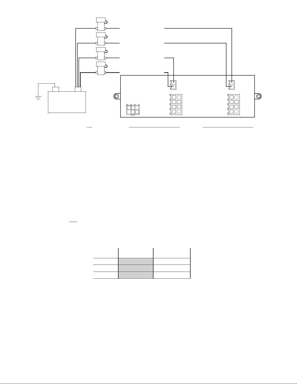
J2 Outputs 5 - 8
J3 Outputs 5 - 8
J2 Outputs 1 - 4
Using appropriately
sized wire, extend
the input wires to
fuse blocks installed
at the battery.
Connect each fuse
block individually
to the Pos. (+)
battery terminal.
Each input wire
must be fused
independently.
J3 Outputs 1 - 4
J2 (2.5A MAX per outlet)
1 - Output 9
2 - Output 10
3 - Output 11
4 - Output 12
5 - Output 13
6 - Output 14
7 - Output 15
8 - Output 16
J3 (2.5A MAX per outlet)
1 - Output 1
2 - Output 2
3 - Output 3
4 - Output 4
5 - Output 5
6 - Output 6
7 - Output 7
8 - Output 8
J2 J3
J1
J1
1 - Not Used
2 3 - Black (Ground)
4 - Green (CAN A)
5 6 - Grey (CAN B)
14253
6
(10A)
(10A)
(10A)
(10A)
1
5
2
6
3
7
4
8
1
5
2
6
3
7
4
8
(+)
Battery
(-)
5 Amps 10 Amps
18 AWG
16 AWG
14 AWG
15 Feet 7.5 Feet
24 Feet 12 Feet
39 Feet 19.5 Feet
Wire
Gauge
Current Draw
Wire Gauge Calculation Chart
To use this chart...
1. Determine the amount of current being drawn through the wire. Locate this
number in the top row. If the current value is between adjacent values, use the
higher number.
2. Follow this column down until the length of the installed wire is shown. If the exact
length is between adjacent values, use the higher number. The wire gauge shown
for this row represents the minimum size wire that should be used.
IMPORTANT! This product was designed to be configured using the WeCan system programming software. It can not
be used as a stand alone module.
WARNING! All customer supplied wires that connect to the positive terminal of the battery must be sized to supply at
least 125% of the maximum operating current and fused ‘at the battery to carry that load. DO NOT USE CIRCUIT
BREAKERS WITH THIS PRODUCT!
Addressing - The network address for this module is pre-configured to be identified in the configuration software as
“MODULE 1”. If two (2) REMOTE16 modules are installed, it will be necessary to cut the jumper wire located between
J1-2 and J1-5, on one
of the modules. That module will now be identified in the configuration software as “MODULE 2”.
Page 2
Page 3

J2 - 2.5A MAX per Outlet
Pos. Outlet Color Function Location Activated By
J3 -
J2-1 9 BRN __________________________________________________________ _____________________________ ______________________
J2-2 10 RED
J2-3 11 ORG
J2-4 12 YEL
J3-5 5 WHT/GRN
J3-6 6 WHT/BLU
J3-7 7 WHT/VIO
J3-8 8 WHT/GRY
__________________________________________________________ _____________________________ ______________________
__________________________________________________________ _____________________________ ______________________
__________________________________________________________ _____________________________ ______________________
J2-5 13 GRN __________________________________________________________ _____________________________ ______________________
J2-6 14 BLU __________________________________________________________ _____________________________ ______________________
J2-7 15 VIO __________________________________________________________ _____________________________ ______________________
J2-8 16 GRY __________________________________________________________ _____________________________ ______________________
J3-1 1 WHT/BRN __________________________________________________________ _____________________________ ______________________
J3-2 2 RED __________________________________________________________ _____________________________ ______________________
J3-3 3 ORG __________________________________________________________ _____________________________ ______________________
J3-4 4 YEL __________________________________________________________ _____________________________ ______________________
__________________________________________________________ _____________________________ ______________________
__________________________________________________________ _____________________________ ______________________
__________________________________________________________ _____________________________ ______________________
__________________________________________________________ _____________________________ ______________________
Pos. Output Color Function Location Activated By
2.5A MAX per Outlet
WHT/
WHT/
WHT/
This worksheet has been provided so that a written record of all Input, Output and Axillary
connections may be created. After all pertinent installation data has been verified and
recorded, store and retain this sheet for future reference.
REMOTE16™Installation Worksheet
(J2 & J3)
11
55
22
66
33
77
44
88
J2 J3
Page 3
 Loading...