

Page 1

®
ENGINEERING COMPANY INC.
51 Winthrop Road
Chester, Connecticut 06412-0684
Installati on Guide:
Centurion™ Lightbar
Phone: (860) 526-9504
Fax: (860) 526-4078
Internet: www.whelen.com
Sales e-mail: autosale@whelen.com
Canadian Sales e-mai l: auto can@whelen.com
Customer Service e-mail: custserv@whelen.com
Safety First
This document provid es all the nec es sa ry in form at ion to allow your Whelen prod uc t to b e pro perl y a nd s afe ly ins tal le d.
Before beginning the installation and/or operation of your new product, the installation technician and operator must
read this manual completely. Important information is contained herein that could prevent serious injury or damage.
• Proper installation of this product requires the installer to have a good understanding of automotive electronics,
systems and proced ur es.
• If mounting this product requires drilling holes, the installer MUST be sure that no vehicle components or other
vital parts could be damaged by the drilling process. Check both sid es of the mo unting sur f ace bef ore drilling
begins. Also de-burr any holes and remove any metal shards or remnants. Install grommets into all wire
passage holes.
• If this manual states that this product may be mounted with suction cups, magnets, tape or Velcro®, clean the
mounting surface with a 50/50 mix of isopropyl alco hol and wa te r and dry thoroughly.
• Do not install this product or route any wires in the deployment area of your air bag. Equipment mounted or
located in the air bag deployment area will damage or reduce the effectiveness of the air bag, or become a
projectile that could cause serious personal injury or death. Refer to your vehicle owner’s manual for the air bag
deployment area. The User/Installer assumes full responsibility to deter m ine pr oper mounting location, based
on providing ultimate safet y t o al l passenge rs ins id e the vehicle.
• For this product to operate at optim u m ef f icie ncy, a good electrical connec tion t o chassis ground must be
made. The recommended procedure requires the product ground wire to be connected directly to the NEGATIVE
(-) battery post.
• If this product uses a rem ote d evice to activate or control th is product, make sure that th is control is located in
an area that allows both the vehicl e a nd th e control to be operated safely in any dr i vi ng co ndi tion.
• Do not attempt to activate or con trol this device in a hazardous driving si tu at io n.
• This product contains either strobe light(s), halogen light(s), high-intensity LEDs or a com bination of these
lights. Do not stare directly into these lights. Momentary blindness and/or eye damage could result.
• Use only soap and water to clean the outer lens. Use of other chemicals could result in premature lens cracking
(crazing) and discoloration. Lenses in this cond ition hav e sign ificantly reduced effectiveness and should be
replaced immediately. Inspect and operate this product regularly to confirm its proper operation and mountin g
condition. Do not use a pre ss u re w asher to clean this product.
• It is recommended tha t th ese instructions be stored i n a safe place and referred t o w hen performing
maintenance and/or reinstallation of this product.
• FAILURE TO FOLLOW THESE SAFETY PRECAUTIONS AND INSTR UCTIONS COUL D RESULT IN DAMAGE TO
THE PRODUCT OR VEHICLE AND/OR SERIOUS INJURY TO YOU AND YOUR PASSENGERS!
Automotive: Lightbars
For warranty information regarding this product, visit www.whelen.com/warranty
©1998 Whelen Engineering Company Inc.
Form No.13317F (062210)
Page 1
Page 2
IMPORTANT! The lightbar should be located a minimum of
16" from any radio antennas!
Permanent Mounting:
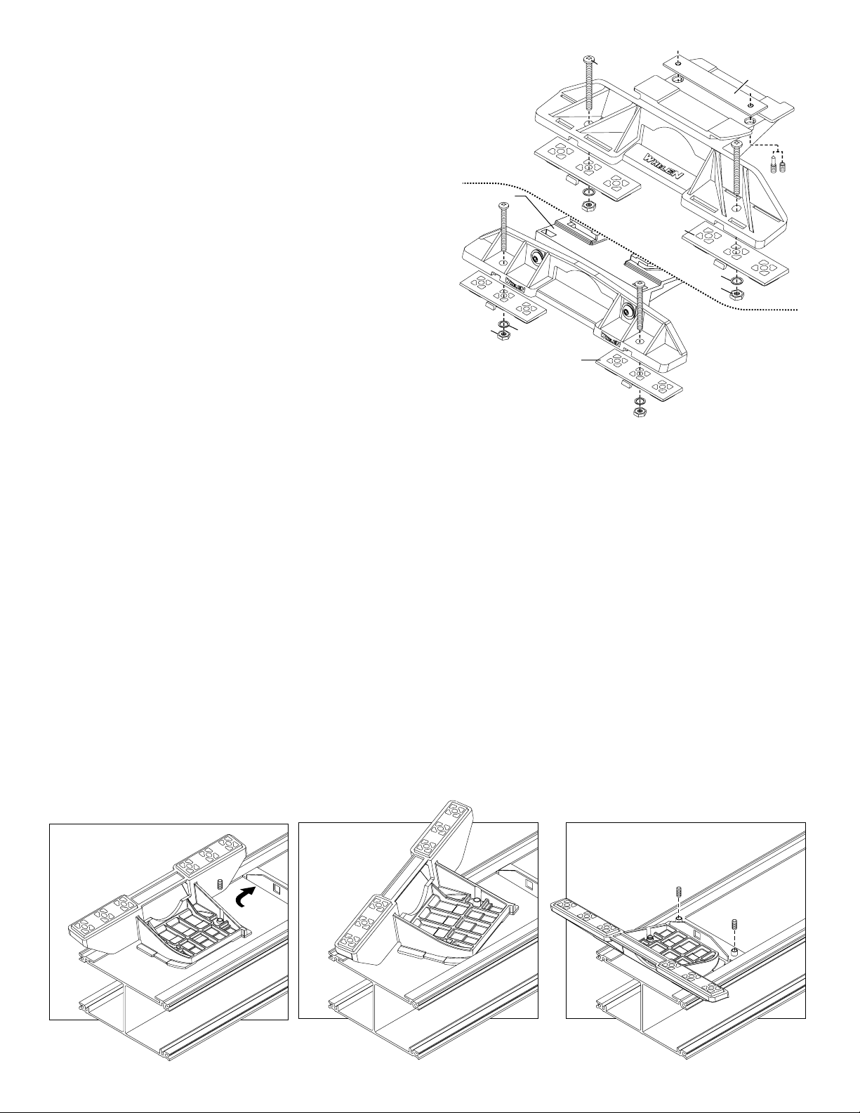
1. Locate the mounting foot and locking plate included with your
lightbar. If not already present, install the locking plate onto the
mounting foot. When properly positioned, this plate is centered from
side to side on the mounting foot.
2. Flip the lightbar upside-down to expose the bottom of the extrusion
and place the mounting foot onto the extrusion.
3. Rotate the mounting foot 90° in a counter-clockwise direction. Make
sure that the edges of the mounting foot swing into position under the
extrusion mounting lip.
4. Repeat this procedure for the remaining mounting foot and return the
lightbar to its right side-up position.
5. Position the lightbar onto the vehicle roof in the desired mounting
location. One often selected location is directly above the B-pillars.
This area is the strongest part of the roof. Refer to your lightbar
manual for cable exit location, to be sure that the lightbar is facing the
proper direction.
6. Adjust the two mounting feet outwards so that they are as close to
the edge of the roof as possible. Make s ure that both mounting feet
are in full contact with the roof. Be sure that there is no less than 1/2”
clearance between the roof and the lightbar at their closest point.
When the mounting feet are in their proper position, lightly tighten the
locking plate allen head set screws.
7. Turn the lightbar upside down and firmly tighten all of the set screws
from step 6 (2 or 4 per side).
8. On the adjustable foot, use the hole in the pad as a guide to drill the
two holes into the mounting foot at the locations shown.
Standard
Mounting
Bolt
Bolt
Locking
Plate
Foot
Mounting
Foot
Base
Nut
Washer
Mounting
Pad
9. Place the lightbar in its final mounting position on the vehicle, mark
the mounting hole locations off onto the mounting surface, remove
the lightbar and drill the mounting holes.
10. Place the lightbar back onto the vehicle lined up with the mounting
holes and secure the mounting feet to the vehicle with the supplied
hardware.
Mounting
Pad
Washer
Nut
Adjustable
Mounting
Foot
Strap Mounting:
1. Locate the mounting foot, anchor plate and locking plate included with
your lightbar. If not already present, install the locking plate onto the
mounting foot. When properly positioned, this plate is centered from sideto-side on the mounting foot.
2. Flip the lightbar upside-down to expose the bottom of the extrusion and
place the mounting foot onto the extrusion.
3. Rotate the mounting foot 90° in a counter-clockwise direction. Make sure
that the edges of t he mounting f oot s wing int o p ositi on u nde r t he ex tru sion
mounting lip. Install an anchor plate onto the extrusion in the same
manner.
4. Repeat this procedure for the remaining mounting foot and anchor plate
and return the lightbar to its right side-up position.
5. Position the lig htbar ont o the v eh icle ro of in the d esi red mou nt ing locat ion .
One often selected location is directly above the B-pillars. This area is the
strongest part of the roof. Refer to your lightbar manual for cable exit
location, to be sure that the lightbar is facing the proper direction.
6. Adjust the two mounting feet outwards so that they are as close to the
edge of the roof as possible. Both mounting feet must be in full contact
with the roof. Be sure that there is no less than 1/2” clearance between
Insert foot into extrusion with locking plate
attached.
ANCHOR
PLATE
Twist mounting foot into
position
roof and lightbar at their closest poin t. When the mounti ng feet are in the ir
proper position, lightly tighten the locking plate allen head set screws.
7. Return the lightbar to an upside-down position. Slide each anchor plate
outwards until it is fully engaged with its corresponding mounting foot.
With the mounting feet and anchor plates in their proper positions firmly
tighten all of the s et screws (2 or 4 per side). Flip the lightba r right side-up
and return it to its mounting position.
8. Open both drivers side doors. In the area directly below the mounting
foot, pull the weatherstrip away from the vehicle so the area where the
mounting strap will be secured is expos ed. Repeat for the other side.
9. Insert the mounting strap through the mounting foot. Be sure that the
strap fits flush against the area where it will be secured onto the vehicle.
Insert the tension bolt through the mounting strap and anchor plate, into
the tinnerman nut. Tighten slightly with a long-shafted, Phillips
screwdriver. Repeat procedure for pas senger side.
10. If your mounting strap has mounting holes in the end of the strap, use
these holes as a template to drill appropriately sized pilot holes through
the strap and into the vehicle. Repeat for passenger side of the vehicle.
11. Firmly tighten the tension bolt s t o secure the lightbar to the vehicle.
Loosely secure foot and locking plate.
Page 2
Page 3

NOTE: Model MKAJ is an adjustable mounting foot. On this model you
may loosen the screws on the rear of the foot and adjust the angle of the
lightbar. This feature can be used if the angle of the roof is not level with
the road. IMPORTANT: To adjust the leveling screws you must use a
torque wrench set at 35 to 40in./lbs.
Adjustable Foot
Model MKAJ
Tension
Bolt
Mounting
Screw
Adjustment
screws
Lock
Washer
5" Mounting Foot
METAL SCREW
SHEET
METAL
SCREWS
NOTE: The mounting straps are made to fit the contours of individual
NOTE:
NOTE:
NOTE:
NOTE:
NOTE:
NOTE:
Mounting Strap
Locking
BOLT
STRAP
vehicles. The strap
for your vehicle
mounting foot, it will assemble differently than the standard
mounting foot. It also uses an extension to compensate for
the extra height. Follow these illustrations for assembly.
Mounting to the lightbar is the same.
Anchor Plate
Plate
Tinnerman
Nut
Nut
Mounting
Foot
Mounting
Pad
MOUNTING FOOT
EXTENSION
SPLIT LOCK
WASHER
shown here is for example only. The strap
may look different. If your lightbar has a 5"
Allen
screws
Mounting
Foot Base
NUT
Model
MKAJ
Tighten screws
with torque wrench
set at 35 to 40 in/lbs
Mounting
Screw
TINNERMAN
NUT
FOOT
ANCHOR
PLATE
VEHICLE ROOF
Mounting
Strap
Tension
Bolt
Plate slides into
lightbar extrusion
SET
SCREW
Locking
Plate
Standard Foot
Anchor
Plate
Model MKEZ
Tinnerman
Nut
Mounting
Foot
IMPORTANT: For strap mounted bars, be sure you have the right sized
lightbar for your vehicle. The lightbar should be approximately the same
width as the vehicle roof. If too large or small it will not mount properly
1/2" MIN. CLEARANCE
NOTE: Unless otherwise specified, the lightbar mounting feet must be sitting as close to the edge of the roof as possible. They must also be
in full contact with the roof and not be hanging off the edge.
to the vehicle and may come loose during driving.
Page 3
Page 4

Routing your Edge® Lightbar Cable(s)
1. To protect the headliner from damage caused by drilling the cable access
hole through the vehicle roof, allow a 5” to 7” distance between roof and
headliner by lowering the headliner before drilling.
2. Using a 1” hole saw, drill the cable access hole.
NOTE:There may be a roof support member that spans the distance between
the driver’s and passenger’s side. DO NOT DRILL THROUGH THIS MEMBER!
Adjust the location un til the hole can be drilled without contacting this support member.
3. Use a round file to smooth and de-burr the edges of the hole.
4. Insert a 1” grommet (user supplied) into the cable access hole.
5. Insert the cable(s) through the cable access hole into the vehicle. Use RTV
silicone to weatherproof the access hole after the cable(s) are pulled
completely into the vehicle.
6. Route the cable(s) down through the B-pillar. The cable(s) must make a 90°
turn to enter the B-pillar. Although routing the cable in this manner may be
difficult, this has been determined to be the best procedure. It is up to the
installation technicians discretion whether to route the cable(s) as
recommended or use an alternative route. Pull the full length of the cable(s)
out of the hole at the base of the B-pillar (Fig. 1) and route towards your
switch panel. Refer to the instructions included with your switches for switch
wiring information.
NOTE: The outer surfaces of this product may be cleaned with mild
soap and water. Use of any other chemicals may void product warranty. Do not use a pressure washer.
Fig. 1
DRILLING THE CABLE ACCESS HOLE
FRONT OF LIGHTBAR
For
lightbars
cables exiting
with
the Driver-side
of the extrusion
Drill cable access hole in appropriate area
for your lightbar (see note)
CABLE EXIT HOLE
F
R
O
N
T
For
lightbars
cables exiting
with
the Passenger-side
of the extrusion
B-PILLAR
(INSIDE VIEW)
WIRE SHIELD
WIRING DIAGRAM
(8/C 14GA CABLE)
+ POS. DC INPUT
CABLE INPUT LOCATION
FRONT
BROWN - (REAR FLASHER OR OTHER DESIRED OPTION)
RED - (OUTBOARD ROTATOR)
ORANGE - (CENTER ROTATOR )OR OTHER DESIRED OPTION
YELLOW - (DRIVER ALLEY )OR OTHER DESIRED OPTION
GREEN - (PASS. ALLEY )OR OTHER DESIRED OPTION
BLUE - (INBOARD ROTATOR )OR OTHER DESIRED OPTION
VIOLET - (FRONT FLASHER )OR OTHER DESIRED OPTION
GRAY - (TAKEDOWN )OR OTHER DESIRED OPTION
BLACK - TO NEGATIVE TERMINAL OF BATTERY
Page 4
 Loading...