

Page 1

®
ENGINEERING COMPANY INC.
CAUTION
Loud siren noise can cause
hearing damage and/or loss.
Refer to OSHA Section 1910.95 prior
to putting ANY siren into service!
Wear
Protection!
ACTIVATION OF THIS
SIREN MAY DAMAGE
UNPROTECTED EARS!
51 Winthrop Road
Chester, Connecticut 06412-0684
Phone: (860) 526-9504
Fax: (860) 526-4078
Internet: www.whelen.com
Sales e-mail: autosale@whelen.com
Canadian Sales e-mail: canadiansales@whelen.com
Customer Service e-mail: custserv@whelen.com
DANGER! Sirens produce extremely loud emergency warning tones! Exposure to these tones without proper and adequate hearing protection,
could cause ear damage and/or hearing loss! The Occupational Safety & Health Administration (www.osha.gov) provides information necessary to
determine safe exposure times in Occupational Noise Exposure Section 1910.95. Until you have determined the safe exposure times for your
specific application, operators and anyone else in the immediate vicinity should be required to wear an approved hearing protection device.
FAILURE TO FOLLOW THIS RECOMMENDATION COULD CAUSE HEARING LOSS!
Whelen’s emergency vehicle warning devices must be properly mounted and wired in order to be effective and safe. Read and follow all of Whelen’s
written instructions when installing or using this device. Emergency vehicles are often operated under high speed stressful conditions which must be
accounted for when installing all emergency warning devices. Controls should be placed within convenient reach of the operator so that he can operate
the system without taking his eyes off the roadway. Emergency warning devices can require high electrical voltages and/or currents. Properly protect and
use caution around live electrical connections.Grounding or shorting of electrical connections can cause high current arcing, which can cause personal
injury and/or vehicle damage, including fire. Many electronic devices used in emergency vehicles can create or be affected by electromagnetic
interference. Therefore, after installation of any electronic device it is necessary to test all electronic equipment simultaneously to insure that they operate
free of interference from other components within the vehicle. Never power emergency warning equipment from the same circuit or share the same
grounding circuit with radio communication equipment. All devices should be mounted in accordance with the manufacturer’s instructions and securely
fastened to vehicle elements of sufficient strength to withstand the forces applied to the device. Driver and/or passenger air bags (SRS) will affect the way
equipment should be mounted. This device should be mounted by permanent installation and within the zones specified by the vehicle manufacturer, if
any. Any device mounted in the deployment area of an air bag will damage or reduce the effectiveness of the air bag and may damage or dislodge the
device. Installer must be sure that this device, its mounting hardware and electrical supply wiring does not interfere with the air bag or the SRS wiring or
sensors. Mounting the unit inside the vehicle by a method other than permanent installation is not recommended as unit may become dislodged during
swerving; sudden braking or collision. Failure to follow instructions can result in personal injury. Whelen assumes no liability for any loss resulting from the
use of this warning device. PROPER INSTALLATION COMBINED WITH OPERATOR TRAINING IN THE PROPER USE OF EMERGENCY WARNING
DEVICES IS ESSENTIAL TO INSURE THE SAFETY OF EMERGENCY PERSONNEL AND THE PUBLIC.
Whelen’s emergency vehicle warning devices are intended to alert other operators and pedestrians to the presence and operation of emergency vehicles
and personnel. However, the use of this or any other Whelen emergency warning device does not guarantee that you will have the right-of-way or that
other drivers and pedestrians will properly heed an emergency warning signal. Never assume you have the right-of-way. It is your responsibility to proceed
safely before entering an intersection, driving against traffic, responding at a high rate of speed, or walking on or around traffic lanes. Emergency vehicle
warning devices should be tested on a daily basis to ensure that they operate properly. When in actual use, the operator must ensure that both visual and
audible warnings are not blocked by vehicle components (i.e.: open trunks or compartment doors), people, vehicles, or other obstructions. It is the user’s
responsibility to understand and obey all laws regarding emergency warning devices. The user should be familiar with all applicable laws and regulations
prior to the use of any emergency vehicle warning device. Whelen’s audible warning devices are designed to project sound in a forward direction away
from the vehicle occupants. However, because sustained periodic exposure to loud sounds can cause hearing loss, all audible warning devices should be
installed and operated in accordance with the standards established by the National Fire Protection Association.
Safety First
This document provides all the necessary information to allow your Whelen product to be properly and safely installed. Before beginning the installation
and/or operation of your new product, the installation technician and operator must read this manual completely. Important information is contained herein
that could prevent serious injury or damage.
• Proper installation of this product requires the installer to have a good understanding of automotive electronics, systems and procedures.
• Whelen Engineering requires the use of waterproof butt splices and/or connectors if that connector could be exposed to moisture.
• Failure to use specified installation parts and/or hardware will void the product warranty.
• If mounting this product requires drilling holes, the installer MUST be sure that no vehicle components or other vital parts could be damaged
by the drilling process. Check both sides of the mounting surface before drilling begins. Also de-burr the holes and remove any metal shards
or remnants. Install grommets into all wire passage holes.
• If this manual states that this product may be mounted with suction cups, magnets, tape or Velcro®, clean the mounting surface with a 50/50
mix of isopropyl alcohol and water and dry thoroughly.
• Do not install this product or route any wires in the deployment area of your air bag. Equipment mounted or located in the air bag deployment
area will damage or reduce the effectiveness of the air bag, or become a projectile that could cause serious personal injury or death. Refer to
your vehicle owner’s manual for the air bag deployment area. The User/Installer assumes full responsibility to determine proper mounting
location, based on providing ultimate safety to all passengers inside the vehicle.
• For this product to operate at optimum efficiency, a good electrical connection to chassis ground must be made. The recommended
procedure requires the product ground wire to be connected directly to the NEGATIVE (-)
battery post (this does not include products that use cigar power cords).
• If this product uses a remote device for activation or control, make sure that this device is
located in an area that allows both the vehicle and the device to be operated safely in any
driving condition.
• It is recommended that these instructions be stored in a safe place and referred to when
performing maintenance and/or reinstallation of this product.
• FAILURE TO FOLLOW THESE SAFETY PRECAUTIONS AND INSTRUCTIONS COULD RESULT IN
Automotive: Sirens/Switches
DAMAGE TO THE PRODUCT OR VEHICLE AND/OR SERIOUS INJURY TO YOU AND YOUR
PASSENGERS!
©2013 Whelen Engineering Company Inc.
Form No.14702A (073014)
Installation Guide:
Broadcaster Audio Playback Module
Warnings to Installers
Warnings to Users
For warranty information regarding this product, visit www.whelen.com/warranty
Page 1
Page 2
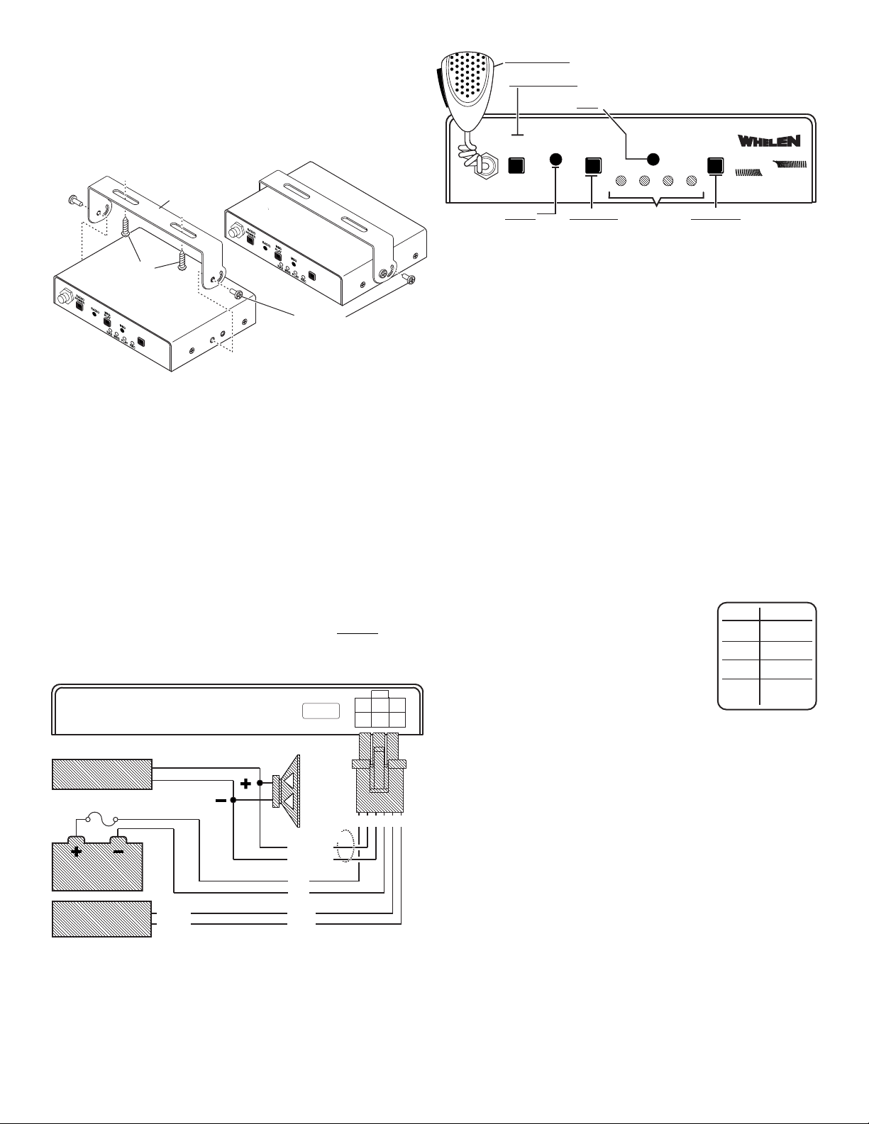
Installation:
RAD
MSG
PLAY
REC
LED
No Tone
YELP
Piercer
Pulsed
Airhorn
TONE
RADIO
RADIO
POWER
MSG
SIREN
SEL
MSG
PLAY
RAD
MSG
PLAY
REC
Play or Cancel
a message
MSG PLAY
Select Pre-Tones
SIREN SEL
RADIO POWER Power Up / Power Down / Choose Radio or Message
RADIO
Adjust 2-Way
radio volume
MSG Adjust the volume of an outgoing message
MICROPHONE Record messages
LED's
MANUFACTURED IN U.S.A.
BROAD
CASTER
BROAD
CASTER
SIREN
SELECT
SIREN
SELECT
Bail Strap
#6-32 X 1/4
Phillips Pan Head
Machine Screw
SW2
SW3
SW
1
SW
2
SW
3
SW
1
BAIL STRAP MOUNT
8X1/2
Phillips Pan
Head Sheet
Metal Screw
BATTERY
2-WAY RADIO
FUSE @ 5 AMPS
3
6
251
4
5 AMP
SIREN
AMPLIFIER
SIREN
AMPLIFIER
BLUE
BLUE
36
2514
RADIO
REPEAT
INPUTS
REAR VIEW
WIRING DIAGRAM
RED
BLK
OPTIONAL
WHT/BLU
WHT/BLU
BATTERY
2-WAY RADIO
SIREN
AMPLIFIER
Caution: Permanent mounting of this product will require
drilling. It is absolutely necessary to make sure that no other
vehicle components could be damaged by this process. Check
both sides of the mounting surface before starting. If damage is
likely, select a different mounting location.
1. Position the bail strap in the mounting location. Scribe the surface
where the mounting holes are to be drilled.
2. Carefully drill the mounting holes in the areas scribed in step one.
Size the drill bit for the supplied 8 X 1/2” Phillips Pan Head Sheet
Metal Screws.
3. Secure the bail strap to the mounting location using the supplied
mounting hardware.
4. With the bail strap in place, insert the supplied #6 - 32 X 1/4 Phillips
Pan Head Machine Screws through the holes in the side of the bail
strap and into the holes in the control head on both sides and
tighten the hardware securing the control head.
Wiring:
WARNING! All customer supplied wires that connect to the
positive terminal of the battery must be sized to supply at least
125% of the maximum operating current and FUSED
battery to carry that load. DO NOT USE CIRCUIT BREAKERS
WITH THIS PRODUCT!
at the
Operation and Programming:
Powering On & Off:
1. Press and release the POWER button and the unit will power up
in Radio Pass Mode.
2. Press and release again to toggle between Radio Pass Mode &
Message Broadcast Mode.
3. PRESS and HOLD - (for 1 second) to power down.
To Record a Message:
1. Press the microphone button in and hold until the REC LED turns
on, then talk into the microphone to record the message.
2. When the message is complete, release the microphone lever.
To Play a Message:
1. Press the MSG PLAY button to play the message back once, or
press and hold the MSG PLAY button until the PLAY LED turns
on (1 sec.) to repeat the message continuously
2. Press the MSG PLAY or POWER button to cancel the message.
To Choose a Siren Tone that will sound
before the recorded voice message:
1. Press and release the SELECT button to
cycle through the four LED indicators on
the front panel. Each LED indicates either a
tone or no tone (see chart).
2. When the LED flashes, that tone is chosen.
3. Press the button again to choose a new
tone.
To adjust the radio volume:
1. Set the radio volume on your siren amplifier to the middle
position.
2. Next, using a flat blade screwdriver, turn the screw in the port on
the front of the unit labeled RADIO (clockwise to increase,
counterclockwise to decrease).
3. If the volume is too loud or soft, adjust further using the volume
control on the radio.
To adjust the message volume:
1. Set the radio volume on your siren amplifier to the middle
position.
2. Next, using a flat blade screwdriver, turn the screw in the port on
the front of the unit labeled MSG (clockwise to increase,
counterclockwise to decrease).
Page 2
 Loading...