

Page 1

®
ENGINEERING COMPANY INC.
51 Winthrop Road
Chester, Connecticut 06412
Phone: (860) 526-9504
B6R, B6T and B6R M7 Series
Installation Guide:
Warning Lights
Fax: (860) 526-4078
Internet: www.whelen.com
Sales e-mail: autosale@whelen.com
Canadian Sales e-mail: autocan@whelen.com
Customer Service e-mail: custserv@whelen.com
Safety First
This document provides all the necessary information to allow your Whelen product to be properly and safely installed.
Before beginning the installation and/or operation of your new product, the installation technician and operator must
read this manual completely. Important information is contained herein that could prevent serious injury or damage.
• Proper installation of this product requires the installer to have a good understanding of automotive electronics,
systems and procedures.
• If mounting this product requires drilling holes, the installer MUST be sure that no vehicle components or other
vital parts could be damaged by the drilling process. Check both sides of the mounting surface before drilling
begins. Also de-burr the holes and remove any metal shards or remnants. Install grommets into all wire passage
holes.
• If this manual states that this product may be mounted with suction cups, magnets, tape or Velcro™, clean the
mounting surface with a 50/50 mix of isopropyl alcohol and water and dry thoroughly.
• Do not install this product or route any wires in the deployment area of your air bag. Equipment mounted or
located in the air bag deployment area will damage or reduce the effectiveness of the air bag, or become a
projectile that could cause serious personal injury or death. Refer to your vehicle owners manual for the air bag
deployment area. The User/Installer assumes full responsibility to determine proper mounting location, based
on providing ultimate safety to all passengers inside the vehicle.
• For this product to operate at optimum efficiency, a good electrical connection to chassis ground must be
made. The recommended procedure requires the product ground wire to be connected directly to the NEGATIVE
(-) battery post (this does not include products that use cigar power cords).
• If this product uses a remote device for activation or control, make sure that this device is located in an area
that allows both the vehicle and the device to be operated safely in any driving condition.
• Do not attempt to activate or control this device in a hazardous driving situation.
• This product contains either strobe light(s), halogen light(s), high-intensity LEDs or a combination of these
lights. Do not stare directly into these lights. Momentary blindness and/or eye damage could result.
• Use only soap and water to clean the outer lens. Use of other chemicals could result in premature lens cracking
(crazing) and discoloration. Lenses in this condition have significantly reduced effectiveness and should be
replaced immediately. Inspect and operate this product regularly to confirm its proper operation and mounting
condition. Do not use a pressure washer to clean this product.
• It is recommended that these instructions be stored in a safe place and referred to when performing
maintenance and/or reinstallation of this product.
• FAILURE TO FOLLOW THESE SAFETY PRECAUTIONS AND INSTRUCTIONS COULD RESULT IN DAMAGE TO
THE PRODUCT OR VEHICLE AND/OR SERIOUS INJURY TO YOU AND YOUR PASSENGERS
!
Automotive: Beacons
For warranty information regarding this product, visit www.whelen.com/warranty
©2003 Whelen Engineering Company Inc.
Form No.13661F (022310)
Page 1
Page 2
y
Standard Mounting
TOP VIEW
MOUNTING
HOLES
MOUNTING
SCREWS
(Standard
mounting)
#10 X 3/4"
PPHSMS
LENS
#10 X 3/4"
PPHSMS
TYPE "A"
CLAMP RING
CLAMP
RING
Thru Hole Mounting
FRONT VIEW / CROSS SECTION
FASTEX
GROMMET
BASE
1¾"
3½"
WIRE
HOLE
1¾"
MOUNTING
SURFACE
MOUNTING
GASKET
This warning light combines a rotating beacon and
an LED lighthead for double warning. It also meets new
NFPA standards for rear upper Zone “C” applications.
MOUNTING
SURFACE
Installation:
Before installation, read all warnings on the previous page.
1. Dismantle the light by first removing the screw which
fastens the clamp ring that holds lens on and remove the
lens.
MOUNTING SCREWS
(Thru Hole Mounting)
2. Position the base housing onto the vehicle so that the lower light
device is facing directly rearward, locate the three mounting holes drilled into the base housing (See above) and
mark them off on the mounting surface of the vehicle.
3. Remove the unit and position the base gasket onto the vehicle. Line the gasket up with the marks you
made for the mounting screws and mark off the center wire access hole.
4. Drill the base mounting holes for the three #10 sheet metal screws and for the center wire access
hole (Grommet as needed. Customer supplied).
5. Feed the wires out of the unit, through the mounting gasket and through the access hole and
connect them to your power source. (See wiring)
6. Attach the base to the vehicle with the 3 sheet metal screws supplied,
then reassemble and test the unit.
OPTIONAL MOUNTING: To install the unit using “Thru Hole
Mounting”, on the mounting surface, drill two holes, sized for a
¼” sheet metal screw following the diagram above. Be sure
that these markings reflect the desired direction that the unit
OPTIC
LENS
700 SERIES
LINEAR TIR
GROMMET
LED FLASHER
will face once installed. Insert the customer supplied screws up
through the bottom of the base and tighten to secure.
WARNING! All customer supplied wires that connect to
the positive terminal of the battery must be sized to supply
at least 125% of the maximum operating current and
FUSED
at the battery to carry that load. DO NOT USE
CIRCUIT BREAKERS WITH THIS PRODUCT!
#6 X 1-1/4"
PPHSMS
Lo Intensity / Violet Wire: This feature allows the user
to step the unit down to low power operation for nighttime use.
Apply positive voltage to the VIOLET wire to put the lighthead into low power. Remove voltage
from the VIOLET wire to restore high power operation.
Scan-Lock™/ White-Violet Wire: Flash pattern selection.
To change flash patterns, first turn the lighthead on:
TO CYCLE THROUGH ALL PATTERNS: Apply +12 volts to the WHITE-VIOLET wire for
less than 1 second and release to cycle forward. Apply +12 volts to the WHITE-VIOLET
wire for more than 1 second and release to cycle backward.
TO SET A PATTERN AS DEFAULT: Allow the desired pattern to run for more than 5
seconds. The lighthead will now display this pattern when active.
TO RESET TO THE FACTORY DEFAULT PATTERN: Turn off power, apply +12 volts to
the WHITE-VIOLET wire, turn power on.
IMPORTANT WARNING!
CAUTION! DO NOT LOOK DIRECTLY AT THESE LED’S WHILE THEY ARE ON.
MOMENTARY BLINDNESS AND/OR EYE DAMAGE COULD RESULT!
Page 2
FLASH PATTERNS:
FLASH PATTERNS:
SignalAlert™ 75
1.
SignalAlert™ 150
2.
SingleFlash 375
3.
SingleFlash 150
4.
SingleFlash 75
5.
DoubleFlash 150
6.
DoubleFlash 75
7.
CometFlash® 75
8.
ActionFlash™
9.
ModuFlash™
10.
ComAlert™
11.
ActionScan™
12.
MOUNTING
GASKET
LED MOUNTING
BRACKET
GROMMET
M7/B6 ADAPTOR
M7 GASKET
M7 SERIES
SignalAlert™
13.
Steady
14.
Steady-Brake
15.
FLASH PATTERNS
FLASH PATTERNS
SPLIT / 4 WIRE:
SPLIT / 4 WIRE:
SignalAlert™ 75 Alt.
1.
SignalAlert™ 75 Sim.
2.
CometFlash® 75 Alt.
3.
CometFlash® 75 Sim.
4.
DoubleFlash 150 Alt.
5.
DoubleFlash 150 Sim.
6.
DoubleFlash 75 Alt.
7.
DoubleFlash 75 Sim.
8.
#6 - 32 X 1/2"
PPHMS S.S.
#6 INTERNAL TOOTH
LOCK WASHER S.S.
ROTATING MECH
128 FPM 12V
SNAP-IN BULB
(INSIDE) 12V / 60W
34-0041987-07
REPLACEMENT
LAMP 12V 50W
34-0041987-06
ROTATING MECH
12V 50W
B6R HOUSING
WIRING:
BLACK
FLASHER
or
LINEAR
TIR
or
SPLIT
FLASHER
or
M7
9.
10.
11.
12.
13.
14.
15.
16.
17.
18.
19.
20.
(-) GROUND
RED
+12V INPUT
WHT-VIO
Scan-Lock™
(-) GROUND
BLACK
Low Power
VIOLET
+12V INPUT
RED
WHT-VIO Scan-Lock™
BLACK
(-) GROUND
WHITE
+12V INPUT
RED
+12V INPUT
WHT-VIO Scan-Lock™
(-) GROUND
BLACK
+12V INPUT (SPLIT)
WHITE
+12V INPUT
RED
WHT-VIO Scan-Lock™
SingleFlash 375 Alt.
SingleFlash 375 Sim.
SingleFlash 150 Alt.
SingleFlash 150 Sim.
SingleFlash 75 Alt.
SingleFlash 75 Sim.
ActionFlash™ Alt.
ActionFlash™ Sim.
ModuFlash™ Alt.
ModuFlash™ - Sim.
ActionScan™
SSNF CH-1 Flash
CH-2 Stead
Page 3

GREEN-GREEN
BLUE-BLUE
WHITE-CLEAR
RED-RED
AMBER-AMBER
LED / Lens ColorA=B=C=G=R=1=2=4=5=J=K=M=6=D=
AMBER DUAL
Upper Dome Color
& Rotator Type
1= -
BLUE DUAL
CLEAR DUAL
2= -
3= -
GREEN DUAL
4= -
BLUE-CLEAR
AMBER-CLEAR
RED DUAL
5= -
AMBER-BLU-CLEAR
WHT-RED-WHT-RED
AMBER-RED-CLEAR
GREEN-CLEAR
RED-CLEAR
BLUE-RED-BLUE-RED
BLUE-RED-CLEAR
LINEAR TIR FLASHER
5mm FLASHER
M7 LED
LED Style5=M=
7=
WHT-RED-CLR
7=
LED STYLE
UPPER DOME COLOR
LED/LENS COLOR
01-0683693___
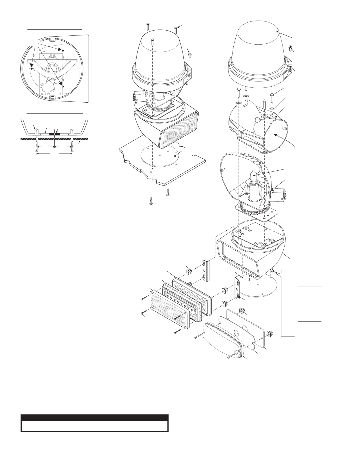
PART NUMBER KEY:
46
45
12 13 14
57 58 59 60
61 62 63
11
10
56
8
44
47 48 49 50
43
40
3
2
1
42
54
24
39
35 36 37
38
51
55
41
19
20
27
21
26
23
25
24
14
46
45
44
43
47 48 49 50
40
GREEN/GREEN
BLUE/BLUE
WHITE/CLEAR
RED/RED
AMBER/AMBER
LED/L Cens olorA=B=C=G=R=1=2=4=5=J=K=M=6=D=
BLUE/CLEAR
AMBER/CLEAR
AMBER/BLU/CLEAR
AMBER/RED/CLEAR
GREEN/CLEAR
RED/CLEAR
BLUE/RED/BLUE/RED
BLUE/RED/CLEAR
WHT/RED/WHT/RED
WHT/RED/CLR
7=
LED Style
Upper Dome Color
LED/Lens Color
12 13
57 58 59 60
61 62 63
11
10
56
8
91617
4567
3
2
42
1
LINEAR TIR FLASHER
5mm FLASHER
M7 LED
7=
Upper Dome Color
LED Style5=M=
35 36 37
24
38 39
GREEN/SINGLE
BLUE/SINGLE
CLEAR/SINGLE
AMBER/SINGLE
and Rotator TypeA=B=C=G=
RED/SINGLE
R=
01-0683693___
18
42
54
55
41
19
20
34
27
28
24
23
26
25
Page 3
21
29
52 53
30 31 32
Page 4

QTYQTY QTY
A/R
A/R
A/R
A/R
A/R
A/R
A/R
A/R
A/R
A/RA/R
A/RA/R
A/RA/R
REFREF REF
A/RA/R A/R
A/RA/R
REFREF REF
A/RA/R A/R
A/RA/R
A/RA/R
A/RA/R
A/RA/R
A/RA/R
A/R
A/R
A/R
A/R
A/R
A/R
A/R
ITEM
1
2
3
4
A/R
5
A/R
6
A/R
7
A/R
8
9
A/R
10
11
12
13
14
15
A/R
16
A/R
17
A/R
18
A/R
19
11
1
20
A/R
21
11
1
22
11
1
23
33
3
24
11
1
25
33
3
26
11
1
27
22
2
28
29
111
30
31
111
32
111
33
A/R
34
35
36
A/R
37
A/R
38
A/R
39
A/R
40
44
41
2
22
42
44
2
43
A/R
44
A/R
45
A/R
46
A/R
47
A/R
48
A/R
49
A/R
50
A/R
51
A/R
52
11
1
53
A/RA/R
54
1
55
1
56
2
57
58
59
60
61
62
63
PART NUMBER
01-06836935__
01-06836937__
01-0683693M__
01-0286419410
01-0286419420
01-0286419440
01-0283461-15
01-0283461-25
01-0283461-45
01-0283461-55
01-0286419450
01-0283461-35
01-0286419430
01-02864194A0
01-02864194B0
01-02864194G0
01-02864194R0
10-0522496-05
01-0283461-J5
01-0283461-D5
02-0382968-00
10-0320776-00
10-0522496-03
11-483144-011
01-0482951-00
14-062216-080
15-101416-120
16-0621020-32
19-261465-000
26-0215001-06
38-0242422-00
46-0942425-00
67-10118991800
67-10118221800
67-10118001800
25-0510223-05
21-12081205-3
68-4161381-10
68-4161381-20
68-4161381-30
68-4161381-40
68-4161381-50
15-061416-200
07-242837-000
13-062C40-16J
68-1183582-1S
68-1183582-2S
68-1183582-3S
68-1183582-4S
68-1183582-5S
02-0363417RBS
02-0363417RCS
02-0363417RAS
02-0382968-02
67-1011897180
67-1011877180
38-0143750-00
07-743879-000
15-081416-160
02-036A796-A0
02-036A796-B0
02-036A796-30
02-036A796-R0
02-036A796-10
02-036A796-20
02-036A796-50
B6R SERIES LED
B6R SERIES M7
B6R SERIES LINEAR TIR
700 LINEAR TIR AMBER 4 WIRE/ / CLEAR /
700 LINEAR TIR BLUE 4 WIRE/ / CLEAR /
700 LINEAR TIR GREEN 4 WIRE/ / CLEAR /
700 LED FLASHER AMBER/
700 LED FLASHER BLUE/
700 LED FLASHER GREEN/
700 LED FLASHER RED/
700 LINEAR TIR RED 4 WIRE/ / CLEAR /
700 LED FLASHER WHITE/
700 LINEAR TIR WHITE 4 WIRE/ / CLEAR /
700 LINEAR TIR AMB/ -AMB / 4 WIRE
700 LINEAR TIR BLU/ BLU- / 4 WIRE
700 LINEAR TIR / GRN-GRN / 4 WIRE
700 LINEAR TIR / RED-RED / 4 WIRE
LABEL MODEL B6T SERIES/
700 LED FLASHER - RED/BLUE
700 LED FLASHER - RED/WHITE
B6R ROT. MECH. 150 FPM-12V-50W
LABEL MADE IN USA FLAG/
LABEL MODEL B6R SERIES/
HOUSING MODEL B6R - POLISHED/
KIT PACKING B6R SERIES/
SCREW #6-32 X 1/2" PPHMS S.S./
SCREW #10 X 3/4" PPHSMS TYPE A/
WASHER #6 INTERNAL TOOTH LOCK S/S
CLAMP RING
TY-WRAP 6" BLACK/
GASKET MOUNTING/
HARNESS INPUT B6R ROTATOR/
WIRE 18 GA 18" WHITE/
WIRE 18 GA 18" RED/
WIRE 18 GA 18" BLACK/
BUTT TERMINAL 22-16 INLINE/
SCREW GROMMET, FASTEX
LENS B6R - AMBER/
LENS B6R - BLUE/
LENS B6R - CLEAR/
LENS B6R - GREEN/
LENS B6R - RED/
SCREW #6 X 1-1/4" PPHSMS/
LED MTG. BRACKET B6R HOUSING/
SCREW GROMMET #6 FASTEX/
LENS AMBER OPTIC SEAL/ with
LENS BLUE OPTIC SEAL/ with
LENS CLEAR OPTIC SEAL/ with
LENS GREEN OPTIC SEAL/ with
LENS RED OPTIC SEAL/ with
LENS RED BLUE OPTIC SEAL/ - with
LENS RED CLEAR OPTIC SEAL/ - with
LENS RED AMBER OPTIC SEAL/ - with
B6T ROT. MECH. 128 FPM-12V-50W
WIRE, 18 GA 18" WHT/VIO
WIRE 18 GA 18" VIOLET/
GASKET DIE CUT M7/
M7 TO B6R-B6T ADAPTOR PLATE
SCREW #8 X 1" PPHSMS/
SUB ASSY M7 SYNC AMB AMB/-
SUB ASSY M7 SYNC BLU BLU/-
SUB ASSY M7 SYNC WHT CLR/-
SUB ASSY M7 SYNC RED RED/-
SUB ASSY M7 SYNC AMB CLR/-
SUB ASSY M7 SYNC BLU CLR/-
SUB ASSY / M7 SYNC RED-CLR
DESCRIPTION
LINEAR TIR
LIGHTHEAD
BLACK (Ground)
VIOLET (Low Power)
LED Color (Power)
WHT/VIO (ScanLock™)
SPLIT FLASHER
LIGHTHEAD
BLACK (Ground)
LED #1 Color (Power)
LED #2 Color (Power)
WHT/VIO (ScanLock™)
FLASHER
LIGHTHEAD
BLACK (Ground)
LED Color (Power)
WHT/VIO (ScanLock™)
M7 SERIES
LIGHTHEAD
BLACK (Ground)
LED #1 Color (Power)
LED #2 Color (Power)
WHT/VIO (ScanLock™)
IMPORTANT! Before returning the vehicle to active service, visually
confirm the proper operation of this product, as well as all vehicle
components/equipment.
IMPORTANT! It is the responsibility of the installation technician to
make sure that the installation and operation of this product will not
interfere with or compromise the operation or efficiency of any
vehicle equipment!
CAUTION! Permanent mounting of this product will require drilling.
It is absolutely necessary to make sure that no other vehicle
components could be damaged by this process. Check both sides
of the mounting surface before starting. If damage is likely, select a
different mounting location.
WIRING DIAGRAMS
SPST Switch
SPST Switch
Momentary Switch
SPST Switch
SPST Switch
Momentary Switch
SPST Switch
Momentary Switch
SPST Switch
SPST Switch
Momentary Switch
Fuse - 5 Amp
Fuse - 5 Amp
Fuse - 5 Amp
Fuse - 5 Amp
Fuse - 5 Amp
Fuse - 5 Amp
(+)
Battery
(+)
Battery
(+)
Battery
(+)
Battery
(-)
(-)
(-)
(-)
Page 4
 Loading...