

Page 1

®
ENGINEERING COMPANY INC.
51 Winthrop Road
Chester, Connecticut 06412-0684
Phone: (860) 526-9504
Fax: (860) 526-4078
Internet: www.whelen.com
Sales e-mail: autosale@whelen.com
Canadian Sales e-mail: canadiansales@whelen.com
Customer Service e-mail: custserv@whelen.com
Installation Guide:
Super-LED® Warning Light
Models: B6MM**, B6ML**, B6MZ** & B6M7**
Whelen’s emergency vehicle warning devices must be properly mounted and wired in order to be effective and safe. Read and follow all of Whelen’s
written instructions when installing or using this device. Emergency vehicles are often operated under high speed stressful conditions which must be
accounted for when installing all emergency warning devices. Controls should be placed within convenient reach of the operator so that he can operate
the system without taking his eyes off the roadway. Emergency warning devices can require high electrical voltages and/or currents. Properly protect and
use caution around live electrical connections.Grounding or shorting of electrical connections can cause high current arcing, which can cause personal
injury and/or vehicle damage, including fire. Many electronic devices used in emergency vehicles can create or be affected by electromagnetic
interference. Therefore, after installation of any electronic device it is necessary to test all electronic equipment simultaneously to insure that they operate
free of interference from other components within the vehicle. Never power emergency warning equipment from the same circuit or share the same
grounding circuit with radio communication equipment. All devices should be mounted in accordance with the manufacturer’s instructions and securely
fastened to vehicle elements of sufficient strength to withstand the forces applied to the device. Driver and/or passenger air bags (SRS) will affect the way
equipment should be mounted. This device should be mounted by permanent installation and within the zones specified by the vehicle manufacturer, if
any. Any device mounted in the deployment area of an air bag will damage or reduce the effectiveness of the air bag and may damage or dislodge the
device. Installer must be sure that this device, its mounting hardware and electrical supply wiring does not interfere with the air bag or the SRS wiring or
sensors. Mounting the unit inside the vehicle by a method other than permanent installation is not recommended as unit may become dislodged during
swerving; sudden braking or collision. Failure to follow instructions can result in personal injury. Whelen assumes no liability for any loss resulting from the
use of this warning device. PROPER INSTALLATION COMBINED WITH OPERATOR TRAINING IN THE PROPER USE OF EMERGENCY WARNING
DEVICES IS ESSENTIAL TO INSURE THE SAFETY OF EMERGENCY PERSONNEL AND THE PUBLIC.
Warnings to Users
Warnings to Installers
Whelen’s emergency vehicle warning devices are intended to alert other operators and pedestrians to the presence and operation of emergency vehicles
and personnel. However, the use of this or any other Whelen emergency warning device does not guarantee that you will have the right-of-way or that
other drivers and pedestrians will properly heed an emergency warning signal. Never assume you have the right-of-way. It is your responsibility to proceed
safely before entering an intersection, driving against traffic, responding at a high rate of speed, or walking on or around traffic lanes. Emergency vehicle
warning devices should be tested on a daily basis to ensure that they operate properly. When in actual use, the operator must ensure that both visual and
audible warnings are not blocked by vehicle components (i.e.: open trunks or compartment doors), people, vehicles, or other obstructions. It is the user’s
responsibility to understand and obey all laws regarding emergency warning devices. The user should be familiar with all applicable laws and regulations
prior to the use of any emergency vehicle warning device. Whelen’s audible warning devices are designed to project sound in a forward direction away
from the vehicle occupants. However, because sustained periodic exposure to loud sounds can cause hearing loss, all audible warning devices should be
installed and operated in accordance with the standards established by the National Fire Protection Association.
Safety First
This document provides all the necessary information to allow your Whelen product to be properly and safely installed. Before beginning the installation
and/or operation of your new product, the installation technician and operator must read this manual completely. Important information is contained herein
that could prevent serious injury or damage.
• Proper installation of this product requires the installer to have a good understanding of automotive electronics, systems and procedures.
• Whelen Engineering requires the use of waterproof butt splices and/or connectors if that connector could be exposed to moisture.
• Failure to use specified installation parts and/or hardware will void the product warranty.
• If mounting this product requires drilling holes, the installer MUST be sure that no vehicle components or other vital parts could be damaged
by the drilling process. Check both sides of the mounting surface before drilling begins. Also de-burr the holes and remove any metal shards
or remnants. Install grommets into all wire passage holes.
• If this manual states that this product may be mounted with suction cups, magnets, tape or Velcro®, clean the mounting surface with a 50/50
mix of isopropyl alcohol and water and dry thoroughly.
• Do not install this product or route any wires in the deployment area of your air bag. Equipment mounted or located in the air bag deployment
area will damage or reduce the effectiveness of the air bag, or become a projectile that could cause serious personal injury or death. Refer to
your vehicle owner’s manual for the air bag deployment area. The User/Installer assumes full responsibility to determine proper mounting
location, based on providing ultimate safety to all passengers inside the vehicle.
• For this product to operate at optimum efficiency, a good electrical connection to chassis ground must be made. The recommended
procedure requires the product ground wire to be connected directly to the NEGATIVE (-) battery post (this does not include products that use
cigar power cords).
• If this product uses a remote device for activation or control, make sure that this device is located in an area that allows both the vehicle and
the device to be operated safely in any driving condition.
• Do not attempt to activate or control this device in a hazardous driving situation.
• This product contains either strobe light(s), halogen light(s), high-intensity LEDs or a combination of these lights. Do not stare directly into
these lights. Momentary blindness and/or eye damage could result.
• Use only soap and water to clean the outer lens. Use of other chemicals could result in premature lens cracking (crazing) and discoloration.
Lenses in this condition have significantly reduced effectiveness and should be replaced immediately. Inspect and operate this product
regularly to confirm its proper operation and mounting condition. Do not use a pressure washer to clean this product.
• It is recommended that these instructions be stored in a safe place and referred to when performing maintenance and/or reinstallation of this
product.
• FAILURE TO FOLLOW THESE SAFETY PRECAUTIONS AND INSTRUCTIONS COULD RESULT IN DAMAGE TO THE PRODUCT OR VEHICLE
Automotive: Beacons
AND/OR SERIOUS INJURY TO YOU AND YOUR PASSENGERS!
©2004 Whelen Engineering Company Inc.
Form No.13922D (061314)
For warranty information regarding this product, visit www.whelen.com/warranty
Page 1
Page 2
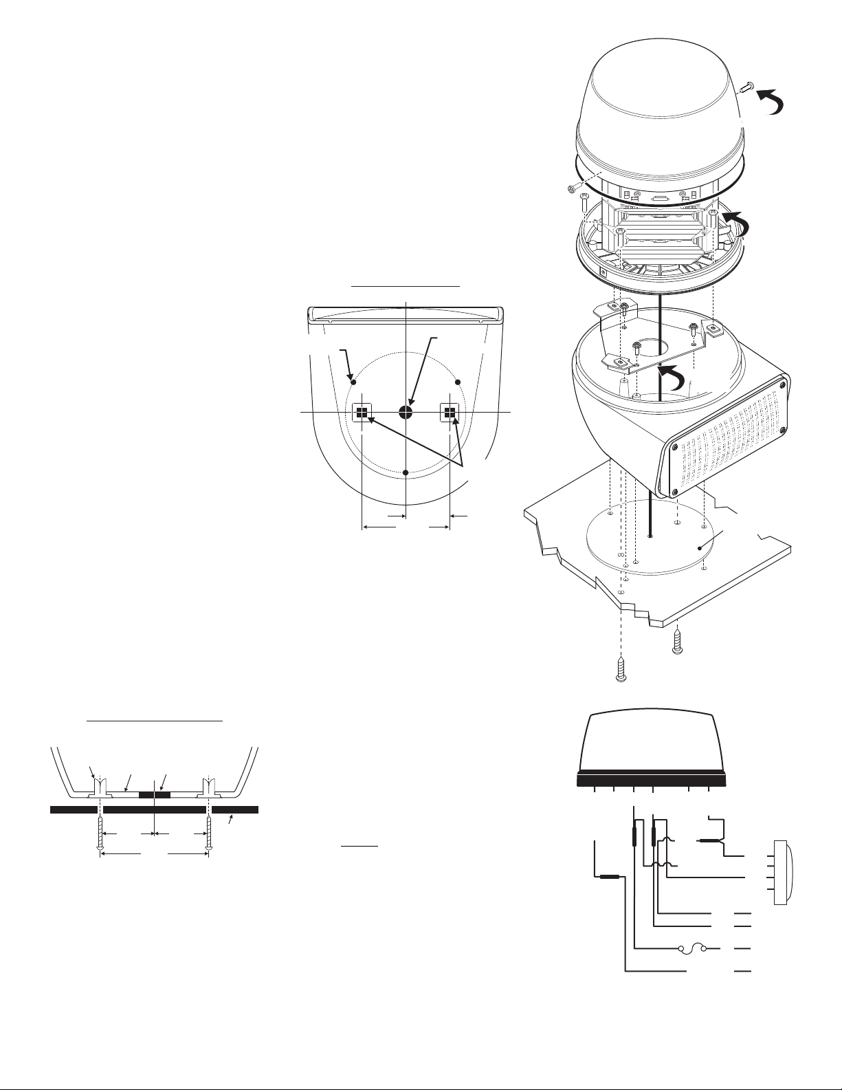
1. Remove
Dome &
Gasket
1.
1.
MOUNTING SCREWS
(Thru Hole Mounting)
MOUNTING
SURFACE
3. Remove
3. beacon's
3. mounting
3. bracket
3. Remove
3. beacon's
3. mounting
3. bracket
MOUNTING
GASKET
2. Remove
screws
and slide
beacon
out.
2.
3. Remove
beacon's
mounting
bracket
3.
3.
3.
WHITE-VIOLET N/C
WIRING
DIAGRAM
WHITE-VIOLET N/C
GREY N/C
WHITE-ORANGE
RED
BLACK
This wire is the color of the LED
BLACK
VIOLET
VIOLET
VIOLET
RED
BLACK
VIOLET
WHITE-ORANGE
L360 SERIES
700 SERIES
+12 VDC
Ground
Low Power
Cruise Light
5 AMP
FUSE
Mounting Holes
TOP VIEW / STANDARD and THRU-HOLE
1-3/4"
3.5"
THRU HOLE
MOUNTING
MOUNTING
HOLES (3)
3/8" DIA
WIRE HOLE
The Model B6MM warning light combines a Super-LED® Beacon with either a 700 Series
MOUNTING
SURFACE
FASTEX
GROMMET
BASE
WIRE
HOLE
1¾"
3½"
1¾"
Thru Hole Mounting
FRONT VIEW / CROSS SECTION
Super-LED® lighthead, a Halogen Scenelight a 700 Series LED Scenelight or an M7
lighthead for double warning in one light. It also meets the new standards set by the
NFPA. for the rear upper Zone “C” applications.
Installation:
WARNING! Since this installation will require drilling, it is absolutely necessary
to make sure that no other vehicle components could be damaged by this
process. Check both sides of the mounting surface before starting. If damage is
likely, select a different mounting location.
STANDARD MOUNTING:
1. Dismantle the unit by first removing the 2 sheet metal screws which hold the lens onto the
beacons base and remove the dome and
gasket.
2. Remove the three screws that hold the
beacon to the beacon bracket and
separate the beacon from it’s mounting
bracket.
3. Remove the screws that hold the beacon
bracket to the base and slide the bracket
up and out so you can access the
mounting holes on the bottom of the
base.
4. Position the base housing onto the
vehicle so that the lower light device is
facing directly rearward, locate the three
mounting holes drilled into the base
housing (See diagram) and mark them off
on the mounting surface of the vehicle.
5. Remove the unit and position the base
gasket onto the vehicle. Line the gasket
up with the marks you made for the
mounting screws and mark off the center wire access hole using the gasket as a template.
6. Drill the base mounting holes for the three #10 sheet metal screws and drill the center wire
access hole to 3/8 inch (Grommet wire hole as needed / Customer supplied).
7. Feed the wires out of the unit, through the mounting gasket and through the access hole
and connect them to your power source. (See wiring)
8. Attach the base to the vehicle with the 3 sheet metal screws supplied, then reassemble and
test the unit.
Operation:
Cruise Light:
Apply +12 VDC to the WHITE-ORANGE wire to turn on the cruise light. Remove the voltage from the
WHITE-ORANGE wire to restore normal operation.
Hi/Low Intensity:
Apply +12 VDC to the VIOLET wire to put the beacon into low power. Remove the voltage from the
VIOLET wire to restore normal high power operation.
THRU HOLE MOUNTING (Optional): To install the unit
using “Thru Hole Mounting”, on the mounting surface, drill
two holes sized for a ¼” sheet metal screw the distances
shown in the diagram. Be sure the unit is facing the
desired direction that it will face once installed. Insert the
customer supplied screws up through the bottom of the
base and tighten to secure.
WARNING: All customer supplied wires that connect
to the positive terminal of the battery must be sized to
supply at least 125% of the maximum operating
current and FUSED
at the battery to carry that load. DO
NOT USE CIRCUIT BREAKERS WITH THIS PRODUCT!
Page 2
Page 3

Specifications
Input Voltage:
Input Current:
Input Current:
Flash Patterns:
Low Power:
12.8 VDC ±20
L360 Beacon - 1.5 AMPS
700 Flasher - .75 AMPS
SignalAlert™ (Default)
+12V Active
9
LOWER LED / LENS COLOR
AMBER / AMBER
BLUE / BLUE
RED / RED
AMBER / CLEAR
BLUE / CLEAR
WHITE / CLEAR
RED / CLEAR
A=
B=
R=
1=
2=
3=
5=
PART NUMBER KEY:
LOWER LED / LENS COLOR
UPPER LED / LENS COLOR
01-0684139-__
UPPER LED / LENS COLOR
A=
B=
R=
1=
2=
3=
5=
G=
AMBER / AMBER
BLUE / BLUE
RED / RED
AMBER / CLEAR
BLUE / CLEAR
WHITE / CLEAR
RED / CLEAR
GRN / GRN
26-0215001-06
01-0286419410
01-0286419420
01-0286419430
01-0286419450
01-02864194A0
01-02864194B0
01-02864194R0
21-12081205-3
07-242837-000
07-263938-000
14-062216-061
38-0242422-00
15-061416-240
01-0685953NRF
01-0685953-2F
01-0685953-1F
01-0685953-3F
01-0685953N5F
01-0685953-AF
11-483144-011
01-0684139-__
01-0685953-BF
BEACON AMB/AMB FLAT MT L360 SERIES
B6MM SERIES Super-LED® L360 700 LED/
HOUSING / BASE MODEL B6R - POLISHED
BEACON RED-CLR NFPA FLAT MT L360 SERIES
BEACON RED-RED NFPA FLAT MT L360 SERIES
BRACKET / MOUNTING MECHANISM / LOWER LED
BEACON WHT-CLR FLAT MT L360 SERIES
BEACON BLU-CLR FLAT MT L360 SERIES
BEACON AMB-CLR FLAT MT L360 SERIES
BEACON BLU-BLU FLAT MT L360 SERIES
SCREW / #6 X 1 1/2" PPHSMS
SCREW / #6-32 X 3/8" PPHMS SEMS
GASKET / MOUNTING B6R SERIES
700 LINEAR TIR / AMBER-CLEAR
700 LINEAR TIR / BLUE-CLEAR
700 LINEAR TIR / WHITE-CLEAR
700 LINEAR TIR / RED-CLEAR
700 LINEAR TIR / AMBER-AMBER
700 LINEAR TIR / BLUE-BLUE
700 LINEAR TIR / RED-RED
BRACKET MOUNTING B6R MECHANISM 360° LED/
SCREW GROMMET FASTEX
TY-WRAP 6" BLACK/
13-062C40-16J
01-0685953-GF
15-101416-120
21-17060704-3
A/R
A/R
1
2
A/R
A/R
A/R
A/R
A/R
A/R
4
REF
REF
3
1
2
A/R
A/R
A/R
A/R
A/R
A/R
3
3
A/R
4
SCREW #10 X 3/4" PPHSMS SS/
SCREW GROMMET FASTEX
#6 - #8 SCREW GROMMET
BEACON GREEN/GREEN FLAT MT L360 SERIES
ITEM
PART NUMBER
DESCRIPTION
QTY
22
23
24
25
26
21
2
3
11
12
13
14
15
16
17
18
19
20
4
5
6
7
8
9
10
1
12
11
10
13
14
15
16
17
18
19
26
5
1324
6
7
8
20 21 22
25
23 24
Page 3
Page 4

Specifications
Input Voltage:
Input Current:
Input Current:
Flash Patterns:
Low Power:
12.8 VDC ±20
L360 Beacon - 1.5 AMPS
700 Flasher - .75 AMPS
SignalAlert™ (Default)
+12V Active
LOWER SCENE STYLE
Z HALOGEN SCENE
LED SCENE
=
Y=
LOWER SCENE STYLE
UPPER LED / LENS COLOR
01-0684139-__
UPPER LED / LENS COLOR
A=
B=
R=
1=
AMBER / AMBER
BLUE / BLUE
RED / RED
AMBER / CLEAR
BLUE / CLEAR
WHITE / CLEAR
RED / CLEAR
GRN / GRN
2=
3=
5=
G=
B6MM SERIES Super-LED L360/LED SCENE
HOUSING / BASE MODEL B6R - POLISHED
01-0685953-BF
01-0684139-_Y
11-483144-011
01-0685953-AF
SCREW #6 X 1 1/2" PPHSMS/
SCREW GROMMET FASTEX
BRACKET MOUNTING MECHANISM LOWER LED//
BRACKET MOUNTING B6R MECHANISM 360° LED/
01-0685953N5F
01-0685953-3F
01-0685953-1F
01-0685953-2F
01-0685953NRF
15-061416-240
38-0242422-00
14-062216-061
07-263938-000
07-242837-000
21-12081205-3
TY-WRAP 6" BLACK/
26-0215001-06
GASKET MOUNTING B6R SERIES/
SCREW #6-32 X 3/8" PPHMS SEMS/
SCREW GROMMET FASTEX
21-17060704-3
SCREW #10 X 3/4" PPHSMS SS/
15-101416-120
BEACON AMB/AMB FLAT MT L360 SERIES
BEACON BLU/BLU FLAT MT L360 SERIES
BEACON RED/RED NFPA FLAT MT L360 SERIES
BEACON AMB/CLR FLAT MT L360 SERIES
BEACON BLU/CLR FLAT MT L360 SERIES
BEACON WHT/CLR FLAT MT L360 SERIES
BEACON RED/CLR NFPA FLAT MT L360 SERIES
01-0685953-GF
ASSY / BEACON GRN/GRN FLAT MT L360 SERIES
68-1183464-3S
LENS CLEAR 7E SCENELIGHT W/ SEAL/
01-026A532-10
SUB-ASS'Y LED SCENE LT 700 NO CONNECTOR//
13-062C40-16J
SCREW GROMMET / #6/8
34-0041987-00
SNAP-IN LAMP 12V/35H
02-0383709-05
700 REFLECTOR W/O LAMP 2-WIRE NO CONN
01-0684139-_Z
B6MM SERIES Super-LED L360/HALO SCENE
11-461065-000
HOUSING LIGHT ASSY MINI MAX/
4
A/R
1
A/R
A/R
A/R
A/R
A/R
A/R
-
REF
REF
3
1
2
1
1
1
33
3
1
A/R
-
-
1
A/R
A/R
4
REF
REF
3
2
1
A/R
A/R
A/R
A/R
A/R
1
33
3
2
A/R
1
A/R
4
-
-
-
-
38-0241199-00
GASKET
ITEM
PART NUMBER
DESCRIPTION
QTY QTY
22
23
24
25
21
2
3
11
12
13
14
15
16
17
18
19
20
4
5
6
7
8
9
10
1
9
11
12
10
13
25
23
24
22
21
16
20
17
18
14
15
5
3
4
6
7
8
1
2
19
Page 4
Page 5

Specifications
Input Voltage:
Input Current / L360 Beacon:
Input Current M7 Lighthead:
Flash Patterns:
Low Power:
12.8 VDC ±20
1.5 AMPS
0.75 AMPS
SignalAlert™ (Default)
+12V Active
Upper LED / Lens Color
AMBER / AMBER
BLUE / BLUE
RED / RED
AMBER / CLEAR
BLUE / CLEAR
WHITE / CLEAR
RED / CLEAR
GREEN / GREEN
A=
B=
R=
1=
2=
3=
5=
G=
01-0686341-__
Upper LED
Lens Color
Lower LED
Lens Color
Lower LED / Lens Color
AMBER / AMBER
BLUE / BLUE
RED / RED
AMBER / CLEAR
BLUE / CLEAR
WHITE / CLEAR
RED / CLEAR
A=
B=
R=
1=
2=
3=
5=
1112
3
4
5
6
7
8
9
12
14
15
13
16
17
18
20 21 22
24
23
25 26
19
27
28
SUB ASSY M7 SYNC BLU BLU/-
A/R
A/R
1
2
A/R
A/R
A/R
A/R
A/R
A/R
1
2
REF
REF
3
1
2
A/R
BEACON AMB-AMB FLAT MT L360 SERIES
B6M7 SERIES Super-LED L360/M7 LED
HOUSING / BASE MODEL B6R - POLISHED
BEACON RED/CLR NFPA FLAT MT L360 SERIES
BEACON RED-RED NFPA FLAT MT L360 SERIES
BRACKET MOUNTING LED B6R/
GASKET DIE CUT PSA M7/
BEACON WHT-CLR FLAT MT L360 SERIES
BEACON BLU-CLR FLAT MT L360 SERIES
BEACON AMB-CLR FLAT MT L360 SERIES
BEACON BLU-BLU FLAT MT L360 SERIES
SCREW #8 X 1" PPHSMS/
SUB ASSY M7 SYNC AMB AMB/-
SCREW #6-32 X 3/8" PPHMS SEMS/
GASKET MOUNTING B6R SERIES/
BRACKET M G B6MM MECHANISM 360° LED/T
SCREW GROMMET FASTEX
TY-WRAP 6" BLACK/
02-036A796-B0
02-036A796-A0
38-0143750-00
26-0215001-06
21-12081205-3
07-242837-000
07-263938-000
14-062216-061
38-0242422-00
15-081416-160
01-0685953NRF
01-0685953-2F
01-0685953-1F
01-0685953-3F
01-0685953N5F
01-0685953-AF
11-483144-011
01-0686341-__
01-0685953-BF
02-036A796-50
02-036A796-20
02-036A796-10
02-036A796-R0
02-036A796-30
07-743879-000
13-062C40-16J
01-0685953-GF
15-101416-120
21-17060704-3
A/R
A/R
A/R
1
2
3
3
A/R
A/R
A/R
SUB ASSY M7 SYNC RED RED/-
SUB ASSY M7 SYNC WHT CLR/-
M7 TO B6R-B6T ADAPTOR PLATE
SCREW GROMMET #6/8
BEACON GRN GRN FLAT MT L360 SERIES-
SCREW #10 X 3/4" PPHSMS SS/
SCREW GROMMET FASTEX
SUB ASSY / M7 SYNC RED-CLR
SUB ASSY M7 SYNC BLU-CLR/
SUB ASSY M7 SYNC AMB-CLR/
ITEM
PART NUMBER
DESCRIPTION
QTY
22
23
24
25
26
27
28
21
2
3
11
12
13
14
15
16
17
18
19
20
4
5
6
7
8
9
10
1
10
Page 5
 Loading...