

Page 1
®
ENGINEERING COMPANY INC.
51 Winthrop Road
Chester, Connecticut 06412-0684
Phone: (860) 526-9504
Installation Guide:
Alpha™ Series
Remote Siren Amplifier
Fax: (860) 526-4078
Internet: www.whelen.com
Sales e-mail: autosale@whelen.com
Canadian Sales e-mail: autocan@whelen.com
Customer Service e-mail: custserv@whelen.com
DANGER! Sirens produces extremely loud emergency warning tones! Exposure to these
tones without proper and adequate hearing protection, could cause ear damage and/or hearing
loss! The Occupational Safety & Health Administration (www.osha.gov) provides information
necessary to determine safe exposure times in Occupational Noise Exposure Section 1910.95.
Until you have determined the safe exposure times for your specific application, operators and
anyone else in the immediate vicinity should be required to wear an approved hearing protection
device. FAILURE TO FOLLOW THIS RECOMMENDATION COULD CAUSE HEARING LOSS!
Safety First
This document provides all the necessary information to allow your Whelen product to be properly and safely installed.
Before beginning the installation and/or operation of your new product, the installation technician and operator must
read this manual completely. Important information is contained herein that could prevent serious injury or damage.
• Proper installation of this product requires the installer to have a good understanding of automotive electronics,
systems and procedures.
• If mounting this product requires drilling holes, the installer MUST be sure that no vehicle components or other
vital parts could be damaged by the drilling process. Check both sides of the mounting surface before drilling
begins. Also de-burr any holes and remove any metal shards or remnants. Install grommets into all wire
passage holes.
• If this manual states that this product may be mounted with suction cups, magnets, tape or Velcro®, clean the
mounting surface with a 50/50 mix of isopropyl alcohol and water and dry thoroughly.
• Do not install this product or route any wires in the deployment area of your air bag. Equipment mounted or
located in the air bag deployment area will damage or reduce the effectiveness of the air bag, or become a
projectile that could cause serious personal injury or death. Refer to your vehicle owner’s manual for the air bag
deployment area. The User/Installer assumes full responsibility to determine proper mounting location, based
on providing ultimate safety to all passengers inside the vehicle.
• For this product to operate at optimum efficiency, a good electrical connection to chassis ground must be
made. The recommended procedure requires the product ground wire to be connected directly to the NEGATIVE
(-) battery post.
• If this product uses a remote device to activate or control this product, make sure this control is located in an
area that allows both the vehicle and the control to be operated safely in any driving condition. DO NOT
ATTEMPT TO ACTIVATE OR CONTROL THIS DEVICE IN A HAZARDOUS DRIVING SITUATION.
• It is recommended that these instructions be stored in a safe place and
referred to when performing maintenance and/or reinstallation of this
product.
• FAILURE TO FOLLOW THESE SAFETY PRECAUTIONS AND
INSTRUCTIONS COULD RESULT IN DAMAGE TO THE PRODUCT OR
VEHICLE AND/OR SERIOUS INJURY TO YOU AND YOUR PASSENGERS!
ACTIVATION OF THIS
SIREN MAY DAMAGE
UNPROTECTED EARS!
CAUTION
Loud siren noise can cause
hearing damage and/or loss.
Wear
Refer to OSHA Section 1910.95 prior
Protection!
to putting ANY siren into service!
Automotive: Sirens/Switches
For warranty information regarding this product, visit www.whelen.com/warranty
©1996 Whelen Engineering Company Inc.
Form No.13093F (050608)
Page 1
Page 2
Mounting the Alpha™ Series Remote Siren Amplifier
1. Locate a suitable mounting location for the Alpha. The vertical wall between the trunk and the passenger compartment is
often a good choice and is the method discussed in this manual.
2. Be sure that the remote amplifier fits properly and does not interfere with any parts of the trunk lid or seat back.
3. Position the remote amplifier on the proposed mounting location. Using an awl or other suitable tool, scribe the mounting
surface where the mounting holes are to be drilled.
CAUTION! As mounting the Alpha will require drilling, it is absolutely necessary to make sure that no other vehicle
components could be damaged by the drilling process. If any vehicle component could suffer any potential harm,
select a different mounting location.
4. Carefully drill the mounting holes using a drill bit sized for a #8 sheet metal screw.
5. Using the supplied #8 x 5/8” sheet metal screws, secure the remote amplifier to the vertical trunk wall.
Wiring the Alpha Series Siren Amplifier (6-position connector)
Connecting to Power:
1. Extend the RED and BLACK wires through the firewall and into the engine compartment.
2. Follow the factory wiring harness towards your vehicle’s battery.
WARNING! All customer supplied wires that connect to the positive terminal of the battery must be sized to supply at
least 125% of the maximum operating current and FUSED
BREAKERS WITH THIS PRODUCT!
3. Connect the RED wire to one end of a user supplied fuse block. Do not connect this unit to the battery yet!
4. Connect the BLACK wire directly to the NEGATIVE battery terminal.
Connecting to Your Speaker (100 watt):
1. Route the YELLOW and BROWN wires along the factory wiring harness towards your speaker.
2. Connect the YELLOW wire to the POSITIVE (+) terminal on the speaker.
3. Connect the BROWN wire to the NEGATIVE (-) terminal on the speaker.
Wiring the Alpha Series Siren Amplifier (9-position connector)
at the battery to carry that load. DO NOT USE CIRCUIT
The Alpha series siren configuration and functionality are determined by the user supplied switches connected to the Alpha
amplifier. A brief explanation of each of the function wires of the 9-position connector will serve as a guide to help determine the
best configuration for your specific needs:
RED
Provides current for customer supplied switch operation (0.5 amp max.).
WHITE/GREEN
Connects to a user supplied horn transfer switch
(Fig. 1) enabling the vehicle horn ring to control
the siren.
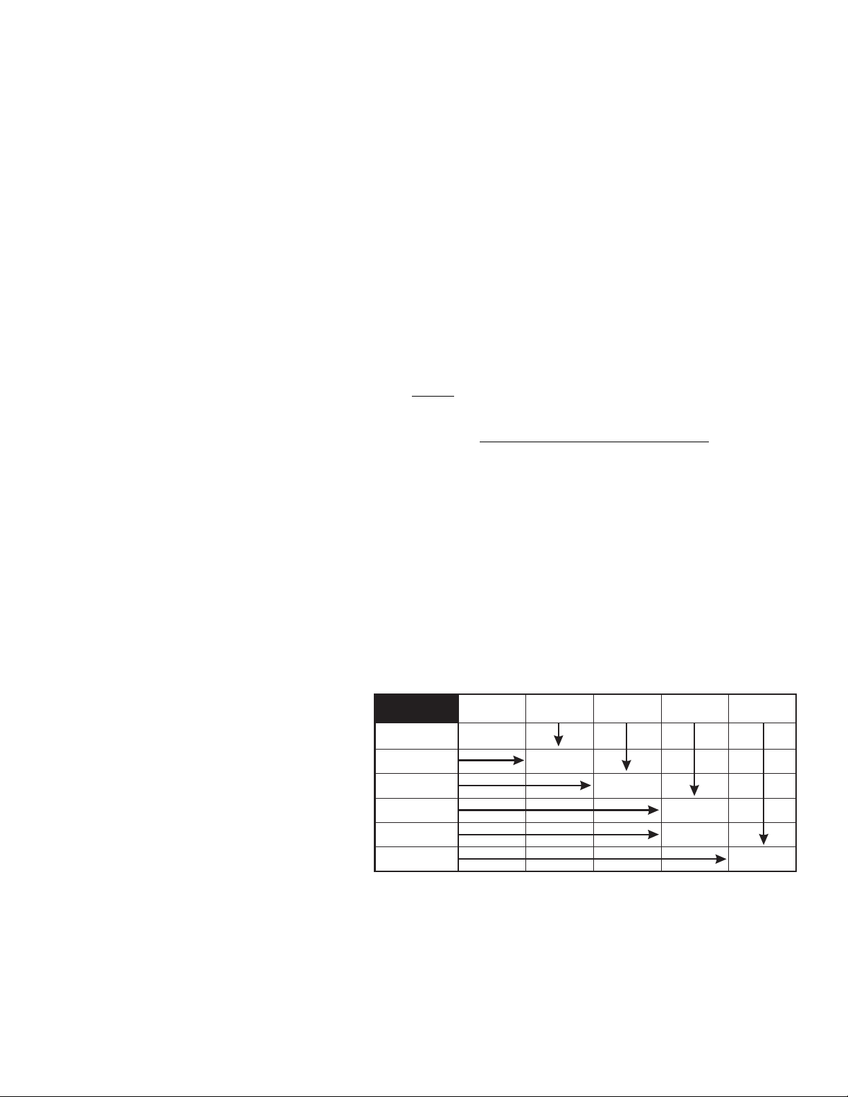
TONE CONTROL
TABLE
WHITE/BROWN
+ Battery
Terminal
WAIL
+ Battery
Terminal
+ Battery
Terminal
+ Battery
Terminal
+ Battery
Terminal
WHITE/BROWN
Activates the Wail tone.
WHITE/RED
Activates the Yelp tone.
NOTE: Connecting both the WHITE/BROWN
and WHITE/RED wires activates the Piercer™
tone.
WHITE/RED
WHITE/BROWN
& WHITE/RED
WHITE/ORANGE
WHITE/GREEN
WHITE/YELLOW
YELP
PIERCER
or Hi/Low
HANDS FREE
MODE
EMABLED
HANDS FREE
MODE
ACTIVATION
AIRHORN
WHITE/ORANGE
Enables Hands-Free operation.
WHITE/YELLOW
Activates Air Horn tone.
The installation of your Alpha series siren amplifier will be complete after the fuse block wire is connected to the POSITIVE
(+) terminal of the battery. After this connection has been made, visually inspect the fuses at the back of the amplifier and at the
battery. If either of these fuses is blown, carefully inspect all of the circuit wires and make sure they are wired correctly. Replace
the blown fuses with ones of an identical amp rating as the original. If these fuses blow after installation or activation, contact
Whelen Engineering Technical Support.
Page 2
Page 3

Connecting to your Horn Relay:
1. Locate your vehicle’s horn relay. Now locate the wire that connects the vehicle horn to the horn relay and cut this wire.
2. Extend each end of the cut wire (using a minimum 16 gauge wire) to a user supplied SPDT horn transfer switch.
3. Connect the wire coming from the horn relay to the switch “wiper” as shown below.
4. Connect the wire coming from the horn to one side of the switch as shown below.
5. Connect the WHITE/GREEN wire from the 9-position connector to the other side of the switch as shown below.
ACTIVATION OF THIS
SIREN MAY DAMAGE
UNPROTECTED EARS!
CAUTION
Loud siren noise can cause
hearing damage and/or loss.
Wear
Refer to OSHA Section 1910.95 prior
to putting ANY siren into service!
Protection!
SPEAKER
CHASSIS
GROUND
+
-
-
BATTERY
+
7.5 AMP FUSE (24V installation)
10 AMP FUSE (12V installation)
(CUSTOMER SUPPLIED)
ALPHA SIREN AMPLIFIER
YEL
BRN
BLK
RED
6 Position
Connector
9 Position
Connector
HORN TRANSFER SWITCH
(CUSTOMER SUPPLIED)
WHT/GRN (Horn Ring)
RED (Aux. Power)
WHT/BRN (Wail Tone)
WHT/RED (Yelp Tone)
WHT/ORG (Hands Free)
WHT/YEL (Air Horn)
CUSTOMER SUPPLIED SWITCHES
Alpha Siren Specifications
12 Volt 24 Volt
INPUT VOLTAGE 13.5 VDC ± 20% 26.5 VDC + 20%
INPUT CURRENT (OFF) 0 mA 0 mA
INPUT CURRENT (STANDBY) 175 mA (TYP.) 250 mA (TYP.)
INPUT CURRENT (SIREN) 8 Amps (TYP.) 4 Amps (TYP.)
OUTPUT VOLTAGE 34 V RMS (MAX.) 34 V RMS (MAX.)
SPEAKER (1) 11 ohm (1) 11 ohm
OUTPUT POWER 105 WATTS (MAX.) 105 WATTS (MAX.)
H/R VOLTAGE INPUT VOLTAGE INPUT VOLTAGE
or GROUND or GROUND
H/R CURRENT 15 mA (TYP.) 15 mA (TYP.)
OPERATING TEMP. -30° C. to +60°C. -30° C. to +60°C.
OPERATING HUMIDITY 95% Non-Condensing 95% Non-Condensing
@ 15 VDC @ 30 VDC
SPDT
TO
HORN
RELAY
VEHICLE
HORN
CUT
HERE
Hands-Free Siren Activation (Default)...
The Alpha siren amplifier, when installed according to the above wiring diagram, offers the ability to activate siren tones using the
vehicle’s steering wheel horn ring. After the horn transfer switch has been set to siren operation, the hands-free mode is enabled
when switch 3 is closed. After hands-free mode is enabled, pressing the horn ring button will start the Wail siren tone. A second
press of the horn ring button will change the siren tone from Wail to Yelp. A third press will change the siren tone from Yelp to
Piercer™. The siren tones will continue to cycle from Wail to Yelp to Piercer with each subsequent press of the horn ring button.
Two, rapid presses on the horn ring button ends hands-free siren tone generation until the horn ring button is pressed again. At that
time the cycle is repeated.
To exit the hands-free mode, end current siren tone with two, rapid horn ring presses, turn off switch 3 and return the horn transfer
switch to its normal operating position. Normal vehicle horn operation is then restored.
Manual Siren Activation (Optional)...
The Alpha siren amplifier, when installed according to the wiring diagram on page 4, offers manual siren activation using the
vehicle’s steering wheel horn ring as a momentary switch. After the horn transfer switch has been set to siren operation, the horn
ring button will now activate the manual siren tone. The default manual siren tone “ramps up” to a predetermined level and
continues at that level until the manual switch is released. When the switch is released, the tone is immediately terminated.
Page 3
Page 4

Dip Switch Functions Explained...
Some of the default functions of the Alpha™ siren amplifier can be customized (via Dip Switches) to suit the needs of the
operator. In the default factory configuration, each dip switch is in the Down (ON) position. The following section will explain dip
switch functionality in both the ON and OFF position:
Dip Switch #1 Dip Switch #2
Down (Default)Ton e 3 & Hands-Free 3rd tone are Enabled Down (Default)Tone 3 & Hands-Free 3rd tone are Piercer™
Up (Optional)Ton e 3 & Hands-Free 3rd tone are Disabled Up (Optional)Ton e 3 & Hands-Free 3rd tone are Hi/Low
Dip Switch #3 Dip Switch #4
Down (Default)Ton e 3 is the override tone for Yelp Down (Default)Wail has normal Yelp override
Up (Optional)Airhorn is the override tone for Yelp Up (Optional)Wail has 10 second override for Yelp
Dip Switch #5
Down (Default)Manual tone ramps up to a pre-determined level and, upon release, terminates
Up (Optional)Manual tone ramps up to a pre-determined level and, upon release, ramps down and terminates
Dip Switches #6, #7 & #8
NOTE: Unlike dip switches #1 through #5, where each dip switch functions independently of the others, dip switches #6, #7 and
#8 are used in conjunction with each other to achieve a specific function.
Dip
Dip
Switch
7
ON
Dip
Switch
Description of system functionality
8
Default Configuration
ON
Switch
6
ON
ON
OFF
OFF
OFF
ON
ON
Yelp has priority over all tones (except Airhorn). Hands-Free is not effected in this setting.
ON
Manual siren operation replaces Hands-Free operation. The vehicle’s horn ring now acts
ON
as the manual siren tone activation button. Hands-Free siren functions are not available.
Yelp has priority over all tones(except Air Horn). Manual siren operation replaces Hands-
OFF
Free operation. The vehicle’s horn ring now acts as the manual siren tone activation button.
Hands-Free siren functions are not available.
System emulates WS610 siren. If the Alpha is to be configured for WS610 emulation, it must
OFF
be wired as shown below.
*
OFF
ON
OFF
OFF
ON
Wail has priority over all tones (except Airhorn). Hands-Free is not effected in this setting.
ON = DOWN OFF = UP
*In this configuration, a Wail tone is generated by closing the switch (SW1) connected to the WHT/BRN wire. Pressing the
momentary switch (MSW1) connected to the WHT/RED wire changes the tone to Yelp. Subsequent presses of the momentary
switch will cause the tones to alternate between Wail and Yelp. Opening SW1 ends siren tone generation. Pressing the momentary switch, while SW1 is open, will cause a Yelp tone to be generated for as long as the momentary switch is pressed.
If a simulated Airhorn tone is desired, connect a normally open momentary switch to the WHT/YEL wire. When +12VDC is
applied, the desired Airhorn tone will be generated.
ACTIVATION OF THIS
SIREN MAY DAMAGE
UNPROTECTED EARS!
CAUTION
Loud siren noise can cause
hearing damage and/or loss.
Wear
Refer to OSHA Section 1910.95 prior
to putting ANY siren into service!
Protection!
SPEAKER
CHASSIS
GROUND
+
-
-
BATTERY
10 AMP FUSE (12V installation)
7.5 AMP FUSE (24V installation)
+
(CUSTOMER SUPPLIED)
MSW1 - Single Pole / Momentary Switch
ALPHA
SIREN AMPLIFIER
(WS610 Emulation Mode)
6 Position
9 Position
Connector
Connector
YEL
BRN
BLK
RED
(Customer Supplied)
Single Pole / Single Throw Switch
RED (Aux. Power)
WHT/BRN (Wail Tone)
WHT/RED (Yelp Override)
WHT/ORG
WHT/GRN
WHT/YEL
(Customer Supplied)
*NOTE: Applying +VDC
to this wire will generate a
Simulated Air Horn Siren Tone
SW1
X No Connection
X No Connection
X No Connection*
Page 4
 Loading...