

Page 1
®
ENGINEERING COMPANY INC.
51 Winthrop Road
Chester, Connecticut 06412-0684
Alpha™ Series Siren Amplifier
Installation Guide:
Phone: (860) 526-9504
Fax: (860) 526-4078
Internet: www.whelen.com
Sales e-mail: autosale@whelen.com
Canadian Sales e-mail: autocan@whelen.com
Customer Service e-mail: custserv@whelen.com
DANGER! Sirens produces extremely loud emergency warning tones! Exposure to these
tones without proper and adequate hearing protection, could cause ear damage and/or hearing
loss! The Occupational Safety & Health Administration (www.osha.gov) provides information
necessary to determine safe exposure times in Occupational Noise Exposure Section 1910.95.
Until you have determined the safe exposure times for your specific application, operators and
anyone else in the immediate vicinity should be required to wear an approved hearing protection
device. FAILURE TO FOLLOW THIS RECOMMENDATION COULD CAUSE HEARING LOSS!
Safety First
This document provides all the necessary information to allow your Whelen product to be properly and safely installed.
Before beginning the installation and/or operation of your new product, the installation technician and operator must
read this manual completely. Important information is contained herein that could prevent serious injury or damage.
• Proper installation of this product requires the installer to have a good understanding of automotive electronics,
systems and procedures.
• If mounting this product requires drilling holes, the installer MUST be sure that no vehicle components or other
vital parts could be damaged by the drilling process. Check both sides of the mounting surface before drilling
begins. Also de-burr any holes and remove any metal shards or remnants. Install grommets into all wire
passage holes.
• If this manual states that this product may be mounted with suction cups, magnets, tape or Velcro®, clean the
mounting surface with a 50/50 mix of isopropyl alcohol and water and dry thoroughly.
• Do not install this product or route any wires in the deployment area of your air bag. Equipment mounted or
located in the air bag deployment area will damage or reduce the effectiveness of the air bag, or become a
projectile that could cause serious personal injury or death. Refer to your vehicle owner’s manual for the air bag
deployment area. The User/Installer assumes full responsibility to determine proper mounting location, based
on providing ultimate safety to all passengers inside the vehicle.
• For this product to operate at optimum efficiency, a good electrical connection to chassis ground must be
made. The recommended procedure requires the product ground wire to be connected directly to the NEGATIVE
(-) battery post.
• If this product uses a remote device to activate or control this product, make sure this control is located in an
area that allows both the vehicle and the control to be operated safely in any driving condition. DO NOT
ATTEMPT TO ACTIVATE OR CONTROL THIS DEVICE IN A HAZARDOUS DRIVING SITUATION.
• It is recommended that these instructions be stored in a safe place and
referred to when performing maintenance and/or reinstallation of this
product.
• FAILURE TO FOLLOW THESE SAFETY PRECAUTIONS AND
INSTRUCTIONS COULD RESULT IN DAMAGE TO THE PRODUCT OR
VEHICLE AND/OR SERIOUS INJURY TO YOU AND YOUR PASSENGERS!
ACTIVATION OF THIS
SIREN MAY DAMAGE
UNPROTECTED EARS!
CAUTION
Loud siren noise can cause
hearing damage and/or loss.
Wear
Refer to OSHA Section 1910.95 prior
Protection!
to putting ANY siren into service!
Automotive: Sirens/Switches
For warranty information regarding this product, visit www.whelen.com/warranty
©1996 Whelen Engineering Company Inc.
Form No.13086D (050608)
Page 1
Page 2
Mounting the Alpha
TM
Series Siren Amplifier:
The Alpha siren, although technologically advanced, is simple to
install. An aftermarket center console is recommended for the
mounting location of the siren. This not only allows the driver to
reach the controls easily, but also keeps the unit safely out of
the path of the vehicle’s SRS air-bag. Follow the console
manufacturer’s instructions for mounting information. If a
console-type mount is not possible, the siren includes a bail
strap mounting kit for over or under dash mounting.
The following steps will guide you through the bail strap
installation process:
1. Select a mounting location for the Alpha siren, either on top
of, or below your vehicle’s dashboard.
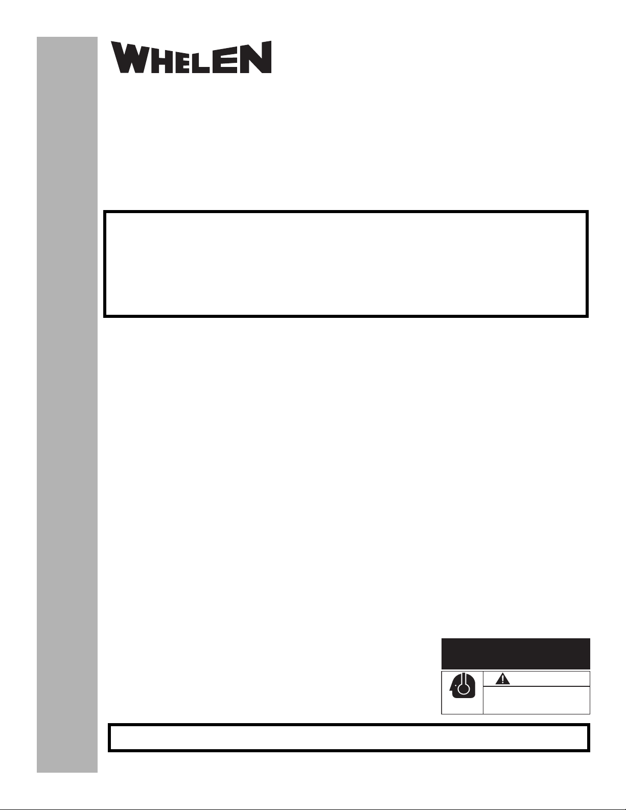
2. Using the bail strap as a guide, drill two 1/8” holes and
secure the bail strap to the dashboard with two #10 x 1”
Phillips pan head sheet metal screws (user supplied). Refer
to Figure 1.
Fig. 1
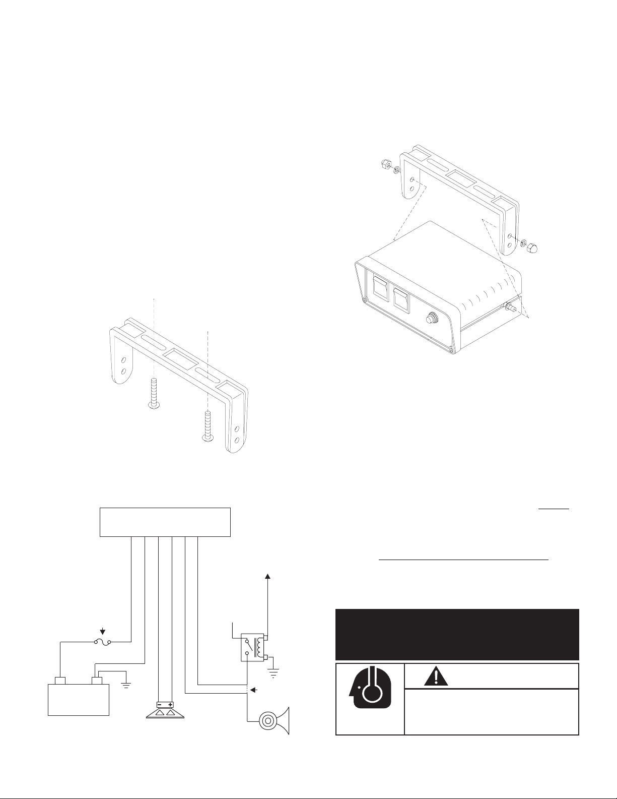
4. Insert the Alpha siren amplifier into the bail strap, as shown
in Figure 2. Please note that it will be necessary to spread
the bail strap arms slightly apart to accept the Alpha’s
carriage bolts into their mounting holes.
Fig. 2
5. Place a lock washer and an acorn nut on each carriage bolt
and tighten with a 3/8” wrench. Do not over-tighten!
3. Slide the carriage bolts into the middle of the mounting
tracks on the siren amplifier and fit an external-tooth lock
washer onto each of the carriage bolts.
Alpha™
(+)
12VDC
Battery
6 POSITION INPUT CONNECTOR
10 AMP FUSE
(CUSTOMER
SUPPLIED)
(-)
CHASSIS
GROUND
BLACK
RED
SPEAKER #1
BROWN
11 OHM
WHITE
GREY
ORANGE
+12V
HORN
RELAY
TO
HORN
RING
CUT
HERE
Wiring the Alpha
TM
Series Siren Amplifier
Connecting to power:
1. Extend the RED and BLACK wires through the firewall and
into the engine compartment.
2. Follow factory wiring harness towards the vehicle’s battery.
WARNING! All customer supplied wires that connect to the
positive terminal of the battery must be sized to supply at
least 125% of the maximum operating current and FUSED
the battery to carry that load. DO NOT USE CIRCUIT BREAKERS WITH THIS PRODUCT!
3. Connect the RED wire to one end of a user supplied, 10 amp
fuse block. Do not connect this unit to the battery yet!
4. Connect the BLACK wire directly to the NEGATIVE battery
terminal.
ACTIVATION OF THIS
SIREN MAY DAMAGE
UNPROTECTED EARS!
CAUTION
Loud siren noise can cause
hearing damage and/or loss.
Refer to OSHA Section 1910.95 prior
to putting ANY siren into service!
HORN
VEHICLE
Wear
Protection!
at
Page 2
Page 3

Connecting to your Horn Relay:
1. Route the WHITE and GREY wires along the factory wire
harness and through the firewall at the same point as the
RED and BLACK wires.
2. Locate your vehicle’s horn relay and route the WHITE and
GREY wires to this. If possible, follow the factory wire harness to this relay.
3. Locate the wire that connects the vehicle horn to the horn
relay. Cut this wire.
4. Connect the WHITE wire to the wire coming from the horn
relay.
5. Connect the GREY wire to the wire coming from the horn.
Connecting to your Speaker (100 watt):
1. Route the ORANGE and BROWN wires along the factory
wiring harness towards your speaker.
2. Connect the ORANGE wire to the POSITIVE (+)
terminal on the speaker.
3. Connect the BROWN wire to the NEGATIVE (-)
terminal on the speaker.
The installation of your Alpha Series siren amplifier will be complete after the fuse block wire is connected to the POSITIVE (+)
terminal of the battery. After this connection has been made,
visually inspect the fuses at the back of the amplifier and at the
battery. If either of these fuses is blown, carefully inspect all of
the circuit wires and make sure they are wired correctly.
Replace the blown fuses with ones of an identical amp rating
as the original. If these fuses blow after installation or activation, contact Whelen Engineering Technical Support.
AIRHORN
SW3
TM
SERIES
®
ON
SW1
POWER FUNCTION
SW2
TONE 1
HANDSFREE
TONE 2
ALPHA
Operating the Alpha Series Siren Amplifier:
Power Switch - This switch has two positions:
Down (Alpha
the Off position, the siren will not function. When the switch is in
the On position the siren is functional and may be activated at
the operator’s discretion.
NOTE: If the Alpha
cuit, the vehicle horn is disabled when the Alpha
is in the ON position.
Airhorn Button - When the Airhorn button is pressed, a simu-
lated “air horn” siren tone will be generated by your vehicle’s
loudspeaker. This tone is continuous until the Airhorn button is
released.
Function Switch - The Function Switch controls the siren func-
tions of the Alpha. There are 3 positions that may be selected.
Each position and it’s function is outlined below:
Tone 1 (WAIL) - When the function switch is in the Tone 1
- Off) and Up (Alpha - On). When this switch is in
is connected to the vehicle’s horn ring cir-
power switch
position, a steady, rise and fall tone is produced (“Wail”). A single
“tap” on the vehicle’s steering wheel horn button (if the vehicle’s
horn has been wired to the Alpha), changes the siren tone to a
“Yelp” pattern (a fast, rise and fall tone). A second “tap”, and the
siren returns to a “Wail” tone.
HF (Hands-Free Operation) - When the function switch is in the
Hands-Free position, the siren functions of the Alpha
are placed
in a stand-by mode. Siren tones are activated by a single “tap”
on the vehicle’s steering wheel horn button (if the vehicle’s horn
has been wired to the Alpha). The first tap produces a Wail tone
(a steady, rise and fall tone). A second tap produces a Yelp tone
(a fast, rise and fall tone). A third tap produces a Piercer™ tone
(an extremely fast, rise and fall tone). The next tap returns the
siren to a Wail tone and the cycle repeats itself. Two quick, successive taps stop
the siren.
Tone 2 (YELP) - When the function switch is in the Tone 2 position, a fast, rise and fall tone is produced (Yelp). A single tap on
the vehicle’s steering wheel horn button (if the vehicle’s horn has
been wired to the Alpha), changes the siren tone to a Piercer
TM
pattern (an extremely fast, rise and fall tone). With a second tap,
it will return to Yelp.
ALPHA SIREN SPECIFICATIONS
INPUT VOLTAGE . . . . . . . . . . . . 13.5 VDC ± 20%
INPUT CURRENT (OFF) . . . . . . 0 mA
INPUT CURRENT (STANDBY) . 10 mA (TYP.)
INPUT CURRENT (SIREN). . . . . 8 Amps (TYP.)
OU T PU T V O LTA G E . . . . . . . . . . 34 V RMS (MAX.)
SPEAKER . . . . . . . . . . . . . . . . . . (1) 11 ohm
OUTPUT POWER @ 15 VDC. . . 105 WATTS (MAX.)
H/R VOLTAGE . . . . . . . . . . . . . . INPUT VOLTAGE or
GROUND
H/R CURRENT . . . . . . . . . . . . . . 15 mA (TYP.)
OPERATING TEMP. . . . . . . . . . . -30° C. to +60° C.
OPERATING HUMIDITY . . . . . . . 95% NON-CONDENSING
Dip Switch Functions:
Some of the default functions of the Alpha siren amplifier can be
customized (via dip switches) to suit the needs of the operator.
In the default factory configuration, each dip switch is in the
down (ON) position. The following section will explain dip switch
functionality in both the ON and OFF position:
Down= On (Closed) Up = Off (Open)
Dip Switch #1 Down = 3rd Tone is Active
Up = 3rd Tone is Off
Dip Switch #2 Down = 3rd Tone is Piercer™
Up = 3rd Tone is Hi/Low
Dip Switch #3 Down = Piercer Override for Yelp
Up = Airhorn Override for Yelp
Dip Switch #4 Down = Wail has Normal Yelp Override
Up = Wail has 10 second Yelp Override
Dip Switch #5 Down = Manual Stop
Up = Manual Coast
Dip Switch #6 Down = Hands Free position is Hands-Free
Up = Hands Free Position is Manual
Dip Switch #7 Down (With Switch 8 Down) =Tone 2 is Yelp
Down (With Switch 8 Up) =Tone 2 is Hi/Low
Dip Switch #8 Up (With Switch 7 Down) =Tone 2 is Hi/Low
Up (With Switch 7 Up) =Tone 2 is Manual
”
Page 3
 Loading...