

Page 1

®
ENGINEERING COMPANY INC.
51 Winthrop Road
Chester, Connecticut 06412-0684
Installati on Guide:
Edge® 9M Lightbar
Phone: (860) 526-9504
Fax: (860) 526-4078
Internet: www.whelen.com
Sales e-mail: autosale@whelen.com
Canadian Sales e-mai l: auto can@whelen.com
Customer Service e-mail: custserv@whelen.com
Safety First
This document provid es all the nec es sa ry in form at ion to allow your Whelen prod uc t to b e pro perl y a nd s afe ly ins tal le d.
Before beginning the installation and/or operation of your new product, the installation technician and operator must
read this manual completely. Important information is contained herein that could prevent serious injury or damage.
• Proper installation of this product requires the installer to have a good understanding of automotive electronics,
systems and proced ur es.
• If mounting this product requires drilling holes, the installer MUST be sure that no vehicle components or other
vital parts could be damaged by the drilling process. Check both sid es of the mo unting sur f ace bef ore drilling
begins. Also de-burr any holes and remove any metal shards or remnants. Install grommets into all wire
passage holes.
• If this manual states that this product may be mounted with suction cups, magnets, tape or Velcro®, clean the
mounting surface with a 50/50 mix of isopropyl alco hol and wa te r and dry thoroughly.
• Do not install this product or route any wires in the deployment area of your air bag. Equipment mounted or
located in the air bag deployment area will damage or reduce the effectiveness of the air bag, or become a
projectile that could cause serious personal injury or death. Refer to your vehicle owner’s manual for the air bag
deployment area. The User/Installer assumes full responsibility to deter m ine pr oper mounting location, based
on providing ultimate safet y t o al l passenge rs ins id e the vehicle.
• For this product to operate at optim u m ef f icie ncy, a good electrical connec tion t o chassis ground must be
made. The recommended procedure requires the product ground wire to be connected directly to the NEGATIVE
(-) battery post.
• If this product uses a rem ote d evice to activate or control th is product, make sure that th is control is located in
an area that allows both the vehicl e a nd th e control to be operated safely in any dr i vi ng co ndi tion.
• Do not attempt to activate or con trol this device in a hazardous driving si tu at io n.
• This product contains either strobe light(s), halogen light(s), high-intensity LEDs or a com bination of these
lights. Do not stare directly into these lights. Momentary blindness and/or eye damage could result.
• Use only soap and water to clean the outer lens. Use of other chemicals could result in premature lens cracking
(crazing) and discoloration. Lenses in this cond ition hav e sign ificantly reduced effectiveness and should be
replaced immediately. Inspect and operate this product regularly to confirm its proper operation and mountin g
condition. Do not use a pre ss u re w asher to clean this product.
• It is recommended tha t th ese instructions be stored i n a safe place and referred t o w hen performing
maintenance and/or reinstallation of this product.
• FAILURE TO FOLLOW THESE SAFETY PRECAUTIONS AND INSTR UCTIONS COUL D RESULT IN DAMAGE TO
THE PRODUCT OR VEHICLE AND/OR SERIOUS INJURY TO YOU AND YOUR PASSENGERS!
Automotive: Lightbars
For warranty information regarding this product, visit www.whelen.com/warranty
©2002 Whelen Engineering Company Inc.
Form No.13657M (061410)
Page 1
Page 2
IMPORTANT! The lightbar should be located a minimum of
16" from any radio antennas!
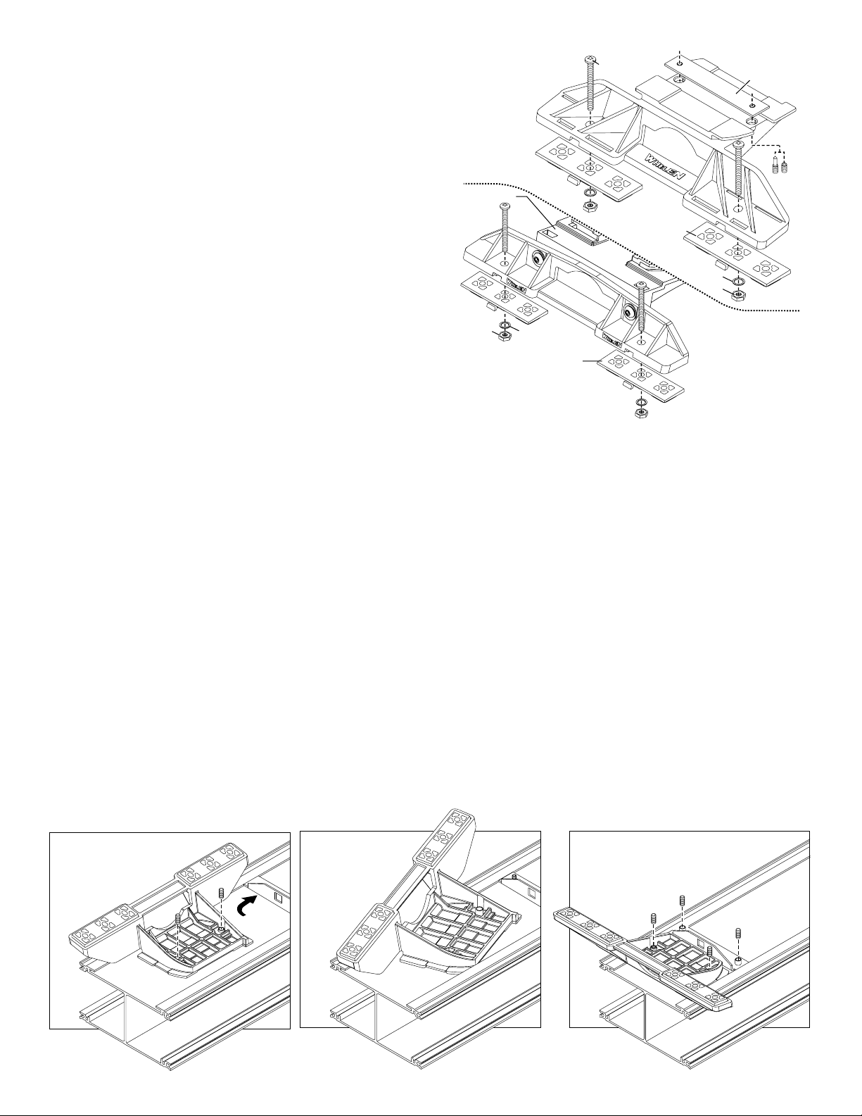
Permanent Mounting:
1. Locate the mounting foot and locking plate included with your
lightbar. If not already present, install the locking plate onto the
mounting foot. When properly positioned, this plate is centered from
side to side on the mounting foot.
2. Flip the lightbar upside-down to expose the bottom of the extrusion
and place the mounting foot onto the extrusion.
3. Rotate the mounting foot 90° in a counter-clockwise direction. Make
sure that the edges of the mounting foot swing into position under the
extrusion mounting lip.
4. Repeat this procedure for the remaining mounting foot and return the
lightbar to its right side-up position.
5. Position the lightbar onto the vehicle roof in the desired mounting
location. One often selected location is directly above the B-pillars.
This area is the strongest part of the roof. Refer to your lightbar
manual for cable exit location, to be sure that the lightbar is facing the
proper direction.
6. Adjust the two mounting feet outwards so that they are as close to
the edge of the roof as possible. Make s ure that both mounting feet
are in full contact with the roof. Be sure that there is no less than 1/2”
clearance between the roof and the lightbar at their closest point.
When the mounting feet are in their proper position, lightly tighten the
locking plate allen head set screws.
7. Turn the lightbar upside down and firmly tighten all of the set screws
from step 6 (2 or 4 per side).
8. On the adjustable foot, use the hole in the pad as a guide to drill the
two holes into the mounting foot at the locations shown.
Standard
Mounting
Bolt
Bolt
Locking
Plate
Foot
Mounting
Foot
Base
Nut
Washer
Mounting
Pad
9. Place the lightbar in its final mounting position on the vehicle, mark
the mounting hole locations off onto the mounting surface, remove
the lightbar and drill the mounting holes.
10. Place the lightbar back onto the vehicle lined up with the mounting
holes and secure the mounting feet to the vehicle with the supplied
hardware.
Mounting
Pad
Washer
Nut
Adjustable
Mounting
Foot
Strap Mounting:
1. Locate the mounting foot, anchor plate and locking plate included with
your lightbar. If not already present, install the locking plate onto the
mounting foot. When properly positioned, this plate is centered from sideto-side on the mounting foot.
2. Flip the lightbar upside-down to expose the bottom of the extrusion and
place the mounting foot onto the extrusion.
3. Rotate the mounting foot 90° in a counter-clockwise direction. Make sure
that the edges of t he mounting f oot s wing int o p ositi on u nde r t he ex tru sion
mounting lip. Install an anchor plate onto the extrusion in the same
manner.
4. Repeat this procedure for the remaining mounting foot and anchor plate
and return the lightbar to its right side-up position.
5. Position the lig htbar ont o the v eh icle ro of in the d esi red mou nt ing locat ion .
One often selected location is directly above the B-pillars. This area is the
Insert foot into extrusion with locking plate
attached.
ANCHOR
PLATE
Twist mounting foot into
position
strongest part of the roof. Refer to your lightbar manual for cable exit
location, to be sure that the lightbar is facing the proper direction.
6. Adjust the two mounting feet outwards so that they are as close to the
edge of the roof as possible. Both mounting feet must be in full contact
with the roof. Be sure that there is no less than 1/2” clearance between
roof and lightbar at their closest poin t. When the mounti ng feet are in the ir
proper position, lightly tighten the locking plate allen head set screws.
7. Return the lightbar to an upside-down position. Slide each anchor plate
outwards until it is fully engaged with its corresponding mounting foot.
With the mounting feet and anchor plates in their proper positions firmly
tighten all of the s et screws (2 or 4 per side). Flip the lightba r right side-up
and return it to its mounting position.
8. Open both drivers side doors. In the area directly below the mounting
foot, pull the weatherstrip away from the vehicle so the area where the
mounting strap will be secured is expos ed. Repeat for the other side.
9. Insert the mounting strap through the mounting foot. Be sure that the
strap fits flush against the area where it will be secured onto the vehicle.
Loosely secure foot and locking plate.
Page 2
Page 3

Insert the tension bolt through the mounting strap and anchor plate, into
the tinnerman nut. Tighten slightly with a long-shafted, Phillips
screwdriver. Repeat procedure for passenger side.
10. If your mounting strap has mounting holes in the end of the strap, use
these holes as a template to drill appropriately sized pilot holes through
the strap and into the vehicle. Repeat for passenger side of the vehicle.
11. Firmly tighten the tension bolts to secure the lightbar to the vehicle.
NOTE: Model MKAJ is an adjustable mounting foot. On this model you
may loosen the screws on the rear of the foo t and adjust the angle of the
lightbar. This feature can be used if the angle of the roof is not level with
the road. IMPORTANT: To adjust the leveling screws you must use a
torque wrench set at 35 to 40in./lbs.
Adjustable Foot
Model MKAJ
Tension
Bolt
Mounting
Screw
Adjustment
screws
Lock
Washer
5" Mounting Foot
METAL SCREW
SHEET
METAL
SCREWS
NOTE: The mounting straps are made to fit the contours of individual
NOTE:
NOTE:
NOTE:
NOTE:
NOTE:
NOTE:
Mounting Strap
Locking
Plate
Tinnerman
Nut
Anchor
Plate
Nut
Mounting
Foot
Mounting
Pad
MOUNTING FOOT
EXTENSION
BOLT
SPLIT LOCK
STRAP
vehicles. The strap
for your vehicle
mounting foot, it will assemble differently than the standard
mounting foot. It also uses an extension to compensate for
the extra height. Follow these illustrations for assembly.
Mounting to the lightbar is the same.
shown here is for example only. The strap
may look different. If your lightbar has a 5"
WASHER
NUT
Model
MKAJ
Tighten screws
with torque wrench
set at 35 to 40 in/lbs
Mounting
Screw
TINNERMAN
NUT
FOOT
ANCHOR
PLATE
VEHICLE ROOF
Mounting
Strap
Tension
Bolt
Plate slides into
lightbar extrusion
SET
SCREW
Locking
Plate
Anchor Plate
Standard Foot
Model MKEZ
Tinnerman
Nut
Mounting
Foot
NOTE: Unless otherwise specified, the
lightbar mounting feet must be sitting as
1/2" Minimum Clearance at Closest Point
close to the edge of the roof as possible.
Mounting feet must also be in full contact
with the roof and not be hanging off
IMPORTANT: For strap mounted bars, be sure you have the right
the edge.
sized lightbar for your vehicle. The lightbar should be about the same
width as the vehicle roof. If the lightbar is too large or small it will not mount properly to the vehicle and may shift or come loose during driving.
Page 3
Page 4

Routing your Edge® Lightbar Cable(s)
1. To protect the headliner from damage caused by drilling the
cable access hole through the vehicle roof, allow a 5” to 7”
distance between roof and headliner by lowering the
headliner before drilling.
2. Using a 1” hole saw, drill the cable access hole.
DRILLING THE CABLE ACCESS HOLE
FRONT OF LIGHTBAR
For
lightbars
cables exiting
with
the Driver-side
of the extrusion
Drill cable access hole in appropriate area
for your lightbar (see note)
For
lightbars
cables exiting
with
the Passenger-side
of the extrusion
NOTE:There may be a roof support member that spans the
distance between the dr i ver’s and passenger’s side. DO N OT
DRILL THROUGH THIS MEMBER! Adjust the location until
the hole can be drilled without contacting this support member.
3. Use a round file to smooth and de-burr the edges of the hole.
4. Insert a 1” grommet (user supplied) into the cable access
hole.
5. Insert the cable(s) through the cable access hole into the
vehicle. Use RTV silicone to weatherproof the access hole
after the cable(s) are pulled completely into the vehicle.
6. Route the cable(s) one at a time to their respective
destinations (power cable to vehicle battery; control cable to
customer switch panel). It is left to the ins tallati on tech nicia n's
discretion to select a path for these cables that will both
protect the cables from possible damage and not interfere
with the operation of any other vehicle components or
equipment. Refer to the instructions included with your
switches for switch wiring information.
NOTE: The outer surfaces of this product may be cleaned
with mild soap and water. Use of any other chemicals may
void product warranty. Do not use a pressure washer.
Connecting the Cables
WARNING! All customer supplied wires that connect to the
positive terminal of the battery must be sized to supply at
least 125% of the maximum operating current and FUSED
at
the battery to carry that load. DO NOT USE CIRCUIT
BREAKERS WITH THIS PRODUCT!
Power Cable:
1. Follow the factory wiring harness through the firewall. It may
be necessary to drill a hole in the firewall. If so, be absolutely
sure that there are no components that could be damaged by
drilling. After the hole has been drilled, insert a grommet to
protect the cable.
2. Route the cable along the factory wiring harness towards the
battery. Install a 40 amp fuse block (customer supplied) on
the end of the RED wire in the power cab le. Rem ove th e fus e
from the fuse block before connecting any wires to the
battery.
3. Connect the fuse block to the POSITIVE (+) terminal on the
battery. There can not be more than two (2) feet of wire
between the fuse block and the battery. The wire between the
fuse block and the battery is “unprotected”, do not allow this
wire to come into contact with any other wires.
4. Connect the BLACK wire to the factory chassis ground
adjacent to the battery.
Control Cable:
Extend the control cable to your switch panel and make the
appropriate connections, using the information provided on pages
4 or 5, depending on which lightbar you have. When you apply
+12 VDC to a Control Cable wire, you activate its func tion. The
control cable connects to your control head or switch box and is
fused there. Typical fusing is 5 Amps.
LowPower / VIOLET :
The type of switch used is dependant on how the operator wishes
the Hi/Low feature to function:
Latching Mode: By applying +12 VDC voltage to the Violet wire
for less than 1 sec., the power supply is “latched” into low power
operation. The unit must be turn ed off and then back on to restore
normal, Hi power operation. (A Momentary Switch is Preferred)
Level Mode: Applying +12 VDC voltage to the Violet wire for
more than 1 sec. holds the power supply in low power mode until
voltage is removed. (A Toggle Switch is Preferred)
NOTE: The wire functions listed in this ma nual are the factory
default settings for a fully loaded lightbar. To find the correct
wire functions for the lightbar you ordered, refer to the
switch operations sheet included with your lightbar.
Troubleshooting:
Your lightbar should now be fully opera tion al . If yo ur li ghtbar is not
functioning properly, check the following:
• The positive wire (RED) is properly connected to the
battery, by way of the user supplied fuse block.
• A working fuse of the correct amperage (40 amp) is
installed in the fuse block.
• The ground wire (BLACK) is properly connected to the
factory ground.
If these connections are good, contact your Whelen
representative for further assistance.
Page 4
Page 5

P
d
S:C
Changing Flash Patterns Without a Scan-Lock™ Cable:
The 9M lightbar is cap able of displaying a variet y of fl ash patt erns. Th ese patte rns can be chan ged using one of two methods. The first is th rough the option al Scan-Lock™
pattern cable. This allows you to change patterns from within the vehicle and is preferred by customers who want to be able to easily change their flash patterns if need arises.
For users who rarely or infrequently change patterns and do not require a Scan-Lock cable, you must partially disassemble the lightbar and change patterns manually.
WARNING: The strobe light power supply is a high voltage device. Do not remove strobe tubes or dismantle strobe light head assemblies in the system while it is in
operation. Wait 10 minutes after turning off power before starting work or any trouble shooting.
WARNING! THIS PROCEDURE REQUIRES THE LIGHTBAR TO BE ACTIVE WHILE IN A PARTIALLY DISASSEMBLED STATE. DO NOT TOUCH ANY LIGHT BAR
1. Notice where the cable ente rs the bottom of th e extrusion. If it enters on th e driver side, the Po wer Distribution Board will facethe rear of th e vehicle . If it ent ers on the
2. Rem ove the endc ap nearest to the cable entr y. On the appropriate side ( front or rea r) of the lig htbar, remove lenses and mov e lighthea ds away fro m the extrus ion until
3. Changing Strobe Lighth ead Pa tt er ns - Locate the 3-position connector. Each of the 3 sockets control pattern selection for each of the lightbar’s 3 strobe power supplies
4. Changing Halogen Lighthead Patterns - Locate the 4-position connector on the ap propria te halog en fl asher ( A or B). The socket loca ted i n position 4 contro ls pat tern
Mounting Lightheads to Extrusion
COMPONENTS EXCEPT FOR THOSE REFERENCED IN THIS PROCEDURE.
passenger side, it will be facing the front of the vehicle.
clear access to the Power Distribution Board has been gained. Be sure to record the exact position of each component to ensure proper re-assembly.
(PS:A, PS:B and PS:C). In the default configuration, the corner strobes use PS: A, the inboard strobes use PS: B and the end strobes use PS: C. Activate the strobe lights
that are to receive the new flash pattern. Momentarily ap plying +12VDC to the appropriate socket will cycle that power supply’s current flash patt ern to the next flas h
pattern. Repeat this procedure until the desired pattern is displayed. Allowing this pattern to flash for a minimum of 5 seconds will make this pattern the default pattern.
selection for the halogen lightheads
connected to that flasher. Momentarily
applying +12VDC to this socket will
cycle that halogen flasher’s current
flash pattern to the next one. Repeat
this procedure until the desired pattern
is displayed. Allowing this pattern to
flash for a minimum of 5 seconds will
make this pattern the default pattern.
Restoring the Factory Default
Pattern - To restore the factory d efault
flash pattern, make sure that the
lightheads to be restore d are off. For strobe lightheads, apply +12VDC to the appropriate socket (see strobe lighthead procedure above) while powering up the
corresponding lightheads. Allow pattern to be displayed for a minimum of 5 seconds to make this the default pattern.
For halogen lightheads, use the same procedure as outlined for strobe lightheads, substituting the halogen selection socket(s) where the strobe socket is referenced.
owerDistributionBoar
Lighthead mounting holes
snap into the raised bosses
on the lighthead bracket.
ABAUX
Installing a Corner Strobe
CENTER OF LIGHTBAR
Ears on lighthead bracket
P
PS:B
PS:A
POS.4 POS.4
POWER SUPPLY
HALOGEN
FLASHER
A
HALOGEN
FLASHER
B
Tabs slide
into base
slide inton channels in
extrusion (base).
CORNER STROBE
LIG
H
TH
E
A
D
Before working on your strobe lights, disconnect the lightbar from power and remove the endcap. WARNING: The strobe
light power supply is a high voltage device. Do not remove the strobe tubes or dismantle the strobe lightheads in
the system while the unit is in operation. Wait 10 minutes after turning off power before working on the system. To
BASE
EXTRUSION
remove the lighthead, unsnap it from the mounting bracket, unplug it, and slide it out of the side of the lightbar base. If you
are replacing the lighthead, snap off the bottom bead on the new lighthead as shown. Plug the new lighthead int the lightbar,
slide it into the base and snap it into the mounting bracket.
.
Endcap, Gasket , Lens & Spacer Installation
Remove the screws (A) that hold the endcap on and pull the endcap
and gasket (C) off.
the extrusion. When reinstalling the lenses and spacers, install the cord
seal (NFPA ). When reinstalling the endcap, place the endcap gasket into
it's position on the endcap and line up all the tabs and holes. Spacers
(not shown) mount the same as lenses.
4 (B)
Slide lenses (D) out of the lightbar, to gain access to
Halogen Lighthead
snaps into extrusion
BOSS
BARB
Align the lighthead reflector with the
4 bosses in the endcap. Press the
reflector into place.
Snap lighthead
into bracket.
Seal Cord Installation / NFPA Only:
123-
33-
4-
44-
5-
5555-
A
REAR OF LIGHTBAR
(Drivers Side - Top View)
Cut the seal cord approx. 1-1/2" longer than the extrusion on each side.
Rub silicone over the cord seal leaving 3 to 4 inches on one end dry.
Begining with 1 corner lens, start the lens into the bottom
lens track. Place the cord seal onto the groove in the
top of the lens eav 1 to 2 inches
Hold onto the left end of the seal hanging
out and slide the corner lens into
position.
From the opposite end of the
lightbar, pull the seal
cord tight and install
the remaining lenses
and divider.
TAB
Snap lighthead
into bracket
. L e free.
Snap off bottom
bead of reflector
D
Insert cord seal into track in lens
C
B
6-
Inspect seal cord for any areas that have wrinkled.
6-
Especially in the areas around the dividers.
7-
Push the lenses together tight and trim excess seal
cord at each end.
END VIEW OF BASE
Page 5
7-
Slide Spacer in here
D
NOTE: Lens dividers must
be installed as each lens is
put into position
Page 6

EDGE® 9M SERIES LIGHTBAR for MODELS EQUIPPED with STROBE TRAFFIC ADVISOR™
MAIN FUSE CHART
To use the chart below: After determining which
function wires you will use, add up the amp rating
of each function wire. You must then multiply this
by 1.25 (see warning) and fuse the RED power
wire at this rating.
WIRE
GRN
BLU
GRN/WHT TRACE
BLU/WHT TRACE
WHT/GRN TRACE
WHT/BLU
YEL
WHT
WHT/BLK
WHT/BRN
GRN/BLK
WHT/ORG
WHT/YEL
BLU/BLK
EXAMPLE: Using the WHITE/BLACK, WHITE,
& WHITE/ ORANGE function wires, the total amp
draw isou17.5 amps. Multiply this by 1.25 which
comes out to 21.87 amps. Y must fuse the
RED power wire at 25 amps.
FUNCTION CURRENT
Front Corner Strobes
Rear Corner Strobes
Front Inboard Strobes
Rear Inboard Strobes
T.A. / 2 Strobe Flash
T.A. / 4 Strobe Flash
Passenger Alley Light
Driver Alley Light
Take-Down Lights
Flasher "A"
Right TrafficAdvisor
Auxiliary Option
Flashing Take-Downs
Left TrafficAdvisor
DRAW
3 amps
3 amps
3 amps
3 amps
3 amps
6 amps
2.5 amps
2.5 amps
5 amps
5 amps
6 amps
5 amps
2.5 amps
6 amps
In the factory default configuration, this wire activates
GREEN -
In factory default configuration, this wire activates
BLUE -
GREEN/WHITE TRACE -
BLUE/WHITE TRACE -
WHITE/GREEN TRACE -
WHITE/BLUE -
This will initiate low power operation of all strobes
VIOLET -
In factory default configuration, this activates
YELLOW -
In factory default configuration, this activates
WHITE -
WHITE/ORANGE -
WHITE/BLACK -
WHITE/BROWN - *
GREEN/BLACK -
WHITE/YELLOW -
BLUE/BLACK -
RFI shield drain wire; connect to Ground
NONE -
WHITE/RED -
RED - +12 VDC/8 AWG
BLACK - Ground/8 AWG
NONE - RFI Shield Drain
In factory default configuration, this activates
In factory default configuration, this activates
In factory default configuration, this activates
In factory default configuration, this activates
In factory default configuration, this activates
In factory default configuration, this activates
In factory default configuration, this activates
In factory default configuration, this activates
In factory default configuration, this activates
In factory default configuration, this activates
Not Used
See for fuse valueMain Fuse Chart
Front Corner Strobes
Rear Corner Strobes
Front Inboard Strobes
Rear Inboard Strobes
2 Strobe T.A. Flash
4 Strobe T.A. Flash
See: Low Power Violet
Passenger Alley Light *
Driver Alley Light *
9MTD2 Take-Down Lights *
or Aux. Lights
9MH2 Take-Down Lights *
not used if 9MTD2 is present
Flasher "A"
Right Traffic Advisor *
not used if 9MTD2 is present
Flashing Take-Downs *
Left Traffic Advisor *
=
Optional Equipment:
May not be present on all Lightbars
=
CONTROL CABLE
POWER CABLE
MAIN FUSE CHART
To use the chart below: After determining which
function wires you will use, add up the amp rating
of each function wire. You must then multiply this
by 1.25 (see warning) and fuse the RED power
wire at this rating.
WIRE
GRN
BLU
GRN/WHT TRACE
BLU/WHT TRACE
GRN/BLK
BLU/BLK
YEL
WHT
WHIT/BLK
WHT/BRN
WHT/GRN
WHT/ORG
WHT/YEL
WHT/BLU
WHT/VIO
EXAMPLE: Using the WHITE/BLACK, WHITE,
& WHITE/ ORANGE function wires, the total amp
draw isou17.5 amps. Multiply this by 1.25 which
comes out to 21.87 amps. Y must fuse the
RED power wire at 25 amps.
FUNCTION
Front Corner Strobes
Rear Corner Strobes
Front Inboard Strobes
Rear Inboard Strobes
Front Outboard Strobe
Rear
Outboard Strobe
Passenger Alley Light
Driver Alley Light
Take-Down Lights
Flasher "A"
Flashers "B"
Auxiliary Option
Flashing Take-Downs
Work Lights
Flashing Work Lights
CURRENT
DRAW
3 amps
3 amps
3 amps
3 amps
3 amps
3 amps
2.5 amps
2.5 amps
5 amps
5 amps
5 amps
5 amps
2.5 amps
5 amps
2.5 amps
EDGE® 9M SERIES LIGHTBAR
GREEN -
In the factory default configuration, this wire activates
BLUE -
In factory default configuration, this wire activates
GREEN/WHITE TRACE -
BLUE/WHITE TRACE -
GREEN/BLACK
BLUE/BLACK
VIOLET -
T
his will initiate low power operation of all strobes
YELLOW -
In factory default configuration, this activates
WHITE -
In factory default configuration, this activates
WHITE/ORANGE -
WHITE/BLACK -
WHITE/BROWN -
WHITE/GREEN
WHITE/YELLOW -
WHITE/BLUE -
NONE -
RFI shield drain wire; connect to Ground
WHITE/VIOLET -
WHITE/RED -
RED - +12 VDC/8 AWG
BLACK - Ground/8 AWG
NONE - RFI Shield Drain
Not Used
In factory default configuration, this activates
In factory default configuration, this activates
-
In factory default configuration, this activates
-
In factory default configuration, this activates
In factory default configuration, this activates
In factory default configuration, this activates
In factory default configuration, this activates
-*
In factory default configuration, this activates
In factory default configuration, this activates
In factory default configuration, this activates
In factory default configuration, this activates
See for fuse valueMain Fuse Chart
Page 6
Front Corner Strobes
Rear Corner Strobes
Front Inboard Strobes
Rear Inboard Strobes
Front Outboard Strobes
Rear Outboard Strobes
(See: Low Power Violet)
Passenger Alley Light
Driver Alley Light
9MTD2 Take-Down Lights*
or Aux. Lights
9MH2 Take-Down Lights*
not used if 9MTD2 is present
Flasher "A" *
Flasher "B"
Flashing Take-Downs*
not used if 9MTD2 is present
Work Lights*
Flashing Work Lights
=
Optional Equipment:
May not be present on all Lightbars
=
CONTROL CABLE
POWER CABLE
 Loading...