

Page 1

®
ENGINEERING COMPANY INC.
51 Winthrop Road
Chester, Connecticut 06412-0684
Phone: (860) 526-9504
Installation Guide:
Towman’s™ Edge® 9M
HC Series Lightbar
Fax: (860) 526-4078
Internet: www.whelen.com
Sales e-mail: autosale@whelen.com
Canadian Sales e-mail: autocan@whelen.com
Customer Service e-mail: custserv@whelen.com
Safety First
This document provides all the necessary information to allow your Whelen product to be properly and safely installed.
Before beginning the installation and/or operation of your new product, the installation technician and operator must
read this manual completely. Important information is contained herein that could prevent serious injury or damage.
• Proper installation of this product requires the installer to have a good understanding of automotive electronics,
systems and procedures.
• If mounting this product requires drilling holes, the installer MUST be sure that no vehicle components or other
vital parts could be damaged by the drilling process. Check both sides of the mounting surface before drilling
begins. Also de-burr any holes and remove any metal shards or remnants. Install grommets into all wire
passage holes.
• If this manual states that this product may be mounted with suction cups, magnets, tape or Velcro®, clean the
mounting surface with a 50/50 mix of isopropyl alcohol and water and dry thoroughly.
• Do not install this product or route any wires in the deployment area of your air bag. Equipment mounted or
located in the air bag deployment area will damage or reduce the effectiveness of the air bag, or become a
projectile that could cause serious personal injury or death. Refer to your vehicle owner’s manual for the air bag
deployment area. The User/Installer assumes full responsibility to determine proper mounting location, based
on providing ultimate safety to all passengers inside the vehicle.
• For this product to operate at optimum efficiency, a good electrical connection to chassis ground must be
made. The recommended procedure requires the product ground wire to be connected directly to the NEGATIVE
(-) battery post.
• If this product uses a remote device to activate or control this product, make sure that this control is located in
an area that allows both the vehicle and the control to be operated safely in any driving condition.
• Do not attempt to activate or control this device in a hazardous driving situation.
• This product contains either strobe light(s), halogen light(s), high-intensity LEDs or a combination of these
lights. Do not stare directly into these lights. Momentary blindness and/or eye damage could result.
• Use only soap and water to clean the outer lens. Use of other chemicals could result in premature lens cracking
(crazing) and discoloration. Lenses in this condition have significantly reduced effectiveness and should be
replaced immediately. Inspect and operate this product regularly to confirm its proper operation and mounting
condition. Do not use a pressure washer to clean this product.
• It is recommended that these instructions be stored in a safe place and referred to when performing
maintenance and/or reinstallation of this product.
• FAILURE TO FOLLOW THESE SAFETY PRECAUTIONS AND INSTRUCTIONS COULD RESULT IN DAMAGE TO
THE PRODUCT OR VEHICLE AND/OR SERIOUS INJURY TO YOU AND YOUR PASSENGERS!
Automotive: Lightbars
For warranty information regarding this product, visit www.whelen.com/warranty
©2002 Whelen Engineering Company Inc.
Form No.13729D (060910)
Page 1
Page 2
IMPORTANT! The lightbar should be located a minimum of
16" from any radio antennas!
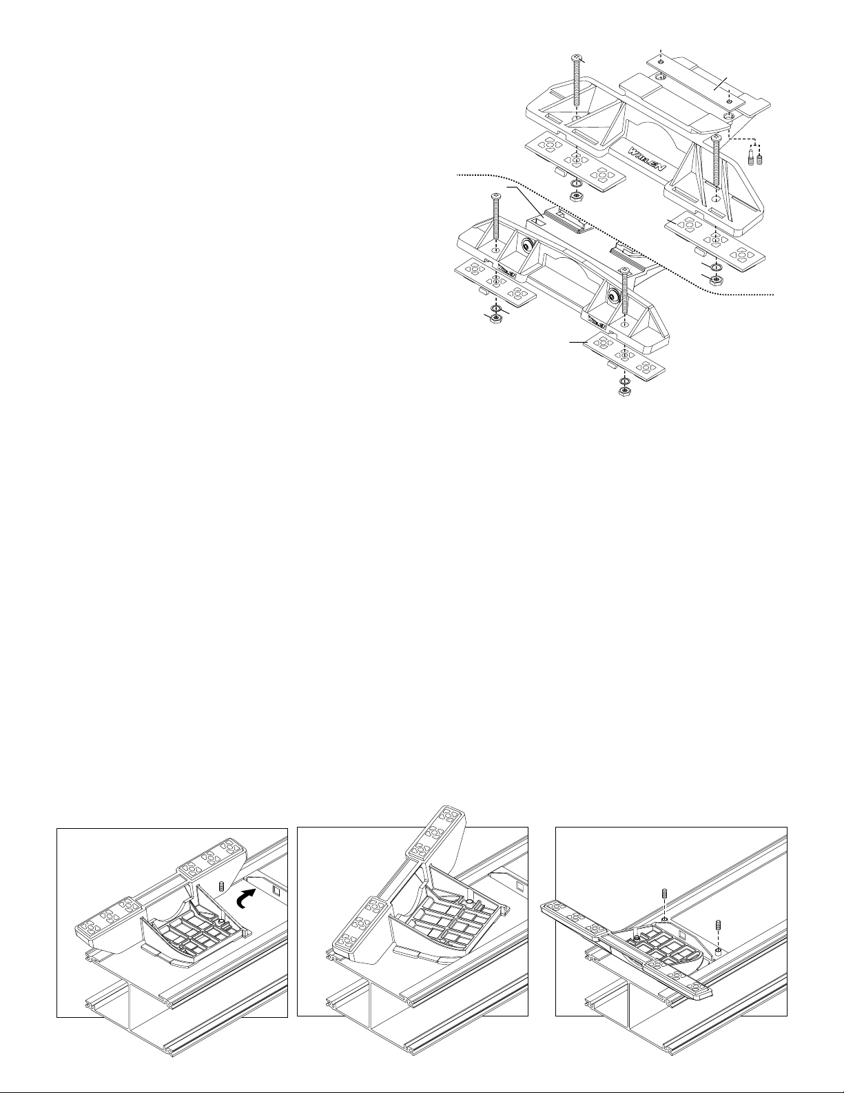
Permanent Mounting:
1. Locate the mounting foot and locking plate included with your
lightbar. If not already present, install the locking plate onto the
mounting foot. When properly positioned, this plate is centered from
side to side on the mounting foot.
2. Flip the lightbar upside-down to expose the bottom of the extrusion
and place the mounting foot onto the extrusion.
3. Rotate the mounting foot 90° in a counter-clockwise direction. Make
sure that the edges of the mounting foot swing into position under the
extrusion mounting lip.
4. Repeat this procedure for the remaining mounting foot and return the
lightbar to its right side-up position.
5. Position the lightbar onto the vehicle roof in the desired mounting
location. One often selected location is directly above the B-pillars.
This area is the strongest part of the roof. Refer to your lightbar
manual for cable exit location, to be sure that the lightbar is facing the
proper direction.
6. Adjust the two mounting feet outwards so that they are as close to
the edge of the roof as possible. Make sure that both mounting feet
are in full contact with the roof. Be sure that there is no less than 1/2”
clearance between the roof and the lightbar at their closest point.
When the mounting feet are in their proper position, lightly tighten the
locking plate allen head set screws.
7. Turn the lightbar upside down and firmly tighten all of the set screws
from step 6 (2 or 4 per side).
8. On the adjustable foot, use the hole in the pad as a guide to drill the
two holes into the mounting foot at the locations shown.
Standard
Mounting
Bolt
Bolt
Locking
Plate
Foot
Mounting
Foot
Base
Nut
Washer
Mounting
Pad
9. Place the lightbar in its final mounting position on the vehicle, mark
the mounting hole locations off onto the mounting surface, remove
the lightbar and drill the mounting holes.
10. Place the lightbar back onto the vehicle lined up with the mounting
holes and secure the mounting feet to the vehicle with the supplied
hardware.
Mounting
Pad
Washer
Nut
Adjustable
Mounting
Foot
Strap Mounting:
1. Locate the mounting foot, anchor plate and locking plate included with
your lightbar. If not already present, install the locking plate onto the
mounting foot. When properly positioned, this plate is centered from sideto-side on the mounting foot.
2. Flip the lightbar upside-down to expose the bottom of the extrusion and
place the mounting foot onto the extrusion.
3. Rotate the mounting foot 90° in a counter-clockwise direction. Make sure
that the edges of the mounting foot swing into position under the extrusion
mounting lip. Install an anchor plate onto the extrusion in the same
manner.
4. Repeat this procedure for the remaining mounting foot and anchor plate
and return the lightbar to its right side-up position.
5. Position the lightbar onto the vehicle roof in the desired mounting location.
One often selected location is directly above the B-pillars. This area is the
strongest part of the roof. Refer to your lightbar manual for cable exit
location, to be sure that the lightbar is facing the proper direction.
6. Adjust the two mounting feet outwards so that they are as close to the
edge of the roof as possible. Both mounting feet must be in full contact
with the roof. Be sure that there is no less than 1/2” clearance between
roof and lightbar at their closest point. When the mounting feet are in their
proper position, lightly tighten the locking plate allen head set screws.
Insert foot into extrusion with locking plate
attached.
ANCHOR
PLATE
Twist mounting foot into
position
7. Return the lightbar to an upside-down position. Slide each anchor plate
outwards until it is fully engaged with its corresponding mounting foot.
With the mounting feet and anchor plates in their proper positions firmly
tighten all of the set screws (2 or 4 per side). Flip the lightbar right side-up
and return it to its mounting position.
8. Open both drivers side doors. In the area directly below the mounting
foot, pull the weatherstrip away from the vehicle so the area where the
mounting strap will be secured is exposed. Repeat for the other side.
9. Insert the mounting strap through the mounting foot. Be sure that the
strap fits flush against the area where it will be secured onto the vehicle.
Insert the tension bolt through the mounting strap and anchor plate, into
the tinnerman nut. Tighten slightly with a long-shafted, Phillips
screwdriver. Repeat procedure for passenger side.
10. If your mounting strap has mounting holes in the end of the strap, use
these holes as a template to drill appropriately sized pilot holes through
the strap and into the vehicle. Repeat for passenger side of the vehicle.
11. Firmly tighten the tension bolts to secure the lightbar to the vehicle.
NOTE: Model MKAJ is an adjustable mounting foot. On this model you
may loosen the screws on the rear of the foot and adjust the angle of the
lightbar. This feature can be used if the angle of the roof is not level with
the road. IMPORTANT: To adjust the leveling screws you must use a
torque wrench set at 35 to 40in./lbs.
Loosely secure foot and locking plate.
Page 2
Page 3

Adjustable Mounting Foot / Model MKAJ
Mounting
Strap
Mounting
Screw
Adjustment
screws
Tension
Bolt
Lock
Washer
Locking
Plate
Tinnerman
Nut
Nut
Mounting
Foot
Mounting
Pad
Anchor
Plate
Model
MKAJ
Tighten
w
ith
set at 35
torque
screw
to
40
Mounting
Screw
s
wrench
in/lbs
Tension
Mounting
Strap
Bolt
Standard Mounting Foot / Model MKEZ
Anchor
Plate
Tinnerman
Mounting
Foot
Locking
Plate
Nut
NUT
FOOT
PLATE
Plate slides into
lightbar extrusion
SET
SCREW
For
with
the Driver-side
of the extrusion
NOTE: Unless otherwise specified, the
lightbar mounting feet must be sitting as
close to the edge of the roof as possible.
Mounting feet must also be in full contact
with the roof and not be hanging off
the edge.
DRILLING THE CABLE ACCESS HOLE
FRONT OF LIGHTBAR
lightbars
cables exiting
For
lightbars
cables exiting
with
the Passenger-side
of the extrusion
5" Mounting Foot
METAL SCREW
BOLT
SHEET
METAL
SCREWS
STRAP
NOTE: The mounting straps are made to fit the contours of individual
NOTE:
vehicles. The strap
for your vehicle
NOTE:
NOTE:
mounting foot, it will assemble differently than the standard
NOTE:
mounting foot. It also uses an extension to compensate for
NOTE:
the extra height. Follow these illustrations for assembly.
NOTE:
Mounting to the lightbar is the same.
shown here is for example only. The strap
may look different. If your lightbar has a 5"
IMPORTANT: For strap mounted bars, be sure you have the right
sized lightbar for your vehicle. The lightbar should be about the
same width as the vehicle roof. If the
lightbar is too large or small it will not
mount properly to the vehicle and
may shift or come loose during driving.
MOUNTING FOOT
EXTENSION
NUT
SPLIT LOCK
WASHER
1/2" Minimum Clearance at Closest Point
TINNERMAN
ANCHOR
VEHICLE ROOF
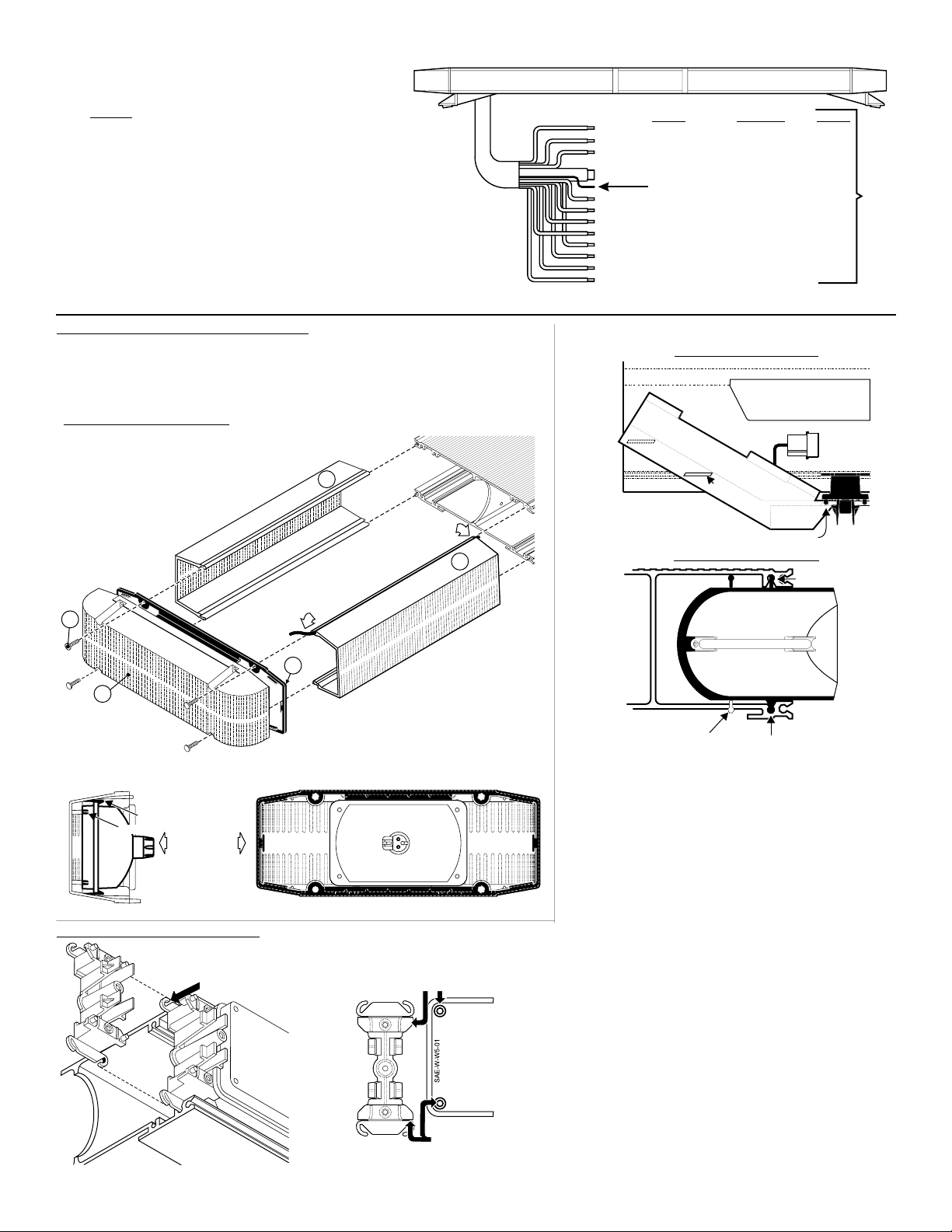
Routing your Edge® Lightbar Cable(s)
1. To protect the headliner from damage caused by drilling the cable access
hole through the vehicle roof, allow a 5” to 7” distance between roof and
headliner by lowering the headliner before drilling.
2. Using a 1” hole saw, drill the cable access hole.
NOTE:There may be a roof support member that spans the distance between
the driver’s and passenger’s side. DO NOT DRILL THROUGH THIS MEMBER!
Adjust the location until the hole can be drilled without contacting this
support member.
Drill cable access hole in appropriate area
for your lightbar (see note)
3. Use a round file to smooth and de-burr the edges of the hole.
4. Insert a 1” grommet (user supplied) into the cable access hole.
5. Insert the cable through the cable access hole into the vehicle. Use RTV silicone to weatherproof the access hole after the cable are pulled
completely into the vehicle.
6. Route the cable to your switch box. It is left to the installation technician’s discretion to select a path for this cable that will both protect the cable from
possible damage and not interfere with the operation of any other vehicle components or equipment. Refer to the instructions included with your
switches for switch wiring information.
Page 3
Page 4
WARNING! All customer supplied wires that connect to
the positive terminal of the battery must be sized to
supply at least 125% of the maximum operating current
and at the battery to carry that load. DO NOT
FUSED
USE CIRCUIT BREAKERS WITH THIS PRODUCT!
WARNING: The strobe light power supply is a high voltage
device. Do not remove the strobe tubes or dismantle the strobe
lightheads while the unit is in operation. Wait 10 minutes after
turning off power before working on the system.
LOW POWER / VIOLET
the Hi/Low feature to function:
Latching Mode:
power supply is “latched” into low power operation. The unit must be turned off and then back
on to restore normal, Hi power operation. (A Momentary Switch is Preferred)
Level Mode -
Applying +12 VDC voltage to the Violet wire for more than 1 second holds the
power supply in low power until voltage is removed. (A Toggle Switch is Preferred)
The type of switch used is dependant on how the operator wishes
By applying +12 VDC voltage to the Violet wire for less than 1 second, the
14 AWG
14 AWG
14 AWG
8AWG
16 AWG
16 AWG
16 AWG
16 AWG
16 AWG
16 AWG
16 AWG
16 AWG
COLOR FUNCTION Fuse @
RED
RED-WHITE
RED-BLACK
BLACK Ground
DRAIN (SHIELD) WIRE
WHITE
YELLOW
VIOLET
WHITE-BLACK
WHITE-BROWN
WHITE-RED
WHITE-BLUE
WHITE-ORANGE
Outer Corner Strobes
Inboard Strobes
N/C
Right Brake Light
Left Brake Light
Low Intensity
Work Lights
Rear Flasher
Front Flasher
Pattern Select
Taillights
15 Amp
15 Amp
-
3 Amp
10 Amp
5 Amp
5 Amp
3 Amp
-
switch box.
Route cable to customer supplied
function.
Apply +12VDC to a control wire to activate its
Endcap, Gasket , Lenses & Spacers Installation
Remove the screws (A) that hold the endcap on and pull the endcap and gasket (C) off.4 (B) Slide
lenses (D) out of the lightbar, to gain access to the extrusion. When reinstalling the lenses and
spacers, install the cord seal (NFPA / See below). When reinstalling the endcap, place the endcap
gasket into it's position on the endcap and line up all the tabs and holes. Spacers (not shown)
mount the same as lenses.
Seal Cord Installation / NFPA Only:
1-
Cut the seal cord approx. 1-1/2" longer than the extrusion on each side.
2-
Rub silicone over the cord seal leaving 3 to 4 inches on one end dry.
3-
Begining with 1 corner lens, start the lens into the bottom
3-
lens track. Place the cord seal onto the groove in the
3-
top of the lens eav 1 to 2 inches
4-
Hold onto the left end of the seal hanging
4-
out and slide the corner lens into
4-
position.
5-
From the opposite end of the
5-
lightbar, pull the seal
5-
cord tight and install
5-
the remaining lenses
5-
and divider.
. L e free.
A
B
BARB
BOSS
Align lighthead
reflector with
4 bosses in
endcap. Press
reflector into place.
D
D
Insert cord seal into track in lens
C
6-
Inspect seal cord for any areas that have wrinkled.
Especially in the areas around the dividers.
6-
Push the lenses together tight and trim excess seal
7-
cord at each end.
7-
snaps into extrusion
NOTE: Lens dividers must
be installed as each lens is
put into position
Halogen Lighthead
Mounting Lightheads to Extrusion
Ears on lighthead bracket
slide inton channels in
extrusion (base).
Lighthead mounting holes
snap into the raised bosses
on the lighthead bracket.
Installing a Corner Strobe
TOP VIEW OF LIGHTBAR BASE
CENTER OF LIGHTBAR
POWER SUPPLY
CORNER STROBE
REAR OF LIGHTBAR
(Drivers Side)
Snap lighthead into mounting bracket
Snap off bottom
bead of reflector
Before working on your strobe lights, disconnect the lightbar
from power and remove the endcap.
light power supply is a high voltage device. Do not
remove the strobe tubes or dismantle the strobe
lightheads in the system while the unit is in operation.
Wait 10 minutes after turning off power before working
on the system.
To remove the lighthead, unsnap it from the
mounting bracket, unplug it, and slide it out of the side of the
lightbar base. If you are replacing the lighthead, snap off the
bottom bead on the new lighthead as shown. Plug the new
lighthead int
the lightbar, slide it into the base and
snap it into the mounting bracket.
TAB
END VIEW OF LIGHTBAR BASE
Lighthead Tabs
slide into base
Slide Spacer in here
WARNING: The strobe
BASE
EXTRUSION
LIG
H
TH
E
A
D
Snap lighthead
into bracket.
Page 4
 Loading...