

Page 1

®
ENGINEERING COMPANY INC.
51 Winthrop Road
Chester, Connecticut 06412-0684
900 Series LED Lighthead
Installation Manual
Phone: (860) 526-9504
Fax: (860) 526-4078
Internet: www.whelen.com
Sales e-mail: autosale@whelen.com
Canadian Sales e-mail: canadiansales@whelen.com
Customer Service e-mail: custserv@whelen.com
Safety First
This document provides all the necessary information to allow your Whelen product to be properly and safely installed.
Before beginning the installation and/or operation of your new product, the installation technician and operator must
read this manual completely. Important information is contained herein that could prevent serious injury or damage.
• Proper installation of this product requires the installer to have a good understanding of automotive electronics,
systems and procedures.
• If mounting this product requires drilling holes, the installer MUST be sure that no vehicle components or other
vital parts could be damaged by the drilling process. Check both sides of the mounting surface before drilling
begins. Also de-burr any holes and remove any metal shards or remnants. Install grommets into all wire
passage holes.
• If this manual states that this product may be mounted with suction cups, magnets, tape or Velcro®, clean the
mounting surface with a 50/50 mix of isopropyl alcohol and water and dry thoroughly.
• Do not install this product or route any wires in the deployment area of your air bag. Equipment mounted or
located in the air bag deployment area will damage or reduce the effectiveness of the air bag, or become a
projectile that could cause serious personal injury or death. Refer to your vehicle owner’s manual for the air bag
deployment area. The User/Installer assumes full responsibility to determine proper mounting location, based
on providing ultimate safety to all passengers inside the vehicle.
• For this product to operate at optimum efficiency, a good electrical connection to chassis ground must be
made. The recommended procedure requires the product ground wire to be connected directly to the NEGATIVE
(-) battery post.
• If this product uses a remote device to activate or control this product, make sure that this control is located in
an area that allows both the vehicle and the control to be operated safely in any driving condition.
• Do not attempt to activate or control this device in a hazardous driving situation.
• This product contains either strobe light(s), halogen light(s), high-intensity LEDs or a combination of these
lights. Do not stare directly into these lights. Momentary blindness and/or eye damage could result.
• Use only soap and water to clean the outer lens. Use of other chemicals could result in premature lens cracking
(crazing) and discoloration. Lenses in this condition have significantly reduced effectiveness and should be
replaced immediately. Inspect and operate this product regularly to confirm its proper operation and mounting
condition. Do not use a pressure washer to clean this product.
• It is recommended that these instructions be stored in a safe place and referred to when performing
maintenance and/or reinstallation of this product.
• FAILURE TO FOLLOW THESE SAFETY PRECAUTIONS AND INSTRUCTIONS COULD RESULT IN DAMAGE TO
THE PRODUCT OR VEHICLE AND/OR SERIOUS INJURY TO YOU AND YOUR PASSENGERS!
Automotive: Lightheads
For warranty information regarding this product, visit www.whelen.com/warranty
©2001 Whelen Engineering Company Inc.
Form No.13629M (120711)
Page 1
Page 2
ARROW / WIDE ANGLE / FLOOD
Colored
This wire color will be whatever the color
of its LED is when light is switched on.
+12 VDC
Black
White/Violet
Ground
Scan-Lock™
Wire Color
Function
BACK-UP
Colored
This wire color will be whatever the color
of its LED is when light is switched on.
+12 VDC
Black
Ground
Wire Color
Function
Yellow
Brown
White
Wht/Vio
Stop Turn/ (+ 12 VDC)
Taillight (+12 VDC)
Ground
Scan-Lock™
Wire Color
Function
BRAKE / TAIL / TURN
Yellow or Red
Black
Yellow or Red
+12 VDC
+12 VDC
, Control Wire 1
, Control Wire 2
Ground
Wire Color
Function
SPLIT / SMT
White
Grey
Black
Positive (+) High Power
Positive (+) Low Power
Ground
Wire Color
Function
COMPARTMENT LIGHT
Wiring:
IMPORTANT NOTICE! This product has been designed for improved
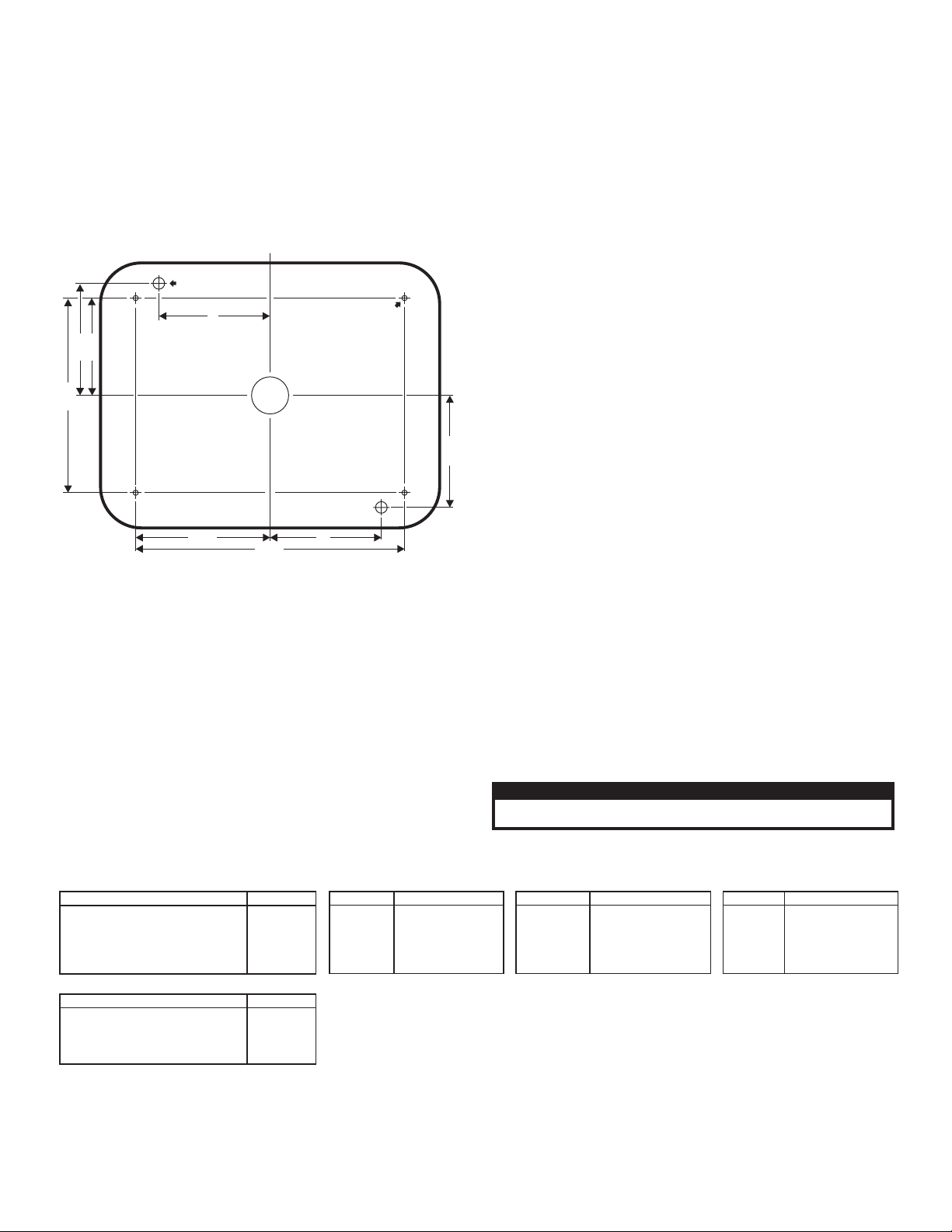
7.250"
3.625"
2.625"
5.250"
3.020"
3.020"
3"
3"
5/16"(.312")Hole
(2 Places)
.250" (1/4")
mounting hole for
grommet (4 places)
1"
WIRE
HOLE
900 Series
Mounting
Dimensions
CAUTION! DO NOT LOOK DIRECTLY AT THESE LED’S WHILE THEY ARE ON.
MOMENTARY BLINDNESS AND/OR EYE DAMAGE COULD RESULT!
IMPORTANT WARNING!
visibility. Prior to installing this product on any vehicle, check your
state motor vehicle codes to confirm that this product complies with
any and all state statutes.
Typical Mounting Style:
1. Using the dimensions from the diagram below, mark off and drill the
two 5/16” diameter vent tube holes and the 1” center wire hole into the
mounting surface. Make sure lighthead will not interfere with existing
equipment and be aware of any items on the opposite side of the
mounting surface.
2. Insert the two vent tubes extending from the rear of the lighthead into
their holes making sure that the lighthead is oriented as shown. Using
a scribe or similar tool, mark off the 4 mounting holes.
3. Using a 1/4” drill bit drill the four mounting holes and install the flange
grommet. Install a rubber grommet (customer supplied) into the 1” wire
hole.
WARNING! All customer supplied wires that connect to the positive
terminal of the battery must be sized to supply at least 125% of the
maximum operating current and FUSED at the battery to carry the
load. DO NOT USE CIRCUIT BREAKERS WITH THIS PRODUCT!
4. Using appropriately sized wires, run the lighthead wires to their
connections (see wiring). Fuse the +12VDC connections at 3 Amps and
test the operation of the lighthead before securing it to the vehicle.
5. Position lighthead components onto mounting surface and secure the
lighthead to the vehicle using four #8 x 1½” sheet metal screws.
This product draws significantly less current than a standard incandescent
automotive bulb. If your flasher does not operate properly, it may be
necessary to replace your existing flasher module with a Whelen 3TERM
flasher module. Contact your sales representative for specific vehicle
application.
Scan-Lock™ (White/Violet)
WARNING: Pattern selection requires the LEDs to be turned on. Do
not look directly at the LEDs while the unit is on.
TO CHANGE PATTERNS: Apply +12 volts to the WHITE/VIOLET wire for
less than 1 second and release to cycle forward to the next available
pattern. Apply +12 volts to the WHITE/VIOLET wire for more than 1
second and release to cycle back to the previous pattern.
TO CHANGE DEFAULT PATTERN: When the desired pattern is
displayed, allow it to run for more than 5 seconds. The lighthead will now
display this pattern when initially activated.
TO RESTORE FACTORY DEFAULT PATTERN: With the power to the
lighthead off, apply +12 volts to the WHITE/VIOLET wire. Now turn power
to the lighthead on. The factory default pattern should now be displayed.
A Normally Open momentary switch can be used to control Scan-Lock™.
Flash Patterns: SignalAlert™ 75 > SignalAlert 150 > SingleFlash 375 >
SingleFlash 150 > SingleFlash 75 > SingleFlash 150 > DoubleFlash 150 >
DoubleFlash 75 > CometFlash® 75 > ActionFlash™ > ModuFlash™ >
ComAlert™ > ActionScan™ > SignalAlert Steady > Steady (Brake) Brake
Patterns: SignalAlert Steady > Steady Brake SYNC Patterns: SignalAlert
75 simultaneous - 75 FPM > SignalAlert 75 alternating - 75 FPM Arrow
Patterns: Sequence to Solid 150 FPM > Sequence to Solid 80 FPM >
Sequence to Solid-Steady On: Fast > Sequence to Solid-Steady On: Slow
> SignalAlert™ To Steady On > Steady On Dual Color Patterns:
SingleFlash 680 alternating > SingleFlash 240 alternating > Singleflash
120 alternating > SingleFlash 150 simultaneous > DoubleFlash 240
alternating > DoubleFlash 120 alternating > DoubleFlash 150
simultaneous > CometFlash 120 alternating
simultaneous > ActionFlash alternating > ActionFlash alternatingsimultaneous > ModuFlash™ alternating > ModuFlash™ simultaneous >
SignalAlert 120 alternating > SignalAlert 100 simultaneous > ActionScan
alternating-simultaneous > Action Single, 4-110 FPM-2-65 FPM > CH1
Steady-CH2 SF120 > CH1 Steady-CH2 Action Single > CH1 Steady-CH2
CometFlash® 120 > Ch1 Steady / CH2 FastAction
IMPORTANT! Before returning this vehicle to active service, visually
confirm the proper operation of this product, as well as all vehicle
components/equipment.
> CometFlash 120
Page 2
Page 3

PART NUMBER KEY:
01-0683738___
TERMINATION
LED/LENS COLOR
STYLE
TERMINATION
0 =
1 =
2 =
3 =
NONE
DEUTSCH
AMP PINS
3 POS. CON.
SHIPPED LOOSE
3 POS. AMP
2 =
2 =
STYLE
2 =
3 =
5 =
6 =
B =
/ MIN
ARROW
WIDE ANGLE
FLOOD
/ MAX
B-T-T
B-T-T
COMPARTMENT LIGHT
B-T-T / CERTIFIED
BTT MAX 24V
BACKUP
9 =
N =
E =
7 =
LED/LENS COLOR
A=
B =
C =
G =
R =
AMBER-AMBER
BLUE-BLUE
WHITE-CLEAR
GREEN-GREEN
RED-RED
1 =
2 =
4 =
5 =
S =
K =
W =
6 =
7 =
8 =
AMBER-CLEAR
BLUE-CLEAR
GREEN-CLEAR
RED-CLEAR
AMB-AMB-AMB
RED-AMB-RED-AMB
RED-RED-RED
AMB-AMB-CLEAR
RED-AMB-CLEAR
RED-RED-CLEAR
OPTIONAL FLANGE KIT / 900 SERIES
PART NUMBER DESCRIPTIONITEMQTY
FLANGE GASKET
38-0481440-00
A1
FLANGE KIT SEALwith
01-0462945-01
*
B1
11-783130-002
FLANGE with SEAL
A
B
234
01-06837382R_
01-06837383A_
01-06837383R_
01-06837385A_
01-06837385B_
01-06837385C_
01-06837385G_
01-06837385R_
01-06837386C_
01-0683738BR_
LIGHTHEAD 900 LED B-T-T (MIN) - RED
LIGHTHEAD 900 LED WIDE ANGLE - AMBER
LIGHTHEAD 900 LED WIDE ANGLE - BLUE
LIGHTHEAD 900 LED WIDE ANGLE - WHITE
LIGHTHEAD 900 LED WIDE ANGLE - GREEN
LIGHTHEAD 900 LED WIDE ANGLE - RED
LIGHTHEAD 900 LED B-T-T (MAX) - RED
LIGHTHEAD 900 LED ARROW - AMBER
LIGHTHEAD 900 LED ARROW - RED
LIGHTHEAD 900 LED FLOOD - WHITE
SCREW, #8 X 1 1/2" PPHSMS
15-081416-240
68-1182268-10
LENS, NON OPTIC - AMBER
68-1182268-30
LENS, NON OPTIC - CLEAR
68-1182268-50
LENS, NON OPTIC - RED
68-1183542-10
LENS, OPTIC - AMBER
68-1183542-20
LENS, OPTIC - BLUE
68-1183542-30
LENS, OPTIC - CLEAR
68-1183542-40
LENS, OPTIC - GREEN
68-1183542-50
LENS, OPTIC - RED
01-0283754-52
01-0283754-13
SUB ASSY. LED ARROW -AMBER
01-0283754-53
SUB ASSY, LED ARROW - RED
01-0283754-15
SUB ASSY, LED WIDE ANGLE -AMBER
01-0283754-25
SUB ASSY, LED WIDE ANGLE - BLUE
01-0283754-35
SUB ASSY, LED WIDE ANGLE - WHITE
01-0283754-45
SUB ASSY, LED WIDE ANGLE - GREEN
01-0283754-55
SUB ASSY, LED WIDE ANGLE - RED
01-0283754-36
SUB ASSY, LED FLOOD - WHITE
01-0283754-5B
10-0522908-**
LABEL, LED LIGHTHEAD
38-0481690-00
GASKET
SUB ASSY, LED B-T-T (MIN) - RED
SUB ASSY, LED BRAKE/TAIL/TURN (MAX) RED
01-06837385S_
LIGHTHEAD 900 LED WIDE ANGLE - AMB/AMB
01-068373857_
LIGHTHEAD 900 LED WIDE ANGLE - RED/AMBER
01-06837385W_
LIGHTHEAD 900 LED WIDE ANGLE - RED/RED
02-0363407-AR
LENS, OPTIC - AMBER/RED
01-0283754-A5
SUB ASSY, LED WIDE ANGLE -AMBER/AMBER
01-0283754-K5
SUB ASSY, LED WIDE ANGLE - RED/AMBER
01-0283754-R5
SUB ASSY, LED WIDE ANGLE - RED/RED
11-786976-000
FLANGE GROMMET, 900 SERIES
SUB ASSY, LED BRAKE/TAIL/TURN (MIN) - RED/DEUTSCH
02-0383754152
02-0383754153
02-0383754113
SUB ASSY, LED ARROW - RED/DEUTSCH
SUB ASSY. LED ARROW -AMBER/DEUTSCH
02-038375415B
02-0383754136
02-0383754155
02-0383754145
02-0383754135
02-0383754125
02-0383754115
SUB ASSY, LED FLOOD - WHITE/DEUTSCH
SUB ASSY, LED WIDE ANGLE - RED/DEUTSCH
SUB ASSY, LED WIDE ANGLE - GREEN/DEUTSCH
SUB ASSY, LED WIDE ANGLE - WHITE/DEUTSCH
SUB ASSY, LED WIDE ANGLE - BLUE/DEUTSCH
SUB ASSY, LED WIDE ANGLE -AMBER/DEUTSCH
SUB ASSY, LED BRAKE/TAIL/TURN (MAX) - RED/DEUTSCH
SUB ASSY, LED WIDE ANGLE -AMB/AMB/DEUTSCH
SUB ASSY, LED WIDE ANGLE - RED/AMB/DEUTSCH
SUB ASSY, LED WIDE ANGLE - RED/RED/DEUTSCH
02-03837541R5
02-03837541K5
02-03837541A5
01-06837389C0
LIGHTHEAD 900 LED COMPARTMENT LIGHT
SUB ASSY, LED COMPARTMENT LIGHT
01-0283754-39
01-0683738NR0
LIGHTHEAD 900 LED B/T/T (CERTIFIED) RED
01-0283754-5N
SUB ASSY, LED B/T/T CERTIFIED - RED
02-0383754252
SUB ASSY, 900 LED BRAKE/TAIL/TURN(MIN)AMP
02-03837542( )3
SUB ASSY, 900 LED ARROW, AMP PINS
02-03837542( )5
SUB ASSY, 900 LED WIDE ANGLE,AMP PINS
02-0383754236
SUB ASSY, 900 LED FLOOD, AMP PINS
02-0383754258
SUB ASSY, 900 LED BRAKE/TAIL/TURN (MAX)AMP
LIGHTHEAD 900 LED B-T-T (MIN) - AMP
LIGHTHEAD 900 LED ARROW - AMP
LIGHTHEAD 900 LED WIDE ANGLE - AMP
LIGHTHEAD 900 LED FLOOD -WHITE, AMP
LIGHTHEAD 900 LED B-T-T (MAX) - AMP
39-0403013-04
HOUSING, 3 POS PIN AMP
01-0683738BR2
01-06837386C2
01-06837385( )2
01-06837383( )2
01-06837382R2
01-0683738ER0
LIGHTHEAD 900 LED B-T-T (MAX) 24V - RED
SUB ASSY, 900 LED BRAKE/TAIL/TURN (MAX) 24V
01-0283754-5E
LENS, OPTIC SCENE - CLEAR
68-1983892-30
01-06837387C0
LIGHTHEAD 900 LED BACK-UP - WHITE
02-038375435B
SUB ASSY, LED BRAKE/TAIL/TURN (MAX) - RED/3PAMP
4
1
1
1
1
1
4
1
1
1
1
1
4
1
1
1
1
1
4
1
1
1
A/R
1
1
4
1
1
1
A/R
1
1
4
1
1
1
A/R
A/R
A/R
A/R
A/R
A/R
1
4
1
1
1
A/R
A/R
A/R
A/R
A/R
A/R
1
-
4
1
1
1
A/R
1
1
4
1
1
1
1
1
4
1
1
1
A/R
1
A/R
4
1
1
1
A/R
A/R
1
A/R
4
1
1
1
A/R
1
A/R
4
1
A/R
1
1
1
A/R
A/R
4
1
A/R
1
1
1
A/R
4
1
A/R
1
1
1
A/R
4
1
A/R
1
1
1
A/R
4
1
A/R
1
1
1
A/R
4
1
A/R
1
1
1
A/R
4
1
A/R
1
1
1
A/R
4
1
A/R
1
1
1
A/R
4
1
A/R
1
1
1
A/R
A/R
SUB ASSY. LED ARROW -AMBER/3P AMP
02-0383754313
4
1
A/R
1
1
1
A/R
2
3
11
12
13
14
15
16
17
18
19
20
4
5
6
7
8
9
10
1
21
22
30
31
32
33
34
35
36
37
38
39
23
24
25
26
27
28
29
40
41
49
50
51
42
43
44
45
46
47
48
ITEM
PART NUMBER
DESCRIPTION
QTY QTY QTY QTYQTYQTYQTYQTYQTYQTYQTYQTYQTYQTYQTYQTYQTYQTYQTY QTY QTY QTY
48
4645
4241
40
50
3635
27
1918
10
47
21
1
22
13
30
16
33
14
31
17
34
15
32
586972349
38 39
44
24 25
26
37
5143
2928
1211
Page 3
 Loading...