

Page 1

®
ENGINEERING COMPANY INC.
51 Winthrop Road
Chester, Connecticut 06412-0684
Phone: (860) 526-9504
Fax: (860) 526-4078
Internet: www.whelen.com
Sales e-mail: autosale@whelen.com
Canadian Sales e-mail: canadiansales@whelen.com
Customer Service e-mail: custserv@whelen.com
Installation Guide:
800D Series Strobe Beacon
Whelen’s emergency vehicle warning devices must be properly mounted and wired in order to be effective and safe. Read and follow all of Whelen’s
written instructions when installing or using this device. Emergency vehicles are often operated under high speed stressful conditions which must be
accounted for when installing all emergency warning devices. Controls should be placed within convenient reach of the operator so that he can operate
the system without taking his eyes off the roadway. Emergency warning devices can require high electrical voltages and/or currents. Properly protect and
use caution around live electrical connections.Grounding or shorting of electrical connections can cause high current arcing, which can cause personal
injury and/or vehicle damage, including fire. Many electronic devices used in emergency vehicles can create or be affected by electromagnetic
interference. Therefore, after installation of any electronic device it is necessary to test all electronic equipment simultaneously to insure that they operate
free of interference from other components within the vehicle. Never power emergency warning equipment from the same circuit or share the same
grounding circuit with radio communication equipment. All devices should be mounted in accordance with the manufacturer’s instructions and securely
fastened to vehicle elements of sufficient strength to withstand the forces applied to the device. Driver and/or passenger air bags (SRS) will affect the way
equipment should be mounted. This device should be mounted by permanent installation and within the zones specified by the vehicle manufacturer, if
any. Any device mounted in the deployment area of an air bag will damage or reduce the effectiveness of the air bag and may damage or dislodge the
device. Installer must be sure that this device, its mounting hardware and electrical supply wiring does not interfere with the air bag or the SRS wiring or
sensors. Mounting the unit inside the vehicle by a method other than permanent installation is not recommended as unit may become dislodged during
swerving; sudden braking or collision. Failure to follow instructions can result in personal injury. Whelen assumes no liability for any loss resulting from the
use of this warning device. PROPER INSTALLATION COMBINED WITH OPERATOR TRAINING IN THE PROPER USE OF EMERGENCY WARNING
DEVICES IS ESSENTIAL TO INSURE THE SAFETY OF EMERGENCY PERSONNEL AND THE PUBLIC.
Warnings to Users
Warnings to Installers
Whelen’s emergency vehicle warning devices are intended to alert other operators and pedestrians to the presence and operation of emergency vehicles
and personnel. However, the use of this or any other Whelen emergency warning device does not guarantee that you will have the right-of-way or that
other drivers and pedestrians will properly heed an emergency warning signal. Never assume you have the right-of-way. It is your responsibility to proceed
safely before entering an intersection, driving against traffic, responding at a high rate of speed, or walking on or around traffic lanes. Emergency vehicle
warning devices should be tested on a daily basis to ensure that they operate properly. When in actual use, the operator must ensure that both visual and
audible warnings are not blocked by vehicle components (i.e.: open trunks or compartment doors), people, vehicles, or other obstructions. It is the user’s
responsibility to understand and obey all laws regarding emergency warning devices. The user should be familiar with all applicable laws and regulations
prior to the use of any emergency vehicle warning device. Whelen’s audible warning devices are designed to project sound in a forward direction away
from the vehicle occupants. However, because sustained periodic exposure to loud sounds can cause hearing loss, all audible warning devices should be
installed and operated in accordance with the standards established by the National Fire Protection Association.
Safety First
This document provides all the necessary information to allow your Whelen product to be properly and safely installed. Before beginning the installation
and/or operation of your new product, the installation technician and operator must read this manual completely. Important information is contained herein
that could prevent serious injury or damage.
• Proper installation of this product requires the installer to have a good understanding of automotive electronics, systems and procedures.
• Whelen Engineering requires the use of waterproof butt splices and/or connectors if that connector could be exposed to moisture.
• Failure to use specified installation parts and/or hardware will void the product warranty.
• If mounting this product requires drilling holes, the installer MUST be sure that no vehicle components or other vital parts could be damaged
by the drilling process. Check both sides of the mounting surface before drilling begins. Also de-burr the holes and remove any metal shards
or remnants. Install grommets into all wire passage holes.
• If this manual states that this product may be mounted with suction cups, magnets, tape or Velcro®, clean the mounting surface with a 50/50
mix of isopropyl alcohol and water and dry thoroughly.
• Do not install this product or route any wires in the deployment area of your air bag. Equipment mounted or located in the air bag deployment
area will damage or reduce the effectiveness of the air bag, or become a projectile that could cause serious personal injury or death. Refer to
your vehicle owner’s manual for the air bag deployment area. The User/Installer assumes full responsibility to determine proper mounting
location, based on providing ultimate safety to all passengers inside the vehicle.
• For this product to operate at optimum efficiency, a good electrical connection to chassis ground must be made. The recommended
procedure requires the product ground wire to be connected directly to the NEGATIVE (-) battery post (this does not include products that use
cigar power cords).
• If this product uses a remote device for activation or control, make sure that this device is located in an area that allows both the vehicle and
the device to be operated safely in any driving condition.
• Do not attempt to activate or control this device in a hazardous driving situation.
• This product contains either strobe light(s), halogen light(s), high-intensity LEDs or a combination of these lights. Do not stare directly into
these lights. Momentary blindness and/or eye damage could result.
• Use only soap and water to clean the outer lens. Use of other chemicals could result in premature lens cracking (crazing) and discoloration.
Lenses in this condition have significantly reduced effectiveness and should be replaced immediately. Inspect and operate this product
regularly to confirm its proper operation and mounting condition. Do not use a pressure washer to clean this product.
• It is recommended that these instructions be stored in a safe place and referred to when performing maintenance and/or reinstallation of this
product.
• FAILURE TO FOLLOW THESE SAFETY PRECAUTIONS AND INSTRUCTIONS COULD RESULT IN DAMAGE TO THE PRODUCT OR VEHICLE
Automotive: Beacons
AND/OR SERIOUS INJURY TO YOU AND YOUR PASSENGERS!
©1997 Whelen Engineering Company Inc.
Form No.13207G (061614)
For warranty information regarding this product, visit www.whelen.com/warranty
Page 1
Page 2
The 800D Series Strobe Beacon features a combination base which may
PERMANENT
MOUNT
Dimples
Dimples
Drill wire access
hole here
1/2" Diameter
6.81"
Diameter
Base
5.937 B.C.
Three .218
Diameter Holes
Equally spaced
#10 Clearance
FLANGE
MOUNT
be used for either Flange Mount, 1” (NPT) Pipe Mount, Permanent Mount,
Magnetic or Magnetic-Suction mount. The threading for a 1 inch (NPT)
pipe mounting is precast in the die-cast base.
WARNING! The strobe light power supply is a high voltage device.
Do not remove strobe tubes or dismantle strobe light head
assemblies in the system while it is in operation. Wait 10 minutes
after turning off power before starting work or any trouble shooting.
• Input Voltage: 12VDC and 24VDC
• Input Current: 2.5A @12.8V and 1.5A @ 25.6V
•Output Power: 25 Watts
• 4 Selectable Flash Patterns.
• Selectable Manual Hi/Low Intensity Mode.
• Automatic Photocell Hi/Low Intensity Mode (Optional).
• Flange / Pipe / Permanent / Magnetic-Suction Mounting.
• Hi/Off/Low Intensity Switch. (Optional)
• 4 Pattern Beacon Controller with Diagnostic & Manual Hi/
Low Intensity Control. (Optional)
• Factory Installed Cruise Light. (Optional)
Installation: FLANGE MOUNT
1. Using the base gasket as a template, mark the three mounting holes
and the center wire access hole onto the mounting surface.
2. Drill holes for the three 10 X 5/8” pan head sheet metal mounting
screws. (supplied)
3. Drill the wire access
hole using a 1/2” drill.
Install a rubber
grommet in the wire
access hole to
protect the wires.
4. Place base gasket on
mounting surface
aligned with the holes
in the mounting
surface. After
connecting the strobe
beacon to the power
cable, feed the wires
through the wire
access hole. Place strobe beacon into proper position and slip
mounting collar over the strobe beacon to fit around base of the unit.
Align the three holes in the mounting collar with the three mounting
holes in the base gasket and mounting surface. Use the three
enclosed mounting screws to attach the strobe beacon to the
mounting surface.
Installation: PIPE MOUNT
1. Feed power cable through the 1 inch pipe and connect the cable to
the wires of the 800D Series strobe beacon.
2. Screw the beacon to the threads on the 1 inch pipe, taking precaution
not to damage the connected power wires.
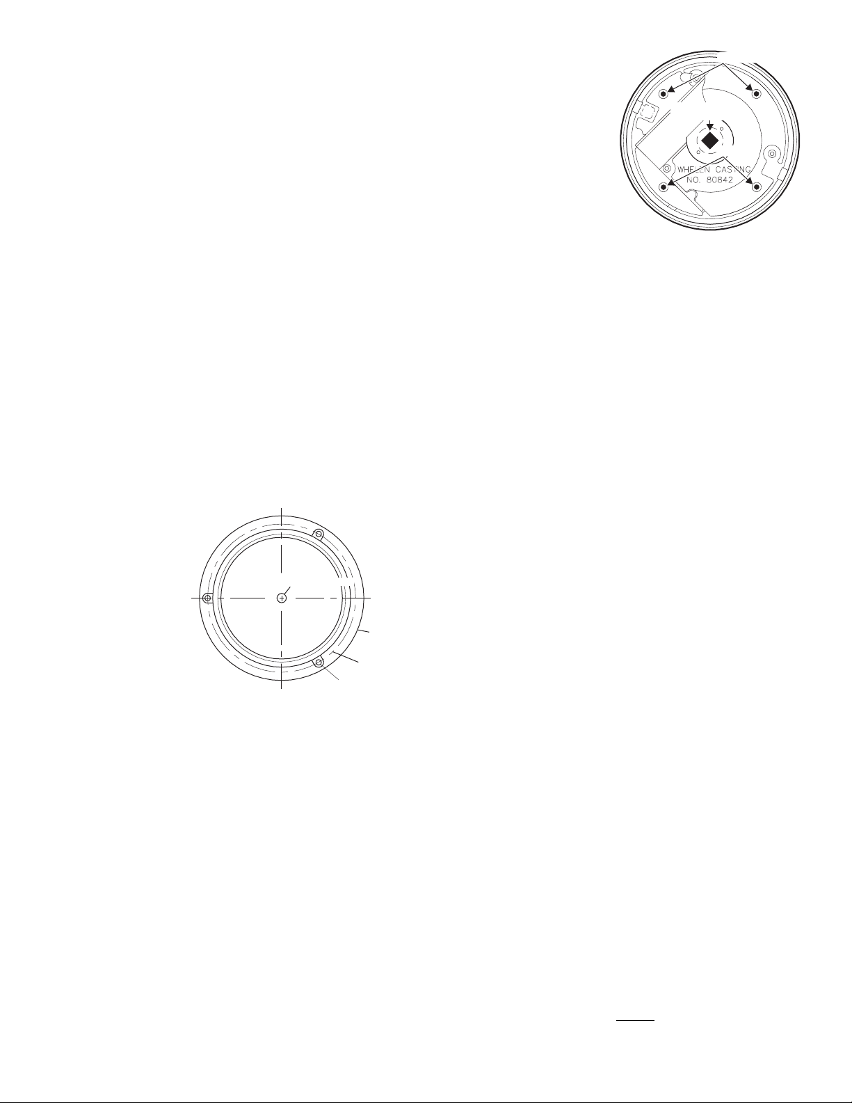
2. Locate the four dimples
equally spaced within the
perimeter of the die-cast base
of the power supply
assembly. Punch these
dimples out to create a hole
for the mounting screws.
3. Using the base of the power
supply assembly as a
template mark the four
mounting holes on the
mounting surface. Mark in the
center between the four
mounting holes the location of
the wire access hole.
4. Drill mounting holes in the mounting surface to fit customer supplied
mounting hardware. Also drill a wire access hole using a 1/2 inch
drill. Install a rubber grommet in the wire access hole to protect the
wires.
5. Base gasket will be used between the strobe beacon base and the
mounting surface. Cut the gasket along perforation to fit the diameter
of the base.
6. After connecting the strobe light beacon to the power cable, feed the
wires through the cable access hole and place the base with the
gasket on the mounting surface, lining up the mounting holes in the
base with the ones in the mounting surface. Secure the strobe light
beacon base firmly to the mounting surface with customer supplied
hardware.
7. Reassemble the strobe light beacon.
Temporary Mounting (Magnetic, Suction Cup, etc.)
With the magnetic or magnetic/suction cup mounting options you will be
able to mount your strobe so that you can remove it if necessary and
avoid drilling.
Installation: Magnetic/suction
Thoroughly clean the proposed mounting surface prior to mounting. For
suction cup mounting, wipe the suction cup clean, place the beacon onto
its mounting surface and apply gentle pressure to ensure a good seal has
been achieved. The Magnetic/Suction Cups mount the same way as
standard suction cups but are best suited to a flat, steel surface.
Installation: Magnetic
Place beacon onto mounting surface and plug into vehicle cigar lighter.
Removing Dome & Strobe Power Supply Assembly:
1. Remove the polycarbonate optic dome from the base by removing
the two base screws (Fig. 11).
2. Remove the 3 screws that hold down the strobe power supply
assembly and separate it from the base.
3. Remove the spring clip and insulator.
See important information about removing spring clip on next page)
IMPORTANT: Be sure to tape or remove any unused wires.
WARNING! The use of any magnetically mounted warning beacon on
the outside of a vehicle while in motion is not recommended and is
at the sole discretion and risk of the use
Installation: PERMANENT MOUNT
This mounting of the 800D Series strobe beacon is a tamper proof way to
secure the unit to the mounting surface. The mounting screws are hidden
inside the base, and are not accessible unless the strobe beacon is
disassembled.
1. Remove the polycarbonate optic dome from the base (see
“Removing Dome & Strobe Power Supply Assembly”).
WARNING! Beacons equipped with cigar cords are intended for
short duration, intermittent operation only! Prolonged operation
requires the beacon to be wired to the vehicle.
WARNING! All customer supplied wires that connect to the positive
terminal of the battery must be sized to supply at least 125% of the
maximum operating current and FUSED
load. DO NOT USE CIRCUIT BREAKERS WITH THIS PRODUCT!
at the battery to carry that
Page 2
Page 3

Assembly of strobe power supply assembly to die cast base, to
Strobe
Power
Supply
Assembly
Input
Control
Pigtail
Assembly
Tape
Green
Wire
Optic
Dome
- Tall
(if present)
Optic
Dome
(if present)
Base
Screws
Base
Screws
Spring
Clip
Xistor Mt.
Die Cast
Base
1" NPT
Pipe
Mounting
Screws
1234
4321
BROWN
WHITE
BLACK
RED
123
123
ensure prevention of an electrical short circuit between parts:
IMPORTANT: Read all warnings on first page before attempting disassembly
of the strobe light power supply and base.
This page describes the assembly procedure
of the strobe light power supply to the die-cast
base. It is extremely important that the assembly steps, as described below, are precisely
followed to insure the proper insulation of
the strobe light power supply from the die cast
aluminum base.
FIGURE 1. Lower the power supply assembly
onto the die-cast base, with the 3 mounting
holes lined up with the holes located on the
three mounting studs of the cast aluminum
base. During this assembly operation, the
transistor on the power supply assembly has
to be positioned on the outside of the
transistor mounting boss. Secure the strobe
light power supply assembly to the mounting
studs with enclosed self- tapping screws.
FIGURE 2. Slightly bend the transistor on the
power supply away from the transistor mounting boss. Slip the Cho-Therm insulator behind
the transistor with the hole directed towards
the top (See figure 4”A”).
Position the top of the Cho-Therm insulator
against the circuit board of the power supply
assembly, making sure that some of it shows
below the transistor (See figure 4”B”). It is
important that the transistor on the power supply assembly does not contact the transistor
mounting boss at any place, to prevent a damaging electrical short circuit between the
strobe power supply and the die-cast base.
FIGURE 3. Use the transistor
spring clip to secure firmly the
Cho-Therm insulator and the
power supply transistor to the
mounting boss of the die-cast
base. Wrap one end of the clip
around one side of the mounting
boss, then press the other end in
position using needle nose pliers.
TOP VIEW OF TRANSISTOR
MOUNTING BOSS
FIGURE 5
WRAP ONE END OF TRANSISTOR
SPRING CLIP AROUND ONE END
OF TRANSISTOR MOUNTING BOSS
CHO-THERM INSULATOR AND TRANSISTOR TO
BE SECURED BETWEEN TRANSISTOR SPRING
CLIP AND TRANSISTOR MOUNTING BOSS.
PUSH OTHER END OF TRANSISTOR SPRING
CLIP AROUND OTHER END OF TRANSISTOR
MOUNTING BOSS
Page 3
Page 4

BROWN
WHITE
BROWN
WHITE
BROWN
WHITE
BROWN
WHITE
CometFlash®
SingleFlash
DoubleFlash
ActionFlash™
BATTERY
MODEL 800D STANDARD. HIGH-OFF-LOW SWITCHING.
NOTE: Cut VIOLET
(looped) wire, run it out of
unitwithBLK&REDwires.
When VIO wire is grounded,
you are in high mode When
VIOwireisfloatingyouare
in low mode.
Switches & fuses are customer supplied. 5 AMP fuse: 3 AMP fuse: .12 VDC 24 VDC
Switch control wiring schematics / 800D Strobe Light Series
TO STROBE
LIGHT HEAD
DOUBLE POLE, DOUBLE THROW
CENTER OFF SWITCH (REAR VIEW)
TO STROBE
LIGHT HEAD
MODEL 800D STANDARD. ON/OFF SWITCHING / HIGH POWER ONLY.
BLK / NEG. (-)
RED POS (+)/.
ON/OFF
SWITCH
BLK NEG (-)/.
RED POS (+)/.
RED POS (+)/.
BLK NEG (-)/.
VIO NEG (-) HI/LOW/.
DOUBLE POLE, DOUBLE THROW
CTR. OFF SWITCH (REAR VIEW)
TO STROBE
LIGHT HEAD
MODEL 800D with CRUISE LIGHT OPTION.
NOTE: Cruise lt.
is 12 VDC or 24
VDC bulb.
NOTE: Strobe light is
controlled by DPDT
CENTER OFF switch
control, & cruise light is
controlled by ON/OFF
switch control.
BLK / NEG. (-)
RED POS. (+)/
RED POS (+)/.
BLK NEG (-)/.
VIO NEG (-) HI/LOW/.
GRY POS (+) CRUISE LT, 12 OR 24 VDC/.
DOUBLE POLE, DOUBLE THROW
CENTER OFF SWITCH (REAR VIEW)
TO STROBE
LIGHT HEAD
NOTE: Cruise
Lt.is12VDCor
24 VDC bulb.
MODEL 800D WITH CRUISE LIGHT OPTION.
NOTE: Strobe
& cruise lights
are connected
to same DPDT
CENTER OFF
switch control.
BLK NEG (-)/.
RED POS (+)/.
RED POS (+)/.
BLK NEG (-)/.
VIO NEG (-) HI/LOW/.
GRAY POS (+) CRUISE L
12 OR 24 VDC
/. T.
FUSE
FUSE
FUSE
FUSE
1AMP
FUSE
BATTERY
BATTERY
BATTERY
BATTERY
CUSTOMER OPTIONS
123
Cut VIOLET wire here
1234
4321
123
Extend through base here
Fig. 12
®
Fuse:
12VDC - 5 AMP
24VDC - 3 AMP
(Customer Supplied)
GRY
CRUISE
WIRING DIAGRAM
ON/OFF
RED
BLK(GND)
HI/LOW CTRL
PATTERN 1
PATTERN 2
VIO
BRN
WHT
GRN
LED DIAG.
(+)
Battery
(-)
Hi/Low Intensity Option:
1. Take dome and strobe power supply assembly apart. (see
“Removing Dome and Strobe Power Supply Assembly”)
2. Locate the VIOLET (looped) wire, cut it at pin 2, and run it out of the
bottom of the unit with
the BLACK and RED
wires.
3. Reassemble the unit.
4. Now, if you ground
the VIOLET wire, your
light will run at high
intensity, and if you
tape off the VIOLET
wire, your light will run
at low intensity. You
may want to install a
two position switch so
that you can alternate between the two
functions.
Jumper Options:
There are several options you can utilize by cutting one, both or neither of
the jumpers located inside the unit (the jumpers are labeled JU1 and
JU2.).
A. You may operate your strobe at either high or low intensity (default
setting). Leave both jumpers intact and follow the instructions under
“Hi/Low Intensity Option”.
B. Your strobe may also be
equipped with the
optional “Photocell
function”. This will automatically adjust the
intensity of the strobe
light according to the
ambient light (darkness
switches the beacon to
low power, while daylight switches the beacon to high power). To
engage this function
you must cut the JU2
jumper and leave the
JU1 jumper intact. Then
clip the VIOLET wire
and tape it off (see “Hi/Low Intensity Option”). Now the photocell
option is always engaged. If you want to be able to turn this function
on or off manually, you must also attach the VIOLET wire to a switch
that will ground or disconnect it. When you switch to “ground” the light
will always be at high intensity. When you switch to “disconnect” the
light will return to the photocell function.
C. If you want your strobe to turn on automatically during the day and off
at night, cut the JU1 jumper and leave JU2 jumper intact.
D. If you want your strobe to turn off automatically during the day and on
at night, cut both the JU1 and JU2 jumpers.
IMPORTANT NOTE: Both “C” and “D” are usually used for remote
applications. Once you convert to either of these functions you will not be
able use the light any other way.
Flash Pattern Options:
The default flash pattern for the 800D is CometFlash®. You may choose
from several other patterns by making a few simple changes.
1. Disassemble the unit as described under “Removing the Dome and
Strobe Power Supply
Assembly”.
2. Locate the input control
pigtail assembly and
plug it in to the extra
connector coming out of
the Power Supply.
3. Run the BROWN &
WHITE wires out
through the center of
the base as shown.
Tape off the unused
GREEN wire.
4. Reassemble the unit and
you are ready to choose
your options.
To Select SingleFlash: Ground
the WHITE wire and tape off the
BROWN wire.
To Select DoubleFlash: Ground
the BROWN wire and tape off
the WHITE wire.
To Select ActionFlash™:
Ground both the WHITE and
BROWN wires.
IMPORTANT! Before returning
the vehicle to active service,
visually confirm the proper
operation of this product, as
well as all vehicle
components/equipment.
Page 4
 Loading...