

Page 1
®
ENGINEERING COMPANY INC.
Route 145, Winthrop Road,
Chester, Connecticut 06412
Phone: (860) 526-9504
Fax: (860) 526-2009
Internet: www.whelen.com
Sales/Service e-mail: aviation@whelen.com
Installation Guide: 71110( )-series
Models 7111007, 7111008
P/N: 01-0771110-07, 01-0771110-08
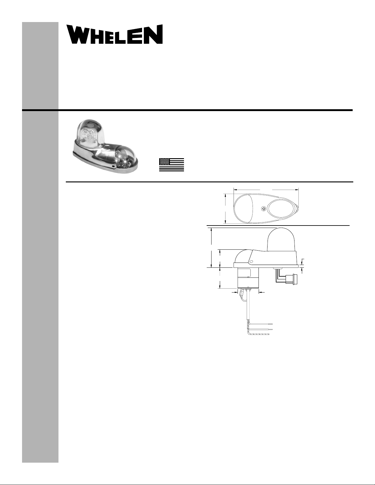
LED Forward Position Light/
Strobe Assembly
POSITION LIGHT:
Operational Voltage: . . . . . . . . . . . 28 VDC (nominal)
Input Current: . . . . . . . . . . . . . . . . 0.25 Amps
EQUIPMENT LIMITATIONS: An approved lighting system
consists of two lights, one located on each wingtip. The
baseplate must be mounted parallel to the vertical and
horizontal centerlines of the aircraft to project the patterns
properly. The strobe tube assembly must be connected to a
strobe power supply, such as Whelen model 70888, 70879
or other approved models.
Certain types of installations may require additional testing.
CONTINUED AIRWORTHINESS: The 71110( ) series LED
wingtip position light assembly is designed with 3 LED’s.
Should any one LED fails, the unit must be repaired or
replaced.
NOTE:
To reduce eye strain, use an optical filter (such as dark
glasses or a blue covering dome) during LED inspection.
Inspect the lens. Replace if there is excessive scratching,
discoloration, pitting or cracking.
INSTALLATION PROCEDURES: The following information
is to assist in the installation of a Whelen 71110( ) LED
Forward Position Light/Strobe System. The installation
procedure described in the following text will be confined to a
single light installation, but is identical for multiple light
installations.
1. Choose the appropriate 71110( ) light assembly.
2. Using the mounting detail information provided,
prepare the aircraft for means to secure the light
assembly.
3. Connect the position light inputs according to the chart
shown. Connect the power lead to an appropriate sized
breaker. Connections to be in accordance with FAA
approved methods. Connect the strobe, J1 to the
strobe power supply as shown.
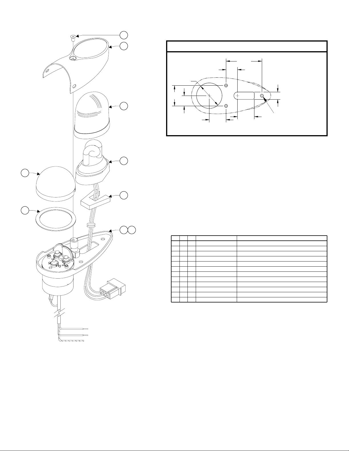
4. Carefully remove the shroud from the light assembly.
CAUTION! Do not touch the LED lens surface with
either fingers or sharp objects. This could soil and/or
Aviation
damage the lens and effect the optical performance of
the LEDs.
TSO-C30c
TYPES I, II
APPROVED
TSO-C96a
CLASS II
APPROVED
MADE IN THE U.S.A.
The conditions and tests required for TSO approval of this
article are minimum performance standards. It is the
responsibility of those installing this article either on or
within a specific type or class of aircraft to determine that
the aircraft installation conditions are within the TSO
standards. TSO articles must have separate approval for
installation in aircraft. The article may be installed only if
performed under 14 CFR part 43 or the applicable
airworthiness requirements.
3.88
7111007
7111008
1.78
(28V)
7111007
7111008
2.35
1.08
J1
1.15
Ø1.25
2/C 20 AWG
ETFE CABLE
LEAD LENGTH
12" ±1
WHITE (+28VDC)
BLACK (-) GROUND
SHIELD
5. Using the appropriate hardware, install light assembly and insure
that all leads are clear of any obstructions and secured as
required. Secure light assembly using vibration resistant threaded
fasteners.
6. Reinstall the lens so that the two notches are positioned under the
shroud, with each notch equadistant to the centerline. Confirm
proper gasket fit.
7. Install lens retainer. Reinsert #6 flat head screw and tighten firmly.
8. When necessary, waterproof the light base to aircraft. Apply single
part silicone (RTV) or equivalent around any open area where
water could get in.
9. Check all avionics systems for interference from the installation.
10. A flight check should be performed by a properly certified pilot.
11. Update aircraft records, complete Form 337 and obtain FAA field
approval for installation, as necessary.
POS 3 - WHITE (TRIGGER)
POS 2 - BLACK (CATHODE)
POS 1 - RED (ANODE)
(28V)
.17
©2011 Whelen Engineering Company Inc.
Form No.14488 (050511)
Page 1
Page 2
9
8
MOUNTING DIMENSIONS
1.75
.56
1.31 DIA.
1.00
.36
.50
7
.820
.82
3 x 0.140 DIA
MOUNTING HOLE
FOR #6-32 SCREWS
6
4
5
3
12
QTY. QTY.
*
-
1
1
1
1
1
11
1
1
ITEM
PART NUMBER
*
1
-
1
1
1
1
1
1
01-0771110-07
01-0771110-08
1
01-0271179-07
2
01-0271179-08
3
38-0230021-00
4
68-3950902A30
5
38-0130107-00
6
36-0050626-01
7
68-2290005-34
8
19-171122-100
14-0050508-27
9
7111007 POS/STROBE LIGHT, 28V (GRN)
7111008 POS/STROBE LIGHT, 28V (RED)
71110 ASS'Y, POSITION/STROBE LIGHT 28V (GRN)
71110 ASS'Y, POSITION/STROBE LIGHT 28V (RED)
GASKET, W-1283/W-1285/A650
LENS, CLEAR FWD POSITION LIGHT HARDCOAT
GASKET, A427-4 1/4" THICK
ASS'Y, FLASHTUBE 6.00" LEADS W/GROMMET
LENS, CLEAR/COATED A612
RETAINER, LENS MODEL 71110 IRIDITE/COMPLETE
SCREW, 6-32 5/16 PFHMS CSINK MS51959-27
DESCRIPTION
Page 2
 Loading...