

Page 1

®
ENGINEERING COMPANY INC.
51 Winthrop Road
Chester, Connecticut 06412-0684
700 Series Halogen Lighthead
Installation Guide:
Phone: (860) 526-9504
Fax: (860) 526-4078
Internet: www.whelen.com
Sales e-mail: autosale@whelen.com
Canadian Sales e-mail: canadiansales@whelen.com
Customer Service e-mail: custserv@whelen.com
Safety First
This document provides all the necessary information to allow your Whelen product to be properly and safely installed.
Before beginning the installation and/or operation of your new product, the installation technician and operator must
read this manual completely. Important information is contained herein that could prevent serious injury or damage.
• Proper installation of this product requires the installer to have a good understanding of automotive electronics,
systems and procedures.
• Failure to use specified installation parts and/or hardware will void the product warranty!
• If mounting this product requires drilling holes, the installer MUST be sure that no vehicle components or other
vital parts could be damaged by the drilling process. Check both sides of the mounting surface before drilling
begins. Also de-burr any holes and remove any metal shards or remnants. Install grommets into all wire
passage holes.
• If this manual states that this product may be mounted with suction cups, magnets, tape or Velcro®, clean the
mounting surface with a 50/50 mix of isopropyl alcohol and water and dry thoroughly.
• Do not install this product or route any wires in the deployment area of your air bag. Equipment mounted or
located in the air bag deployment area will damage or reduce the effectiveness of the air bag, or become a
projectile that could cause serious personal injury or death. Refer to your vehicle owner’s manual for the air bag
deployment area. The User/Installer assumes full responsibility to determine proper mounting location, based
on providing ultimate safety to all passengers inside the vehicle.
• For this product to operate at optimum efficiency, a good electrical connection to chassis ground must be
made. The recommended procedure requires the product ground wire to be connected directly to the NEGATIVE
(-) battery post.
• If this product uses a remote device to activate or control this product, make sure that this control is located in
an area that allows both the vehicle and the control to be operated safely in any driving condition.
• Do not attempt to activate or control this device in a hazardous driving situation.
• This product contains either strobe light(s), halogen light(s), high-intensity LEDs or a combination of these
lights. Do not stare directly into these lights. Momentary blindness and/or eye damage could result.
• Use only soap and water to clean the outer lens. Use of other chemicals could result in premature lens cracking
(crazing) and discoloration. Lenses in this condition have significantly reduced effectiveness and should be
replaced immediately. Inspect and operate this product regularly to confirm its proper operation and mounting
condition. Do not use a pressure washer to clean this product.
• It is recommended that these instructions be stored in a safe place and referred to when performing
maintenance and/or reinstallation of this product.
• FAILURE TO FOLLOW THESE SAFETY PRECAUTIONS AND INSTRUCTIONS COULD RESULT IN DAMAGE TO
THE PRODUCT OR VEHICLE AND/OR SERIOUS INJURY TO YOU AND YOUR PASSENGERS!
Automotive: Lightheads
For warranty information regarding this product, visit www.whelen.com/warranty
©2001 Whelen Engineering Company Inc.
Form No.13626H (120811)
Page 1
Page 2
Available Mounting Options
Housing (w/studs):
Housing:
Mounting Hardware & Gasket:
11-483530-011
11-483530-111
01-0483596-00
Housing:
Housing w/Studs:
Mounting Hardware & Gasket:
11-463255-011
11-463255-111
01-0463331-00
Surface Mount Housing:
Black:
Chrome:
01-0464758-00
01-0464758-01
Lighthead Housing:
Drivers Side:
Passengers Side:
01-0462735-01
01-0462736-01
KIT / 700 Flange Halogen / Strobe 15° Surface Mount
WHITE / / CHROME / BLACK01-0484709-02 / 01-0484709-01 01-0484709-00
BLACK +12VDC / BRAKE
(-) GROUND
RED +12VDC / TAIL
WHITE
BRAKE/
TAIL/TURN
or ARROW
WHITE
RED +12VDC
(-) GROUND
BACK-UP or
SCENELIGHT
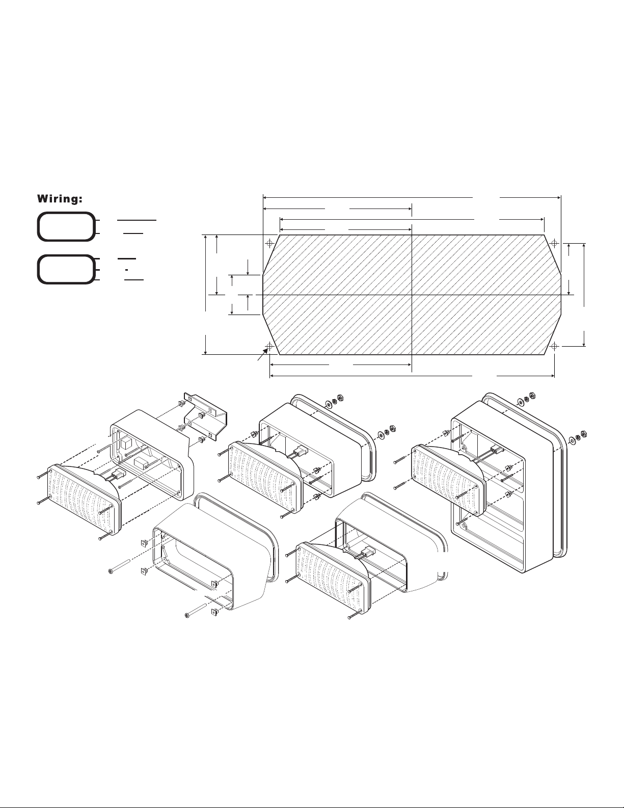
Installation:
3.438"
6.876"
.454"
.909"
1.380"
2.760"
1.188"
2.375"
3.281"
6.562"
3.050"
6.100"
1/4” Mounting
Hole (Qty. 4)
CUT-OUT and REMOVE THIS AREACUT-OUT and REMOVE THIS AREACUT-OUT and REMOVE THIS AREA
MOUNTING DIAGRAM / 700 SERIES HALOGEN LIGHTHEADMOUNTING DIAGRAM / 700 SERIES HALOGEN LIGHTHEAD
NOT TO SCALE / For reference only.NOT TO SCALE / For reference only.NOT TO SCALE / For reference only.
1. Using the measurements in the mounting diagram, mark off the 4 mounting holes and center cut-out.
2. Drill the 4 mounting holes and cut-out center area using the measurements shown here.
3. Attach the lighthead securely to the vehicle using the 4 Phillips head sheet metal screws and flange grommet supplied.
4. Extend the wires to their connections.
WARNING! All customer supplied wires that connect to the positive terminal of the battery must be sized to supply at least
125% of the maximum operating current and FUSED at the battery to carry the load. DO NOT USE CIRCUIT BREAKERS WITH
THIS PRODUCT!
IMPORTANT! Before returning this vehicle to active service, visually confirm the proper operation of this product, as well as all
vehicle components/equipment.
Page 2
Page 3

WARNING: Do not replace Halogen
Bulbs with ones of higher wattage
than (see Parts List).recommended
WARNING: Do not replace Halogen Bulbs with ones of higher wattage
than ( ee Parts List)recommended s .WARNING:
WATTAGE:
12V - 35W
12V - 50W
12V - 60W
12V - 27W
12V - 20W
12.8V - 14V, 27/12W
28V - 35W
0 =
1 =
2 =
3 =
4 =
5 =
6 =
CONNECTOR / CABLE
3 POS. 2 WIRE AMP CONN without CABLE
3 POS. 2 WIRE AMP CONN with CABLE
2 WIRE DEUTSCH CONN without CABLE
2 WIRE DEUTSCH CONN with CABLE
2 POS. AMP CONN without CABLE
3 POS. 3 WIRE AMP CONN without CABLE
3 POS. 3 WIRE AMP CONN with CABLE
3 WIRE DEUTSCH CONN without CABLE
3 WIRE DEUTSCH CONN with CABLE
0 =
1 =
2 =
3 =
4 =
5 =
6 =
7 =
8 =
WATTAGE
BASIC P/N
COLOR CONNECTOR & CABLE REQ.
01-0683709_ _ _
PART NUMBER KEY:
NOTE: If you have a
scene light lens, the
date stamp on the
lens must be located
on the top when
mounted.
9
8
8
7
6
5
4
2
3
2
1
1
1
1
1
0
9
700 SERIES HALOGEN LIGHTHEAD
, l , , Brake/ /Snap-In Style: Warning Scene ight Back-Up Tail Turn
LENS TYPE & COLOR
A=
R =
Q =
T =
AMBER OPTIC
RED OPTIC
RED ARROW
AMBER ARROW
CABLE & CONNECTOR
Without Cable / AMP CONNECTOR
With Cable & AMP CONNECTOR
Without Cable / DEUTSCH CONNECTOR
With Cable & DEUTSCH CONNECTOR
0 =
1 =
2 =
3 =
PART NO. KEY:
CABLE & CONNECTOR
BASIC P/N
LENS TYPE & COLOR
01-0683742-_ _
700 SERIES HALOGEN LIGHTHEAD
/Bayonet Style: Brake/Tail Turn
NOTE: Cables shown are
for reference only and are
not included.
NOTE: Cables shown are
for reference only and are
not included.
12
30
20
36
23
24
19
18
13
22
21
25 26 27
28 29 35
1
234
56
7
89
10
11
13
1
8
14
17
15
6
7
16
9210311 12
COLOR:
A=
B =
C =
G =
R =
=
5 =
Q =
T =
S =
AMBER
BLUE
CLEAR
GREEN
RED
SPLIT
KKKE-SPEC RED
RED ARROW
AMBER ARROW
SCENELIGHT
R
1
LABEL, 700 SERIES SCENELIGHT
10-0522890-04
1
MODEL 700 SCENELIGHT
01-06837090S_
MODEL 700 STOP/TAIL/TURN
01-06837095__
A/R
A/R
46-0742624-03
46-0742651-03
SNAP-IN CLIP (3 WIRE) WATERPROOF
SNAP-IN CLIP (3 WIRE)
A/R
A/R
A/R
A/R
4
1
1
1
A/R
A/R
1
1
1
A/R
A/R
A/R
4
A/R
A/R
1
1
1
A/R
1
1
A/R
A/R
1
1
10-0522890-03
LABEL, 700 SERIES STOP/TAIL/TURN
ASSY, LAMP, 12.8V-14V, 27/12W
34-0062389-00
LENS, RED ARROW W/ SEAL
68-1183529-5S
LENS, AMBER ARROW W/ SEAL
68-1183529-1S
LENS, SCENELIGHT W/ SEAL
68-1183464-3S
TAPE, STRAIN RELIEF
1
66-0422787-00
A/R
68-1183582E5S
LENS, KKKE-SPEC RED W/ SEAL
SNAP-IN CLIP (2 WIRE) 2 POS. AMP
46-0742684-01
A/R
A/R
A/R
34-0041987-04
34-0041987-03
ASSEMBLY, SNAP-IN LAMP (12V-27H)
ASSEMBLY, SNAP-IN LAMP (12V-20W)
10-0522890-02
1
22-0463039-00
HOUSING, RIGHT ANGLE CLIP DETAIL
02-0363417__S
A/R
LENS, SPLIT W/ SEAL
A/R
46-0742624-02
SNAP-IN CLIP (2 WIRE)
34-0041987-00
ASSEMBLY, SNAP-IN LAMP (12V-35W)
68-1183582-5S
LENS, RED W/ SEAL
68-1183582-4S
LENS, GREEN W/ SEAL
68-1183582-3S
LENS, CLEAR W/ SEAL
68-1183582-2S
LENS, BLUE W/ SEAL
A/R
1
1
1
1
A/R
A/R
A/R
A/R
A/R
4
01-0683709___
MODEL 700 HALOGEN
15-061416-240
#6 X 1 1/2" PHIL PAN HD SMS
68-1183582-1S
LENS, AMBER W/ SEAL
68-5983140-01
38-0463342-00
10-0320776-00
01-0440624-15
700 HALOGEN REFLECTOR
GASKET
MADE IN THE USA FLAG LABEL
LABEL, 700 SERIES HALOGEN
KIT, CABLEASSEMBLY
A/R
01-0442199-15
KIT, CABLEASSEMBLY (WATERPROOF)
A/R
46-0742651-02
SNAP-IN CLIP (2 WIRE) WATERPROOF
34-0041987-01
ASSEMBLY, SNAP-IN LAMP (12V-50W)
A/R
A/R
A/R
66-0716286-00
ADHESIVE GEL
A/R
66-0716886-00
PRIMER
ASSEMBLY, SNAP-IN LAMP (12V-60W)
34-0041987-07
A/R
34-0041987-02
A/R
ASSEMBLY, SNAP-IN LAMP (28V-35W)
4
1
1
1
1
1
1
A/R
A/R
1
1
1
01-06837093S0
MODEL 700 BACK-UP
11-76D257-000
1111
FLANGE GROMMET, 700 SERIES
2
3
11
26
12
27
13
28
14
29
15
30
16
31
17
32
18
33
19
34
20
35
4
5
6
21
7
22
8
23
9
24
10
25
1
ITEM PART NUMBER DESCRIPTION
QTY QTY QTYQTY
36
5
EPOXY
66-0716003-1C
11-76D257-000
FLANGE GROMMET, 700 SERIES
1
2
3
ITEM
PART NUMBER
DESCRIPTION
QTY
11
12
13
14
15
16
17
4
5
6
7
8
9
10
1
A/R
A/R
A/R
4
1
A/R
A/R
1
A/R
A/R
A/R
A/R
A/R
A/R
1
A/R
SOCKET ASS'Y AMP,
REFLECTOR TAIL TURN 700 SERIES, STOP/ / ,
MODEL 700 SERIES TAIL TURN, STOP/ /
SCREW #6 X 1-1/2" PPHSMS,
LENS MODEL 700 SERIES ARROW RED,,
LENS MODEL 700 SERIES RED,,
SOCKET ASS'Y DEUTSCH,
DEUTSCH 3 POS SOCKET WEDGE
DEUTSCH 3 POS SOCKET CONNECTOR
LENS MODEL 700 SERIES AMBER,,
LAMP TAIL TURN #1157, STOP/ /
3 POS PIN HOUSING
LENS MODEL 700 SERIES ARROW AMBER,,
KIT CABLE ASS Y WATERPROOF,',
KIT CABLE ASS Y AMP,',
GASKET MOLDED MODEL 700,,
38-0463342-00
01-0442199-15
01-0440624-15
33-0517116-02
68-5983700-01
39-1H16424-3S
39-1H03024-35
68-1183582-1S
68-1183582-5S
34-0021562-00
33-0517116-01
39-0403013-04
15-061416-240
01-0683742-__
68-1183529-1S
68-1183529-5S
Page 3
 Loading...