

Page 1

®
ENGINEERING COMPANY INC.
51 Winthrop Road
Chester, Connecticut 06412-0684
700 Series LED Lighthead
Installation Guide:
Phone: (860) 526-9504
Fax: (860) 526-4078
Internet: www.whelen.com
Sales e-mail: autosale@whelen.com
Canadian Sales e-mail: canadiansales@whelen.com
Customer Service e-mail: custserv@whelen.com
Safety First
This document provides all the necessary information to allow your Whelen product to be properly and safely installed.
Before beginning the installation and/or operation of your new product, the installation technician and operator must
read this manual completely. Important information is contained herein that could prevent serious injury or damage.
• Proper installation of this product requires the installer to have a good understanding of automotive electronics,
systems and procedures.
• Failure to use specified installation parts and/or hardware will void the product warranty!
• If mounting this product requires drilling holes, the installer MUST be sure that no vehicle components or other
vital parts could be damaged by the drilling process. Check both sides of the mounting surface before drilling
begins. Also de-burr any holes and remove any metal shards or remnants. Install grommets into all wire
passage holes.
• If this manual states that this product may be mounted with suction cups, magnets, tape or Velcro®, clean the
mounting surface with a 50/50 mix of isopropyl alcohol and water and dry thoroughly.
• Do not install this product or route any wires in the deployment area of your air bag. Equipment mounted or
located in the air bag deployment area will damage or reduce the effectiveness of the air bag, or become a
projectile that could cause serious personal injury or death. Refer to your vehicle owner’s manual for the air bag
deployment area. The User/Installer assumes full responsibility to determine proper mounting location, based
on providing ultimate safety to all passengers inside the vehicle.
• For this product to operate at optimum efficiency, a good electrical connection to chassis ground must be
made. The recommended procedure requires the product ground wire to be connected directly to the NEGATIVE
(-) battery post.
• If this product uses a remote device to activate or control this product, make sure that this control is located in
an area that allows both the vehicle and the control to be operated safely in any driving condition.
• Do not attempt to activate or control this device in a hazardous driving situation.
• This product contains either strobe light(s), halogen light(s), high-intensity LEDs or a combination of these
lights. Do not stare directly into these lights. Momentary blindness and/or eye damage could result.
• Use only soap and water to clean the outer lens. Use of other chemicals could result in premature lens cracking
(crazing) and discoloration. Lenses in this condition have significantly reduced effectiveness and should be
replaced immediately. Inspect and operate this product regularly to confirm its proper operation and mounting
condition. Do not use a pressure washer to clean this product.
• It is recommended that these instructions be stored in a safe place and referred to when performing
maintenance and/or reinstallation of this product.
• FAILURE TO FOLLOW THESE SAFETY PRECAUTIONS AND INSTRUCTIONS COULD RESULT IN DAMAGE TO
THE PRODUCT OR VEHICLE AND/OR SERIOUS INJURY TO YOU AND YOUR PASSENGERS!
Automotive: Lightheads
For warranty information regarding this product, visit www.whelen.com/warranty
©2001 Whelen Engineering Company Inc.
Form No.13570N (121311)
Page 1
Page 2
CAUTION! DO NOT LOOK DIRECTLY AT
THESE LEDS WHILE THEY ARE ON.
MOMENTAR Y BLINDNESS AND/OR EYE
DAMAGE COULD RESULT!
IMPORTANT WARNING!
IMPORTANT NOTICE!This product has been designed for improved visibility. Prior to installing
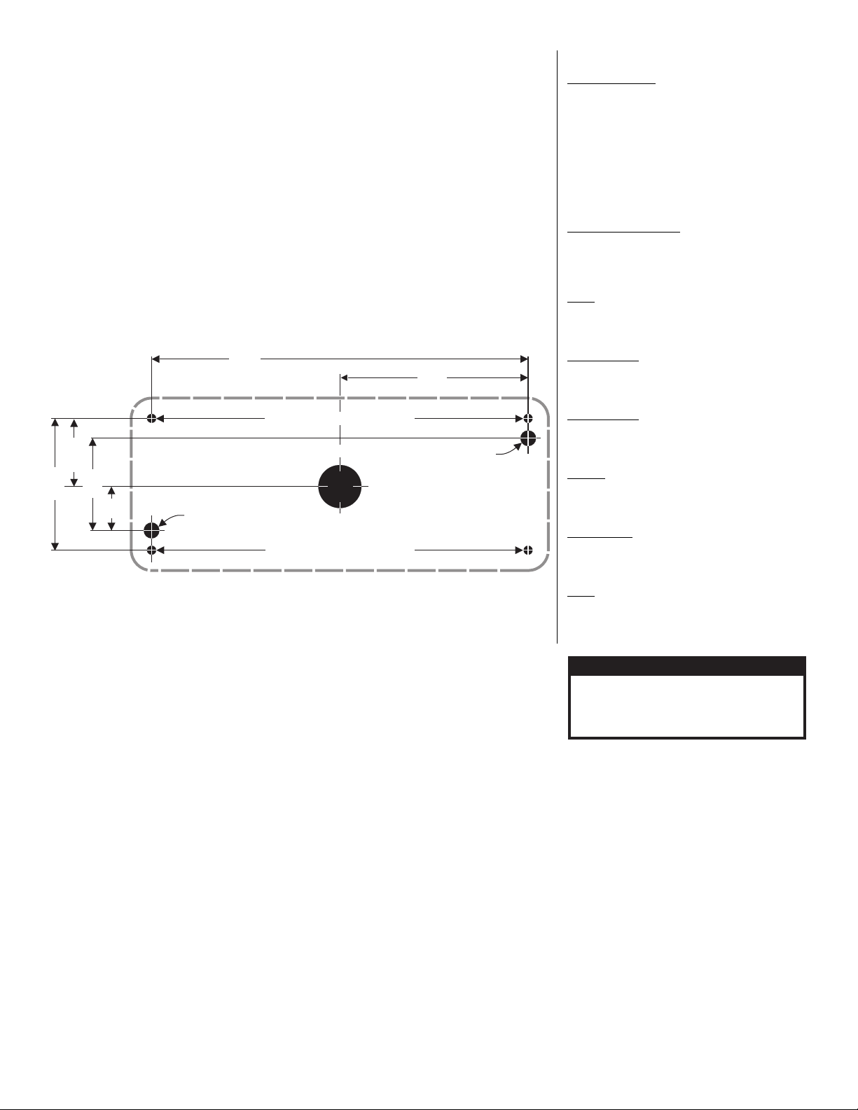
3.281"
6.562"
5/16"
5/16"
Diameter
Diameter
Vent Hole
Vent Hole
1.187"
1.68"
.84"
2.375"
700 SERIES LED LIGHTHEAD
MOUNTING DIMENSIONS
NOT TO SCALE / FOR MEASUREMENTS ONLY
1/4" Mounting Hole / 4 Places
1/4" Mounting Hole / 4 Places
1"
Wire
Hole
this product on any vehicle, check your state motor vehicle codes to confirm that this product
complies with any and all state statutes.
Mounting:
1. Using the dimensions below, mark off and drill the two, 5/16” diameter vent tube holes and the 1”
wire hole into the mounting surface. Make sure lighthead will not interfere with existing equipment
and be aware of any items on the opposite side of the mounting surface.
IMPORTANT WARNING: Always check all measurements before drilling. Measurements are
given in both decimals and fractions for your convenience. For a more accurate measurement
and installation, use the decimals.
2. Insert the two vent tubes extending from the rear of the lighthead into their holes. Using a scribe or
similar tool, mark off the 4 mounting holes.
3. Using a 1/4” drill bit, drill the four mounting holes. Install a grommet (customer supplied) into the 1”
wire hole.
4. Using appropriately sized wires (minimum 18 AWG wire size), extend the lighthead wires to their
connections (see “Wiring Options”). Fuse the +12VDC connections at 3 Amps and test the lighthead
before securing it to the vehicle.
Note:Some 700 series lightheads are equipped with the SYNC feature. These lightheads will
have an extra grey wire (See below).
5. Position the lighthead components onto the mounting surface and secure to the vehicle using the
flange grommet and four supplied #6 x 1-1/4” sheet metal screws.
WARNING!
automotive bulb. If your flasher does not operate properly, it may be necessary to replace your
existing flasher module with a Whelen® 3TERM flasher module. Contact your sales
representative for specific vehicle application.
WARNING! All customer supplied wires that connect to the positive terminal of the battery must
be sized to supply at least 125% of the maximum operating current and FUSED at the battery to
carry the load. DO NOT USE CIRCUIT BREAKERS WITH THIS PRODUCT!
IMPORTANT! Before returning this vehicle to active service, visually confirm the proper operation
of this product, as well as all vehicle components/equipment.
This product draws significantly less current than a standard incandescent
Specifications:
BRAKE/TAIL/TURN
LED Assembly - 120 LEDs (MAX)
Input Voltage - 12.8 VDC ±20%
Input Current - Tail - 0.125 Amps
Default Pattern - SignalAlert™ Brake
LED Assembly - 56 LEDs (MIN)
Input Voltage - 12.8 VDC ±20%
Input Current - Tail - 0.075 Amps
Default Pattern - SignalAlert™ Brake
WIDE ANGLE WARNING
Input Voltage - 12.8 VDC ±20%
Input Current - 0.40 Amps (Blue / White / Green)
Default Pattern - RapidFire™ 375
TURN
Input Voltage - 12.8 VDC ±20%
Input Current - 0.70 Amps
Default Pattern - SignalAlert™ Brake
BACK-UP (12V)
Input Voltage - 12.8 VDC ±20%
Input Current - 0.300 Amps
Default Pattern - Steady On
BACK-UP (24V)
Input Voltage - 25.6 VDC ±20%
Input Current - 0.150 Amps
Default Pattern - Steady On
ARROW
Input Voltage - 12.8 VDC ±20%
Input Current - 0.475 Amps
Default Pattern - Steady
DUAL COLOR
Input Voltage - 12.8 VDC ±20%
Input Current - 0.475 Amps
Default Pattern - RapidFire™ 680
SYNC
Input Voltage - 12.8 VDC ±20%
Input Current - 0.475 Amps
Default Pattern - SignalAlert™ (Simultaneous)
- Brake - 0.70 Amps
- Brake - 0.375 Amps
- 0.45 Amps (Amber / Red)
Flash Pattern Synchronization (SYNC):
A SYNC feature is available on selected models. This allows two (or more)
lightheads to flash the same, synchronized pattern in either simultaneous or
alternating mode. In order to enable SYNC mode, it is necessary for the
GREY wires from each lighthead to be connected together.
There is only one pattern available to a SYNC-capable lighthead, offering
both a simultaneous and alternating mode:
SignalAlert™ 75 Simultaneous mode - 75 fpm (Factory Default)
SignalAlert™ 75 Alternating mode - 75 fpm
To help understand how to use SYNC, the principals will be applied to a
sample system consisting of 4 lightheads, with 2 mounted on the rear, driver
side of the vehicle and 2 mounted on the rear, passenger side.
With all the wiring complete, turn on the 4 lightheads. As shipped from the
factory, all the lightheads will be flashing simultaneously.
To configure, for example, the passenger side lightheads to alternate with
the driver side lightheads, change the flash patterns for either the passenger
or driver side lightheads to Alternating.
Important! SYNC-capable LED lightheads can be SYNCed to SYNCcapable strobe power supplies (such as the CS240S) by wiring their grey
wires together. When connected as such, LED lightheads in their default
pattern (simultaneous) will flash simultaneously with strobe lightheads
connected to the GREEN wire outputs. LED lightheads configured for the
alternating pattern will flash simultaneously with strobe lightheads connected
to the WHITE wire outputs. GREEN wire outputs always alternate with
WHITE wire outputs.
Page 2
Page 3
Scan-Lock™ (White/Violet)
See next page for parts listings.
ARROW
..........
...Ground
....Scan Lock
LED Color
Black(12V
) or
Black-White(24V
)
White-Violet - ™
Positive(+
)
NOTE: In some instances two
ground wires are shown for
reference. This is to show
both the 12 volt and 24 volt
models. The lighthead will
have either one or the other
depending on model.
..........Positive(+
)
............................SYNC
...............
Ground
SYNC
LED Color
Grey
Black(12V
)
BRAKE-TAIL-TURN
....Brake Positive(+
)
........Tail Positive(+
)
...Ground
.....Scan Lock
Yellow /
Brown /
White(12V
) or
White-Black(24V
)
White-Violet - ™
..........Positive(+
)
...Ground
.....Scan Lock
TURN
LED Color
Black(12V
) or
Black-White(24V
)
White-Violet - ™
.......Positive(+
)
.......Positive(+
)
........................Ground
SPLIT
LED Color 1
LED Color 2
Black
MAX BIAS
..........Positive(+
)
...Ground
LED Color
Black(12V
) or
Black-White(24V
)
FLOOD or BACK-UP
..................Positive(+
)
...Ground
White
Black(12V
) or
Black-White(24V
)
..........Positive(+
)
..Ground
......Scan Lock
WIDE ANGLE
LED Color
Black(+12V
) or
Black-White(24V
)
White-Violet - ™
2 3 4
12
58 64
26144516341836
20
38
284029
13
59 65
44
15
3317351937
27
1
10 11 399
7 85 6
21 23 25 41 4322 24 30 42 46 6150 6349 6257 66
47
51 53 54
48
52
55
56
Housing (w/studs):
Housing:
Mounting Hardware & Gasket:
11-483530-011
11-483530-111
01-0483596-00
For use with:
HALOGEN, STROBE
or LED lightheads
Lighthead Housing:
Drivers Side:
Passengers Side:
01-0462735-01
01-0462736-01
For use with:
HALOGEN, STROBE
or LED lightheads
Surface Mount Housing:
Black:
Chrome:
01-0464758-00
01-0464758-01
For use with:
HALOGEN, STROBE
or LED lightheads
For use with:
HALOGEN, STROBE
or LED lightheads
Available Mounting Options
Wiring Options
Parts
Housing:
Housing w/Studs:
Mounting Hardware & Gasket:
11-463255-011
11-463255-111
01-0463331-00
Mini-Grill-Master Housing:
Black:
Chrome:
01-0483777-01
01-0483777-02
For use with: STROBE
or LED lightheads
For use with: LED lightheads
Flange Kit: Without Seal
With Seal
01-0462920-00
01-0462920-01
Swivel Mount Kit:
Black:
Chrome:
11-481138-00
01-0441293-00
32
67
WARNING: Pattern selection requires the LEDs to be turned on. Do not
look directly at the LEDs while the unit is on.
TO CHANGE PATTERNS: Apply +VBAT to the WHITE/VIOLET wire for less
than 1 second and release to cycle forward to the next available pattern.
Apply +VBAT to the WHITE/VIOLET wire for more than 1 second and
release to cycle back to the previous pattern. Allow the pattern to run for
more than 5 seconds to set as the default pattern.
TO RESTORE FACTORY DEFAULT PATTERN: With the power to the
lighthead off, apply +VBAT to the WHITE/VIOLET wire. Now turn power to
the lighthead on. The factory default pattern should now be displayed.
A Normally Open momentary switch can be used to control Scan-Lock.
IMPORTANT SPLIT LED NOTE: This lighthead will not have a Scan-Lock™
wire. You will find 2 sets of programming pins protruding from the LED side
of the circuit board. Where the Scan-Lock instructions say “apply +12 volts to
the Scan-Lock wire”, short the pins out with a penny (or other electrical
conducting item). For a Split SMT LED lighthead, there will be 2 sets of
programming pins. Both sides can be programmed separately using the
same procedure as a regular LED lighthead.
Flash Patterns:
1. SignalAlert™ 75
2. SignalAlert 150
3. SingleFlash 375
4. SingleFlash 150
5. SingleFlash 75
6. SingleFlash 150
7. DoubleFlash 150
8. DoubleFlash 75
9. CometFlash® 75
10. ActionFlash™
11. ModuFlash™
12. ComAlert™
13. ActionScan™
14. SignalAlert Steady
15. Steady (Brake)
Brake Patterns:
1. SignalAlert Steady
2. Steady Brake
SYNC Patterns:
1. SignalAlert 75 (Sim.)
2. SignalAlert 75 (Alt.)
Arrow Patterns:
1. Seq. to Solid 150
2. Seq. to Solid 80
3. Seq. to Solid (Steady On - Fast)
4. Seq. to Solid (Steady On - Slow)
5. SignalAlert to Steady On
6. Steady On
Dual Color Patterns:
1. SingleFlash 680 (Alt.)
2. SingleFlash 240 (Alt.)
3. SingleFlash 120 (Alt.)
4. SingleFlash 150 (Sim.)
5. DoubleFlash 240 (Alt.)
6. DoubleFlash 120 (Alt.)
7. DoubleFlash 150 (Sim.)
8. CometFlash® 120 (Alt.)
9. CometFlash 120 (Sim.)
10. ActionFlash (Alt.)
11. ActionFlash (Alt. - Sim.)
12. ModuFlash (Alt.)
13. ModuFlash (Sim.)
14. SignalAlert 120 (Alt.)
15. SignalAlert 100 (Sim.)
16. ActionScan (Alt. - Sim.)
17. Action Single
18. CH.1 Steady-CH.2 SF120
19. CH.1 Steady-CH.2 Action Single
20. CH.1 Steady-CH.2 CometFlash
21. CH.1 Steady-CH.2 FastAction
Page 3
Page 4

TERMINATION
0 =
1 =
2 =
NONE
DEUTSCH
AMP PIMS WITH 3
PIN CONNECTOR
SHIPPED
SEPERATELY
2 =
2 =
2 =
PART NUMBER KEY:
STYLE
TERMINATION
01-0683718___
STYLE
2 =
3 =
4 =
5 =
6 =
7 =
B =
S =
A=
L=
K =
D =
N =
B-T-T / MIN
ARROW
TURN
WIDE ANGLE / SPLIT
FLOOD
BACK-UP
B-T-T / MAX
24V B-T-T / MAX
BACK-UP (24V)
SYNC
MAX BIAS
TURN (24V)
WIDE ANGLE (24V)
MAX BIAS (24V)
B-T-T (CERTIFIED)
E =
G =
LED-LENS COLOR
A=
B =
C =
G =
R =
D =
J =
1 =
2 =
4 =
5 =
=
=
W =
6 =
7 =
8 =
AMBER-AMBER
BLUE-BLUE
WHITE-CLEAR
GREEN-GREEN
RED-RED
RED-WHT / RED-CLR
RED-BLUE / RED-BLU
AMBER-CLEAR
BLUE-CLEAR
GREEN-CLEAR
RED-CLEAR
AMB-AMB-AMB
RED-AMB / RED-AMB
RED / RED / RED
AMB / AMB / CLEAR
RED / AMB / CLEAR
RED / RED / CLEAR
S
K
LED/LENS COLOR
68-1183582-5S
LENS, RED OPTIC W/ SEAL
68-1183582-4S
LENS, GREEN OPTIC W/ SEAL
68-1183582-3S
LENS, CLEAR OPTIC W/ SEAL
68-1183582-2S
LENS, BLUE OPTIC W/ SEAL
68-1183582-1S
LENS, AMBER OPTIC W/ SEAL
LIGHTHEAD 700 LED WIDE ANGLE
01-06837185_0
01-06837182R0
01-0683718BR0
01-06837184_0
01-06837186C_
01-06837187C_
01-06837183__
LIGHTHEAD 700 LED TURN
LIGHTHEAD 700 LED FLOOD - WHITE
LIGHTHEAD 700 LED BACK-UP - WHITE
LIGHTHEAD 700 LED ARROW
LIGHTHEAD 700 LED BRAKE/TAIL/TURN (MIN) - RED
LIGHTHEAD 700 LED BRAKE/TAIL/TURN (MAX) - RED
15-061416-240
68-3183573-1S
68-3183573-3S
68-3183573-5S
02-0363417RBS
01-0283461-52
01-0283461-15
01-0283461-25
01-0283461-45
01-0283461-55
01-0283461-5B
01-0283461-35
01-0283461-14
01-0283461-54
01-0283461-36
01-0283461-37
01-0283461-13
01-0283461-53
01-0283461-J5
38-0463342-00
10-0522894___
SCREW, #6 X 1-1/2" PPHSMS
LENS, AMBER W/ SEAL
LENS, CLEAR W/ SEAL
LENS, RED W/ SEAL
LENS, RED/BLUE OPTIC W/ SEAL
SUB ASSY, 700 LED BRAKE/TAIL/TURN (MIN)
SUB ASSY, 700 LED WIDE ANGLE - AMBER
SUB ASSY, 700 LED WIDE ANGLE - BLUE
SUB ASSY, 700 LED WIDE ANGLE - GREEN
SUB ASSY, 700 LED WIDE ANGLE - RED
SUB ASSY, 700 LED BRAKE/TAIL/TURN (MAX)
SUB ASSY, 700 LED WIDE ANGLE - WHITE
SUB ASSY, 700 LED TURN - AMBER
SUB ASSY, 700 LED TURN - RED
SUB ASSY, 700 LED FLOOD - WHITE
SUB ASSY, 700 LED BACK-UP - WHITE
SUB ASSY, 700 LED ARROW - AMBER
SUB ASSY, 700 LED ARROW - RED
SUB ASSY, 700 LED WIDE ANGLE - RED/BLUE
GASKET
LABEL, 700 SERIES LED LIGHTHEAD
02-0363417RCS
LENS, RED/CLEAR OPTIC W/ SEAL
01-0283461-D5
01-06837185_1
01-0683718BR1
LIGHTHEAD 700 LED BRAKE/TAIL/TURN (MAX) - RED/DEUTSCH
LIGHTHEAD 700 LED WIDE ANGLE - DEUTSCH
02-0383461115
02-038346115B
SUB ASSY, 700 LED WIDE ANGLE - AMBER/DEUTSCH
SUB ASSY, 700 LED BRAKE/TAIL/TURN (MAX) - RED/DEUTSCH
LIGHTHEAD 700 LED SYNC
01-0683718S_0
01-0283461-1S
SUB ASSY, 700 LED SYNC - AMBER
01-0283461-5S
SUB ASSY, 700 LED SYNC - RED
01-0283461-2S
SUB ASSY, 700 LED SYNC - BLUE
01-0283461-3S
SUB ASSY, 700 LED SYNC - WHITE
01-0283461-4S
SUB ASSY, 700 LED SYNC - GREEN
01-0283461-A5
SUB ASSY, 700 LED SPLIT - AMBER/AMBER
01-0283461-K5
SUB ASSY, 700 LED SPLIT - RED/AMBER
01-0283461-R5
SUB ASSY, 700 LED SPLIT - RED/RED
LENS, RED/AMBER OPTIC W/ SEAL
02-0363417RAS
02-0383461125
SUB ASSY, 700 LED WIDE ANGLE - BLUE/DEUTSCH
LIGHTHEAD 700 LED BRAKE/TAIL/TURN (MIN) - RED/DEUTSCH
01-06837182R1
02-0383461152
SUB ASSY, 700 LED B-B-T (MIN) - RED/DEUTSCH
SUB ASSY, 700 LED WIDE ANGLE - RED/WHITE
SUB ASSY, 700 LED FLOOD - WHITE/DEUTSCH
02-0383461136
01-0683718E__
LIGHTHEAD 700 LED 24V BRAKE/TAIL/TURN (MAX) - RED
SUB ASSY, 700 LED 24V BRAKE/TAIL/TURN (MAX)
01-0283461-5E
02-0383461137
SUB ASSY, 700 LED BACK-UP - WHITE/DEUTSCH
02-038346113G
SUB ASSY, 700 LED 24V BACK-UP - WHITE/DEUT
02-038346115E
SUB ASSY, 700 LED 24V B-T-T (MAX) - RED/DEUTSCH
01-0683718A_0
01-0683718L_0
01-0683718K__
01-0683718D_0
LIGHTHEAD 700 LED MAX BIAS
LIGHTHEAD 700 LED TURN 24V
LIGHTHEAD 700 LED WIDE ANGLE 24V
LIGHTHEAD 700 LED MAX BIAS 24V
SUB ASSY, 700 LED MAX BIAS - AMBER
01-0283461-1A
01-0283461-5A
SUB ASSY, 700 LED MAX BIAS - RED
01-0283461-1L
SUB ASSY, 700 LED TURN 24V - AMBER
01-0283461-5L
SUB ASSY, 700 LED TURN 24V - RED
01-0283461-1K
SUB ASSY, 700 LED WIDE ANGLE 24V - AMBER
01-0283461-5K
SUB ASSY, 700 LED WIDE ANGLE 24V - RED
01-0283461-1D
SUB ASSY, 700 LED MAX BIAS 24V - AMBER
01-0283461-5D
SUB ASSY, 700 LED MAX BIAS 24V - RED
01-0683718GC1
LIGHTHEAD 700 LED 24V BACK-UP - WHITE/DEUTSCH
02-038346115K
02-038346111K
SUB ASSY, 700 LED WIDE ANGLE 24V - AMB/DEUTSCH
SUB ASSY, 700 LED WIDE ANGLE 24V - RED/DEUTSCH
01-0683718NR0
LIGHTHEAD 700 LED B/T/T CERTIFIED
01-0283461-5N
SUB ASSY, 700 LED B/T/T CERTIFIED - RED
SUB ASSY, 700 LED ARROW - AMBER/DEUTSCH
02-0383461153
02-0383461113
SUB ASSY, 700 LED ARROW - RED/DEUTSCH
39-0403013-04
HOUSING, 3 POS. PIN, AMP
02-038346155B
02-0383461552
02-0383461537
02-0383461514
02-0383461513
02-03834615_5
SUB ASSY, 700 LED B-T-T(MAX) AMP PINS ONLY
SUB ASSY, 700 LED (MIN) AMP PINS ONLYB-T-T
SUB ASSY, 700 LED BACK UP, WHT AMP PINS ONLY
SUB ASSY, 700 LED TURN, AMP PINS ONLY
SUB ASSY, 700 LED ARROW, AMP PINS ONLY
SUB ASSY, 700 LED WIDE ANGLE, AMP PINS ONLY
01-0683718BR2
LIGHTHEAD 700 LED BRAKE/TAIL/TURN (MAX) - AMP PINS
LIGHTHEAD 700 LED BRAKE/TAIL/TURN (MIN) - AMP PINS
LIGHTHEAD 700 LED BACK UP - WHITE, AMP PINS
LIGHTHEAD 700 LED TURN, AMP PINS
LIGHTHEAD 700 LED ARROW,AMP PINS
LIGHTHEAD 700 LED WIDE ANGLE - AMP PINS
01-06837182R2
01-06837187C2
01-06837184A2
01-06837183A2
01-06837185_2
11-76D257-000
4
1
1
1
1
1
4
A/R
1
A/R
1
A/R
A/R
A/R
A/R
1
4
A/R
1
A/R
1
A/R
A/R
1
A/R
A/R
A/R
A/R
A/R
4
1
A/R
1
A/R
A/R
A/R
A/R
A/R
A/R
A/R
A/R
A/R
A/R
A/R
1
4
1
1
1
A/R
A/R
1
1
4
1
1
A/R
A/R
1
4
1
1
1
1
1
4
A/R
A/R
A/R
A/R
A/R
1
1
A/R
A/R
A/R
A/R
A/R
1
1
A/R
A/R
A/R
4
A/R
A/R
A/R
A/R
A/R
A/R
A/R
1
1
4
1
1
1
4
1
1
1
1
4
A/R
A/R
1
1
A/R
A/R
1
1
4
1
1
1
1
4
1
1
A/R
A/R
A/R
A/R
1
4
1
1
A/R
A/R
A/R
A/R
1
4
1
1
A/R
A/R
A/R
A/R
A/R
A/R
1
4
1
1
A/R
A/R
A/R
A/R
1
4
1
1
1
1
1
1
4
1
1
-
A/R
1
1
4
1
1
1
A/R
1
1
4
1
1
-
-
A/R
1
1
4
1
A/R
A/R
1
A/R
1
1
4
1
A/R
1
A/R
A/R
1
FLANGE GROMMET, 700 SERIES
1
4
1
1
A/R
A/R
A/R
A/R
A/R
A/R
1
A/R
A/R
2
3
11
12
13
14
15
16
17
18
19
20
4
5
6
7
8
9
10
1
21
22
30
31
32
33
34
35
36
37
38
39
23
24
25
26
27
28
29
40
41
49
50
51
52
53
54
55
56
57
58
42
43
44
45
46
47
48
ITEM
DESCRIPTION
QTY QTY QTY QTYQTYQTYQTYQTYQTYQTYQTYQTYQTYQTYQTYQTYQTYQTYQTY QTY QTY QTYQTYQTY
59
60
61
62
63
64
65
66
67
PART NUMBER
Page 4
 Loading...