

Page 1

®
ENGINEERING COMPANY INC.
51 Winthrop Road
Chester, Connecticut 06412-0684
Phone: (860) 526-9504
Installation Guide:
700 Series
Super-LED® Lighthead
Fax: (860) 526-4078
Internet: www.whelen.com
Sales e-mail: autosale@whelen.com
Canadian Sales e-mail: canadiansales@whelen.com
Customer Service e-mail: custserv@whelen.com
Safety First
This document provides all the necessary information to allow your Whelen product to be properly and safely installed.
Before beginning the installation and/or operation of your new product, the installation technician and operator must
read this manual completely. Important information is contained herein that could prevent serious injury or damage.
• Proper installation of this product requires the installer to have a good understanding of automotive electronics,
systems and procedures.
• Failure to use specified installation parts and/or hardware will void the product warranty!
• If mounting this product requires drilling holes, the installer MUST be sure that no vehicle components or other
vital parts could be damaged by the drilling process. Check both sides of the mounting surface before drilling
begins. Also de-burr any holes and remove any metal shards or remnants. Install grommets into all wire
passage holes.
• If this manual states that this product may be mounted with suction cups, magnets, tape or Velcro®, clean the
mounting surface with a 50/50 mix of isopropyl alcohol and water and dry thoroughly.
• Do not install this product or route any wires in the deployment area of your air bag. Equipment mounted or
located in the air bag deployment area will damage or reduce the effectiveness of the air bag, or become a
projectile that could cause serious personal injury or death. Refer to your vehicle owner’s manual for the air bag
deployment area. The User/Installer assumes full responsibility to determine proper mounting location, based
on providing ultimate safety to all passengers inside the vehicle.
• For this product to operate at optimum efficiency, a good electrical connection to chassis ground must be
made. The recommended procedure requires the product ground wire to be connected directly to the NEGATIVE
(-) battery post.
• If this product uses a remote device to activate or control this product, make sure that this control is located in
an area that allows both the vehicle and the control to be operated safely in any driving condition.
• Do not attempt to activate or control this device in a hazardous driving situation.
• This product contains either strobe light(s), halogen light(s), high-intensity LEDs or a combination of these
lights. Do not stare directly into these lights. Momentary blindness and/or eye damage could result.
• Use only soap and water to clean the outer lens. Use of other chemicals could result in premature lens cracking
(crazing) and discoloration. Lenses in this condition have significantly reduced effectiveness and should be
replaced immediately. Inspect and operate this product regularly to confirm its proper operation and mounting
condition. Do not use a pressure washer to clean this product.
• It is recommended that these instructions be stored in a safe place and referred to when performing
maintenance and/or reinstallation of this product.
• FAILURE TO FOLLOW THESE SAFETY PRECAUTIONS AND INSTRUCTIONS COULD RESULT IN DAMAGE TO
THE PRODUCT OR VEHICLE AND/OR SERIOUS INJURY TO YOU AND YOUR PASSENGERS!
Automotive: Lightheads
For warranty information regarding this product, visit www.whelen.com/warranty
©2004 Whelen Engineering Company Inc.
Form No.13901M (051414)
Page 1
Page 2
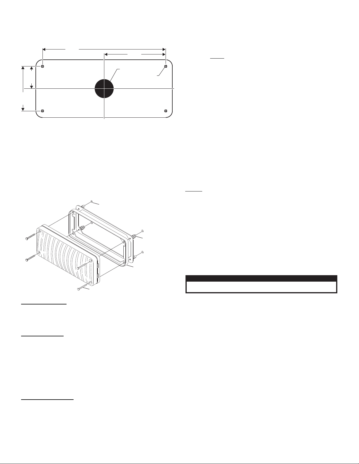
3.281"
2.375"
1.187"
6.562"
1" diameter hole
1/4" mounting hole
(4 places)
Installation:
CAUTION! DO NOT LOOK DIRECTLY AT THESE LED’S WHILE THEY ARE ON.
MOMENTARY BLINDNESS AND/OR EYE DAMAGE COULD RESULT!
IMPORTANT WARNING!
SCREW, 6 X 1-1/2" PPHSMS SS
GASKET
FLANGE GROMMET
700 SERIES
1/4" MOUNTING HOLE (4)
IMPORTANT! It is the responsibility of the installation technician to make sure
that the installation and operation of this product will not interfere with or
compromise the operation or efficiency of any vehicle equipment!
Caution: Permanent mounting of this product will require drilling. It is
absolutely necessary to make sure that no other vehicle components could be
damaged by this process. Check both sides of the mounting surface before
starting. If damage is likely, select a different mounting location.
1. Using the dimensions shown, mark off and drill the four 1/4” diameter mounting
holes and the 1” wire hole into the mounting surface. Check measurements
before drilling.
2. Install the flange grommet into the mounting holes then install a rubber
grommet (customer supplied) into the wire hole.
3. Using appropriately sized wires (minimum 18 AWG wire), extend the lighthead
wires to their appropriate connections. Fuse the positive connections at 3
Amps and test operation of lighthead before securing it to vehicle.
4. Position the lighthead onto the mounting surface and secure to the vehicle
using the four supplied #6 x 1-1/2” sheet metal screws.
Wiring:
WARNING! All customer supplied wires that connect to the positive terminal
of the battery must be sized to supply at least 125% of the maximum operating
current and FUSED
BREAKERS WITH THIS PRODUCT!
The 700 Series lighthead offers the user various features depending on the model.
Refer to the next page for wire designations and replacement parts.
Scan-Lock™ (White/Violet):
Note that the lighthead must be on to use the Scan-Lock™ feature except
where noted.
To advance to the next flash pattern - Apply +12VDC to the WHT/VIO wire for less
than 1 second and release.
To cycle backwards through the flash patterns - Apply +12VDC to the WHT/VIO
wire for more than 1 second and release.
To reset to the factory default flash pattern - Turn off power to the lighthead. While
applying +12VDC to the WHT/VIO wire, turn power to the lighthead on. Continue to
apply voltage to the WHT/VIO wire for 5 seconds. The default pattern will now be
active.
NOTE: A Normally Open momentary switch is suggested to activate the ScanLock™ wire.
SYNC (Grey) - To SYNC two lightheads, configure both lightheads to display the
same Phase 1 pattern. With the power off, connect the Grey wires from each
lighthead. When the lightheads are activated, their patterns will be synchronized. To
configure the two lightheads to alternate their patterns, advance the pattern of either
lighthead to the Phase 2 mode of the current pattern. Remember, Phase 1 patterns
alternate with Phase 2 patterns!
ALWAYS
Hi/Low Intensity (Violet) - This feature allows the user to step the unit down to low
power operation for nighttime use. Apply positive voltage to the VIOLET wire to put
the lighthead into low power. Remove the voltage from the VIOLET wire to restore
normal high power operation.
The table below provides wiring information for the 700 Series lighthead. Refer to the
appropriate flash pattern list as determined by the lighthead style:
WARNING! The LED models designated “Steady” must be connected to an
electronic flasher. Allowing the LED to steady burn will damage the lighthead
and void the warranty.
standard incandescent automotive bulb. If your flasher does not operate
properly, it may be necessary to replace your existing flasher module with a
Whelen 3TERM flasher module. Contact your sales representative for specific
vehicle application.
at the battery to carry that load. DO NOT USE CIRCUIT
This product draws significantly less current than a
SYNC Pattern Table:
Sync-Capable Flash Patterns:
1. SignalAlert™ 75 - Phase 1
2. SignalAlert 75 - Phase 2
3. CometFlash® 75 - Phase 1
4. CometFlash 75 - Phase 2
5. DoubleFlash 75 - Phase 1
6. DoubleFlash 75 - Phase 2
7. SingleFlash 75 - Phase 1
8. SingleFlash 75 - Phase 2
9. ComAlert™ 75 - Phase 1
10. ComAlert 75 - Phase 2
11. LongBurst™ 75 - Phase 1
Split Pattern Table:
14. PingPong 75 - SIM*
15. SSNF 75
16. SingleFlash 60 - ALT
17. SingleFlash 60 - SIM
18. SingleFlash 90 - ALT*
19. SingleFlash 90 - SIM*
20. SingleFlash 120 - ALT*
21. SingleFlash 120 - SIM*
22. SingleFlash 300 - ALT
23. SingleFlash 300 - SIM
24. DoubleFlash 150 - ALT
25. DoubleFlash 150 - SIM
26. ComAlert™ 150 - ALT
4. SingleFlash 150
5. SingleFlash 75*
6. DoubleFlash 150
1. SignalAlert™ 75 - ALT
2. SignalAlert 75 - SIM
3. CometFlash 75 - ALT
4. CometFlash 75 - ALT
5. DoubleFlash 75 - ALT*
6. DoubleFlash 75 - SIM*
7. SingleFlash 75 - ALT*
8. SingleFlash 75 - ALT*
9. ComAlert™ 75 - ALT
10. ComAlert 75 - SIM
11. LongBurst™ 75 - ALT
12. LongBurst 75 - SIM
13. PingPong™ 75 - ALT*
Standard Pattern Table:
1. SignalAlert™75
2. SignalAlert150
3. SingleFlash 375
IMPORTANT! Before returning the vehicle to active service, visually confirm the proper operation of this product, as well as all vehicle
components/equipment.
12. LongBurst 75 - Phase 2
13. PingPong™ 75 - Phase 1
14. PingPong 75 - Phase 2
Non-Sync Flash Patterns:
15. SingleFlash 60*
16. SingleFlash 90*
27. ComAlert 150 - SIM
28. ActionFlash™ - ALT 50
29. ActionFlash™ - SIM 50
30. ActionFlash™ - ALT 150
31. ActionFlash™ - SIM 150
32. ModuFlash™ - ALT
33. ModuFlash™ - SIM
34. DoubleFlash - ALT 120*
35. DoubleFlash - SIM 120*
36. PingPong™ - ALT 120*
37. PingPong™ - SIM 120*
38. TripleFlash™ - ALT 75*
39. TripleFlash™ - SIM 75*
7. DoubleFlash 75*
8. CometFlash®75
9. ActionFlash
Page 2
17. SingleFlash 120*
18. SingleFlash 300
19. DoubleFlash 150
20. ComAlert 150
21. ActionFlash™ 50
22. ActionFlash 150
40. TripleFlash™ 120 - ALT*
41. TripleFlash™ 120 - SIM*
42. SignalAlert CAL - ALT*
43. SignalAlert SIM - ALT*
44. ActionFlash™/SingleFlash
60/120 - ALT*
45. ActionFlash™/SingleFlash
60/120 - SIM*
46. ActionFlash™/SingleFlash
120/TF75 - ALT*
47. ActionFlash™/SingleFlash
120/TF75 - SIM*
48. CalScan™ - ALT + SIM*
10. ModuFlash
11. ComAlert
12. ActionScan
23. ModuFlash™
24. ActionScan™
25. Steady
* = California Title XIII compliant
49. ActionScan™ - ALT + SIM
50. SteadyFlash 60*
51. SteadyFlash 75*
52. SteadyFlash 90*
53. SteadyFlash 120*
54. Steady / Steady*
* = California Title XIII compliant
13. SignalAlert
14. Steady
* = California Title XIII compliant
Page 3

0 1 - 0 6 8 6 4 1 9 _ _ _
PART NUMBER KEY:
CONNECTOR
STYLE/VOLTAGE
LED/LENS COLOR
STYLE/VOLTAGE
1 =
2 =
3 =
4 =
5 =
6 =
7 =
STEADY/24V
STEADY/12V
LO-PWR/24V
LO-PWR/12V
SPLIT/12V
SYNC/12V
REMOTE SPLIT/12V
CONNECTOR
0 =
1 =
2 =
3 =
4 =
NONE
DEUTSCH
DEUTSCH
3 POS AMP
3 POS AMP & TAIL
LED/LENS COLOR
1 =
2 =
3 =
4 =
5 =
A=
B =
G =
R =
D =
AMB/CLR
BLU/CLR
WHT/CLR
GRN/CLR
RED/CLR
AMB/AMB
BLU/BLU
GRN/GRN
RED/RED
WHT-RED/CLR
-AMB/AMB
BLU-WHT/CLR
AMB-WHT/CLR
BLU-RED/CLR
AMB-RED/CLR
AMB-BLU/CLR
BLU-BLU/CLR
RED-RED/CLR
AMB-AMB/CLR
RED-BLU/RED-BLU
RED-WHT/RED-CLR
RED-AMB/RED-AMB
RED-RED/RED
BLU-BLU/BLUE
AMB-AMB/AMB
E =
F =
J =
K =
M =
6 =
9 =
0 =
7 =
8 =
W =
V =
T =
S =
01-06864191 0_
700 LINEAR TIR STEADY 24V
SCREW, 6 X 1-1/2" PPHSMS SS
15-061416-240
SUB ASSY, REFLECTOR/LENS AMBER
02-036C168-A0
REFLECTOR, TIR
68-596B313-00
ASSY, PCB EXT FLASHER 24V AMBER
02-016C535-10
THERMAL INSULATOR
56-026123-000
HOUSING, HEATSINK W/ SEAL
11-46B358-S00
SCREW, 4 X 5/16 PPH SMS SS BLK / not shown
15-04521B-050
LABEL
10-0523566___
GASKET
38-0463342-00
FLANGE GROMMET, 700 SERIES
11-76D257-000
02-036C168-B0
02-036C168-C0
02-036C168-R0
SUB ASSY, REFLECTOR/LENS BLUE
SUB ASSY, REFLECTOR/LENS CLEAR
SUB ASSY, REFLECTOR/LENS RED
01-06864192 0_
700 LINEAR TIR STEADY 12V
01-06864192 1_
700 LINEAR TIR STEADY 12V DEUTSCH
01-06864193 2_
700 LINEAR TIR LOW POWER 24V DEUTSCH
02-036C168-G0
SUB ASSY, REFLECTOR/LENS GREEN
02-016C535-20
02-016C535-30
02-016C535-40
02-016C535-50
ASSY, PCB EXT FLASHER 24V BLUE
ASSY, PCB EXT FLASHER 24V WHITE
ASSY, PCB EXT FLASHER 24V GREEN
ASSY, PCB EXT FLASHER 24V RED
02-016C534-50
02-016C534-40
02-016C534-30
02-016C534-20
02-016C534-10
ASSY, PCB LOW POWER 24V RED
ASSY, PCB LOW POWER 24V GREEN
ASSY, PCB LOW POWER 24V WHITE
ASSY, PCB LOW POWER 24V BLUE
ASSY, PCB LOW POWER 24V AMBER
02-016C464-50
02-016C464-40
02-016C464-30
02-016C464-20
02-016C464-10
ASSY, PCB EXT FLASHER 12V RED
ASSY, PCB EXT FLASHER 12V GREEN
ASSY, PCB EXT FLASHER 12V WHITE
ASSY, PCB EXT FLASHER 12V BLUE
ASSY, PCB EXT FLASHER 12V AMBER
02-016C463-50
02-016C463-40
02-016C463-30
02-016C463-20
02-016C463-10
ASSY, PCB LOW POWER 12V AMBER
ASSY, PCB LOW POWER 12V RED
ASSY, PCB LOW POWER 12V GREEN
ASSY, PCB LOW POWER 12V WHITE
ASSY, PCB LOW POWER 12V BLUE
01-06864194 0_
01-06864194 1_
01-06864196 0_
700 LINEAR TIR LOW POWER 12V
700 LINEAR TIR LOW POWER 12V DEUTSCH
700 LINEAR TIR SYNC 12V
ASSY, PCB SYNC 12V BLUE
02-016C462-20
02-016C462-10
ASSY, PCB SYNC 12V AMBER
02-016C462-40
02-016C462-30
02-016C462-50
ASSY, PCB SYNC 12V GREEN
ASSY, PCB SYNC 12V WHITE
ASSY, PCB SYNC 12V RED
39-1H00326-35
SOCKET, DEUTSCH
39-1H02024-35
HOUSING, 2 POS SOCKET DEUTSCH
39-1H16424-2S
WEDGE, 2 POS SOCKET DEUTSCH
25-0910223-05
BUTT TAIL, 22-14 GAINS
ASSY, PCB SPLIT W/SL 12V AMBER/BLUE
02-016C526-12
02-016C526-11
ASSY, PCB SPLIT W/SL 12V AMBER/AMBER
02-016C526-55
02-016C526-35
02-016C526-33
02-016C526-25
02-016C526-23
02-016C526-15
02-016C526-13
02-016C526-22
ASSY, PCB SPLIT W/SL 12V RED/RED
ASSY, PCB SPLIT W/SL 12V WHITE/RED
ASSY, PCB SPLIT W/SL 12V WHITE/WHITE
ASSY, PCB SPLIT W/SL 12V BLUE/RED
ASSY, PCB SPLIT W/SL 12V BLUE/WHITE
ASSY, PCB SPLIT W/SL 12V AMBER/RED
ASSY, PCB SPLIT W/SL 12V AMBER/WHITE
ASSY, PCB SPLIT W/SL 12V BLUE/BLUE
01-06864195 0_
700 LINEAR TIR SPLIT W/SL 12V
02-036C168-D0
SUB ASSY, REFLECTOR/LENS RED/CLEAR
02-036C168-J0
SUB ASSY, REFLECTOR/LENS RED/BLUE
02-036C168-K0
SUB ASSY, REFLECTOR/LENS RED/AMBER
01-06864195 1_
700 LINEAR TIR SPLIT W/SL 12V DEUTSCH
39-1H16424-3S
39-1H03024-35
WEDGE, 3 POS SOCKET DEUTSCH
HOUSING, 3 POS SOCKET DEUTSCH
700 LINEAR TIR REMOTE SPLIT 12V
01-06864197 0_
02-016C470-11
ASSY, PCB REMOTE SPLIT 12V AMB/AMB
02-016C470-12
ASSY, PCB REMOTE SPLIT 12V AMB/BLU
02-016C470-15
ASSY, PCB REMOTE SPLIT 12V AMB/RED
02-016C470-22
ASSY, PCB REMOTE SPLIT 12V BLU/BLU
02-016C470-25
ASSY, PCB REMOTE SPLIT 12V BLURED
02-016C470-35
ASSY, PCB REMOTE SPLIT 12V WHT/RED
02-016C470-55
ASSY, PCB REMOTE SPLIT 12V RED/RED
01-06864194 2_
700 LINEAR TIR LOW POWER 12V DEUTSCH
01-06864193 0_
700 LINEAR TIR LOW POWER 24V
01-06864192 3_
700 LINEAR TIR STEADY 12V AMP
01-06864194 4_
700 LINEAR TIR LOW POWER 12V AMP&TAIL
4
A/R
A/R
A/R
A/R
A/R
2
A/R
A/R
A/R
A/R
A/R
1
1
6
1
1
1
1
3
1
4
A/R
A/R
A/R
A/R
A/R
2
1
A/R
A/R
A/R
A/R
A/R
1
6
3
1
1
1
1
1
1
4
A/R
A/R
A/R
A/R
A/R
A/R
2
A/R
A/R
A/R
A/R
-
1
1
6
1
1
1
2
1
A/R
4
A/R
A/R
A/R
A/R
A/R
2
A/R
A/R
A/R
1
A/R
1
6
2
1
1
2
1
1
1
2
A/R
4
A/R
A/R
A/R
1
1
1
6
1
1
A/R
A/R
A/R
A/R
A/R
A/R
A/R
A/R
4
A/R
2
A/R
A/R
A/R
A/R
A/R
A/R
A/R
A/R
1
6
1
1
1
1
A/R
4
A/R
A/R
A/R
A/R
A/R
A/R
2
A/R
A/R
A/R
A/R
A/R
A/R
A/R
A/R
A/R
A/R
6
3
1
1
1
1
1
1
1
1
4
A/R
A/R
A/R
A/R
2
A/R
A/R
A/R
A/R
A/R
A/R
A/R
A/R
A/R
A/R
6
1
1
1
A/R
A/R
A/R
1
1
A/R
A/R
4
A/R
2
A/R
A/R
A/R
A/R
A/R
A/R
A/R
1
6
1
1
2
1
1
2
1
1
4
A/R
2
A/R
A/R
A/R
6
1
1
1
A/R
A/R
A/R
A/R
A/R
A/R
1
1
4
A/R
2
A/R
A/R
A/R
6
1
1
1
A/R
A/R
A/R
A/R
A/R
A/R
1
1
A/R
A/R
4
2
A/R
A/R
A/R
A/R
A/R
A/R
A/R
A/R
1
6
1
1
2
1
1
1
1
4
A/R
2
A/R
A/R
A/R
6
1
1
1
A/R
A/R
A/R
A/R
A/R
A/R
1
1
4
A/R
A/R
A/R
A/R
2
A/R
A/R
A/R
A/R
A/R
6
1
1
1
A/R
-
1
1
39-0403013-04
39-0501316-04
HOUSING, 3 POS PIN AMP
PIN, AMP
01-06864195_4
700 LINEAR TIR SPLIT W/SL 12V AMP&TAIL
A/R
A/R
A/R
A/R
4
2
1
1
6
1
1
1
3
1
1
A/R
A/R
A/R
A/R
A/R
A/R
A/R
A/R
A/R
A/R
A/R
A/R
A/R
2
3
ITEM
PART NUMBER DESCRIPTION
QTY QTY QTY QTY
11
12
13
14
15
16
17
18
19
20
4
5
6
7
8
9
10
1
QTYQTYQTYQTYQTYQTYQTYQTYQTYQTYQTY
21
22
30
31
32
33
34
35
36
37
38
39
23
24
25
26
27
28
29
40
41
49
50
51
52
53
54
55
56
57
58
42
43
44
45
46
47
48
59
60
61
62
63
64
65
66
63
64
10
11 thru 52
53
54
2 thru 9
1
WIRE FUNCTIONS - SYNC 12V
(Use SYNC Pattern Table)
(No Flash Patterns available)
(Use Standard Pattern Table)
(No Flash Patterns available)
(Use Standard Pattern Table)
(Use SPLIT Pattern Table)
(Use SPLIT Pattern Table)
WIRE FUNCTIONS - STEADY 24V
WIRE FUNCTIONS - LOW POWER 24V
WIRE FUNCTIONS - STEADY 12V
WIRE FUNCTIONS - LOW POWER 12V
WIRE FUNCTIONS - SPLIT 12V
WIRE FUNCTIONS - SPLIT 12V
Power
Ground
SYNC
Scan-Lock
Power
Ground
Power
Ground
HI/LO Power
Scan-Lock
Power
Ground
Power
Ground
HI/LO Power
Scan-Lock
Power
Power
Ground
Scan-Lock
Power
Power
Ground 1
Ground 2
WIRE FUNCTIONS - SYNC 12V
LED COLOR
BLACK
GREY
WHT/VIO
WIRE FUNCTIONS - STEADY 24V
LED COLOR
BLACK/WHITE
WIRE FUNCTIONS - LOW POWER 24V
LED COLOR
BLACK/WHITE
VIOLET
WHT/VIO
WIRE FUNCTIONS - STEADY 12V
LED COLOR
BLACK
WIRE FUNCTIONS - LOW POWER 12V
LED COLOR
BLACK
VIOLET
WHT/VIO
WIRE FUNCTIONS - SPLIT 12V
LED COLOR 1
LED COLOR 2
BLACK
WHT/VIO
WIRE FUNCTIONS - SPLIT 24V
LED COLOR 1
WHITE/LED COLOR 2
BLACK
WHITE/BLACK
(Use SYNC Pattern Table)
(No Flash Patterns available)
(Use Standard Pattern Table)
(No Flash Patterns available)
(Use Standard Pattern Table)
(Use SPLIT Pattern Table)
(Use SPLIT Pattern Table)
WIRING:
Page 3
 Loading...