

Page 1

273 Branchport Avenue
Long Branch, N.J. 07740
(800) 631-2148 Thank you for using our products.
www.wheeelockinc.com
INSTALLATION INSTRUCTIONS
FOUR ZONE SPLITTER
(FOR MULTI CIRCUIT SAFEPATH PANELS)
Use this product according to this instruction manual. Please keep this instruction manual for future reference.
MODEL NUMBER: SPL Four Zone Splitter
GENERAL:
The Four Zone Splitter is designed to be used with Wheelock’s multi circuit SAFEPATH panels and it provides a means for
expanding a supervised audio output zone from one to four sub zones. The Four Zone Splitters are UL Listed under Standard 864,
Control Units for Fire Protective Signaling Systems. They are listed for indoor use only. Only 1 Four Zone Splitter can be connected
to each SAFEPATH channel. They are to be mounted inside the SAFEPATH panel enclosure onto the power supply printed circuit
board (PCB) cover. The splitter works with all of the Wheelock amplifier modules. If the splitter is used with a power amplifier, the
maximum power per sub zone cannot exceed what is listed in Table 1.
NOTE: All CAUTIONS and WARNINGS are identified by the symbol
. All warnings are printed in bold capital letters.
SPECIFICATIONS: (Per UL 864)
Table 1:
SAA-40S/80S/80SE SALL-15S
Audio Output Voltage 25.0V 70.7V 100.0V 0.5V
Maximum Output Power Per Sub Zone 25.0W 70.0W 100.0W 30 Speaker Inputs
Power Input Voltage: 24VDC
Audio Input/Output Voltage: 25.0VRMS, 70.7VRMS, 100.0VRMS, or 0.5VRMS
Input Current: 40mA Standby with no zones selected
190mA with all zones selected
Audio Power In: 100.0 Watts Maximum
Audio Power Out: 100.0 Watts Maximum (See Table 1 for maximum watts per zone)
MOUNTING INSTRUCTIONS:
Four Circuit SAFEPATH
1. Attach the 4 PCB standoffs to the 4 mounting holes in the SAFEPATH Power Supply PCB cover (see Figure 1) by pushing
standoff into the hole until it locks into place as shown in Figure 2.
2. Attach the Four Zone Splitter PCB on to the PCB standoffs so that the standoffs mate with the mounting holes on the PCB as
shown in Figure 2. Push the PCB until the board locks into the 4 standoffs
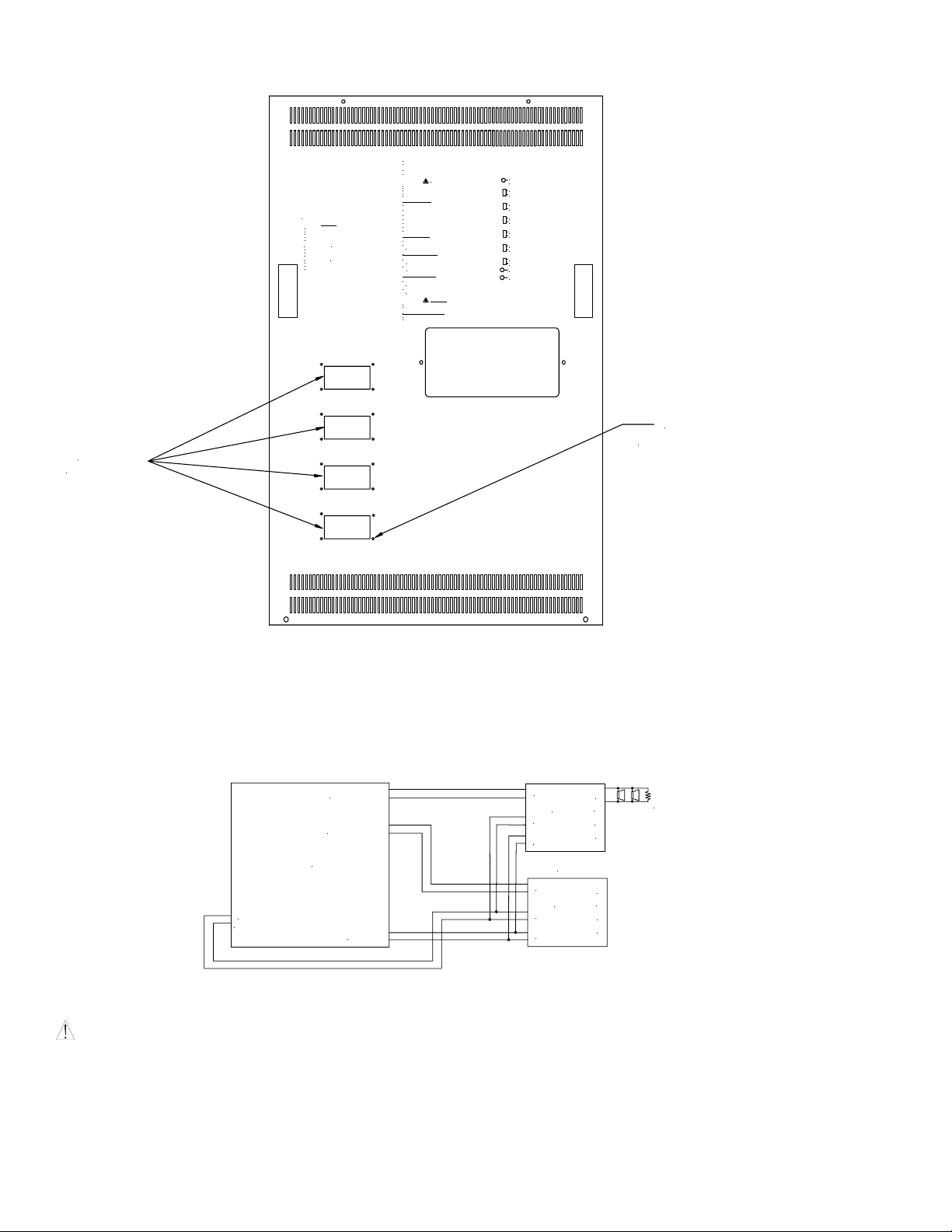
3. Remove the old hole cover on the SAFEPATH Panel’s Dead Front Panel that corresponds to the location of the new splitter
module by removing the 4 hole plugs on the cover. Save the 4 plugs to attach the new cover. (See Figure 3)
4. Attach the Four Zone Splitter cover to the Dead Front Panel using the 4 hole plugs.
Copyright 2003, 2004 Wheelock, Inc. All rights reserved.
P83541 G
Sheet 1 of 6
Page 2

4 MOUNTING HOLE
S
FOR SPLITTER
POWER SUPPLY
PCB COVER
Figure 1:
4 ZONE SPLITTER (1)
PCB STANDOFFS (4)
POWER SUPPLY PCB COVER (1)
Figure 2:
P83541 F
Sheet 2 of 6
Page 3
)
COVER
LOCATIONS
BEFORE REMOVING THIS PANEL:
CAUTION
DO NOT ATTEMPT TO REMOVE OR REPLACE
MODULAR PC BOARDS INSIDE WITHOUT
DISCONNECTING ALL POWER SOURCES TO
THIS UNIT FIRST. FAILURE TO DO SO MAY
RESULT IN DAMAGE TO THE PC BOARDS.
DISCONNECTING
- FIRST DISCONNECT
BATTERY POWER AT THE BATTERY TERMINALS,
THEN DISCONNECT AC POWER AT THE
POWER SOURCE.
RECONNECTING
- FIRST RECONNECT AC
POWER AT THE POWER SOURCE, THEN
RECONNECT BATTERY POWER AT THE BATTERY
TERMINALS.
When the GREEN "NORMAL" LED is ON, the system
is functioning properly.
When the YELLOW "TROUBLE" LED is ON there is a
FAULT in the system which MUST BE CORRECTED.
WARNING
IF THE YELLOW "TROUBLE" LIGHT IS ON, THIS UNIT MAY NOT BE ABLE TO
PROVIDE EMERGENCY ANNOUNCEMENT CAPABILITIES AND COULD RESULT
IN PROPERTY DAMAGE, SERIOUS INJURY OR DEATH TO YOU AND/OR
OTHERS. IN THE EVENT THE "TROUBLE" LIGHT IS ON, YOU SHOULD
CONTACT YOUR SERVICE REPRESENTATIVE IMMEDIATELY.
ACKNOWLEDGEMENT
To Acknowledge a Trouble Condition:
1. Momentarily depress the TROUBLE ACKNOWLEDGE button.
This will only silence the internal sounder and any external
trouble signaling devices. The system will remain in the
trouble condition with the yellow "TROUBLE" LED on and
the system trouble contact will remain in the trouble
position until all trouble conditions have been corrected.
MANUAL OPERATION
To Sound Evacuation Tone:
1. Slide the AUTOMATIC/MANUAL switch DOWN to the
MANUAL position.
MICROPHONE OPERATION
1. Hold the microphone within 2 inches of mouth and
press the push-to-talk switch on microphone.
2. Deliver message. Activation of the microphone will
deliver the message to all circuits.
ZONE DISARRANGEMENT
1. Slide the zone disarrangement switch down to the
DISARRANGEMENT position.
2. To override zone disarrangement, slide the
ZONE SELECT/ALL-CALL switch to ALL-CALL
WARNING
ANY ZONE DISARRANGEMENT WILL SILENCE IT'S RESPECTIVE Z ONE.
IT WILL ALSO PUT THE UNIT INTO A TROUBLE CONDITION.
FOR ADDITIONAL INFORMATION:
FOR SAPE, REFER TO O&M-3/105411
FOR RSAPE, REFER TO O&M-5/107384
TROUBLE
ACKNOWLEDGE
AUTOMATIC
MANUAL
ZONE SELECT
ALL-CALL
ZONE 1
DISARRANGEMENT
ZONE 2
DISARRANGEMENT
ZONE 3
DISARRANGEMENT
ZONE 4
DISARRANGEMENT
NORMAL
TROUBLE
PLUG LOCATIONS
(TYPICAL 4 PER COVER
Figure 3:
WIRING DIAGRAM:
1. See Figure 4 for wiring diagram.
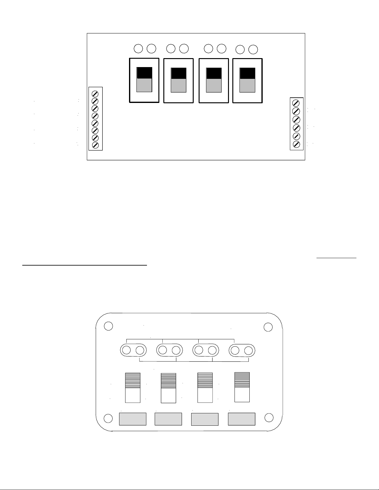
2. See Figure 5 for terminal block wiring designations.
SUPERVISED CIRCUIT
UL LISTED 10K OHM 1W
EOLR RESISTOR
MOTHER BOARD
24V
COM
(SAMB)
ZONE 1 AUDIO
ZONE 2 AUDIO
ALL CALL
AUDIO IN
PWR IN
ALL CALL IN
SPL
Z1
Z2
Z3
Z4
SPL
AUDIO IN
PWR IN
ALL CALL IN
SPL
Z1
Z2
Z3
Z4
Figure 4:
CAUTION: "POWER IN" terminals should be connected to the system power on the left side of the motherboard. Do no connect
to Remote Mic Power above "ALL CALL" terminals.
P83541 F
Sheet 3 of 6
Page 4
_
+
_
+
_
+
_
+
Figure 5:
+
ALL CALL
_
+
POWER IN
_
+
AUDIO IN
_
ZONE 1 OUT
ZONE 2 OUT
ZONE 3 OUT
ZONE 4 OUT
WIRING SPECIFICATIONS:
Cable Size: 14-22 AWG
OPERATING INSTRUCTIONS:
When making a live emergency announcement from the SAFEPATH panel, use the Four Zone Splitter’s four zone ON/OFF switches
to select the zones to which the audio will be broadcast or use the panel’s ALL CALL switch to select all of the zones. To select a
zone, slide the zone ON/OFF switch up to the on position (Figure 6). The ZONE SELECT LED associated with the zone switch will
be lit if the zone is selected. The ZONE ALARM LED’s indicate to which zones audio is currently being broadcast. The splitter will
allow zone selection of live announcements only. Automatic or manual alarm operation will be through all zones.
The splitter detects audio wiring faults (opens and shorts) in the non-alarm mode only. During alarm paging the splitter allows the
selection of any or all zone outputs. The ALL CALL switch overrides all zone selections. To initiate ALL CALL, slide the ALL
CALL switch up to the on position. If there is a trouble in the output wiring or a trouble in the four zone splitter circuit, the trouble
condition will be reported to the respective amplifier card as a speaker wiring trouble and the SPK LED will be lit.
ON
OFF
ZONE 1
4-ZONE SPLITTER
ZONE SELECT LED'S
ZONE ALARM LED'S
ON
OFF
ZONE 2
ON
OFF
ZONE 3
Figure 6:
SPL
ON
OFF
ZONE 4
P83541 F
Sheet 4 of 6
Page 5

TROUBLE SHOOTING PROCEDURES:
1. Be sure the unit is in the standby (non-alarm) mode.
2. Verify all wiring is correct.
3. To verify the system trouble is caused by the splitter or output audio wiring:
Measure the DC voltage at audio ±. If it is -12VDC ±1V, the trouble is caused by something else in the system. (See
appropriate SAFEPATH instruction manual for additional troubleshooting procedures.) If it is -4VDC ±1V, the trouble is
caused by the audio output wiring from the splitter.
4. Measure the DC voltage at the zone outputs ± of the four zones of the splitter. If it is -12VDC ±1V, the zone does not have a
wiring fault. If it is -24VDC ±1V, the trouble is an open in the audio wiring or a missing end-of-line resistor. If it is 0VDC, the
trouble is a short in the audio wiring.
MEA INFORMATION:
Recommendations - That the above units be accepted on condition that all uses, configurations, arrangements and functions, locations
and installations comply with the New York City Building Code, specifically Subchapter 17 and with the Referenced Standard RS 173 through 17-3C including the NFPA as appropriate, the UL Listing, the manufacturer’s instructions, the Fire Department Rules and
the Electrical Code of the City of New York, and on further condition that:
(a) The use, installation and application of the SAFEPATH System shall be restricted exclusively to connection with a BSA/MEA
approved compatible Class E, Class J or Class C Fire Command Station.
(b) The Fire Command Station shall have the capability of overriding any function of the SAFEPATH system.
(c) Prior to the installation of any SAFEPATH System, a specific approval for a specific installation must be obtained from the Fire
Department.
(d) A priority voice message matrix must be submitted to the Fire Department for approval before the installation is performed and
shall include the following information:
1. The duration of each message.
2. The content of each message.
3. The duration of the audible and visual alarm signals prior to the initiation of the subsequent prerecorded message
transmission.
4. The interval between the cessation of the audible and visual alarm signals and the generation of prerecorded message.
(e) The SAFEPATH panel must be located in the room as, and within 20 feet of a BSA/MEA approved Fire Command Station. The
wiring between the SAFEPATH Control Unit and the Fire Command Station must be enclosed in conduit.
(f) Power supply wiring to the SAFEPATH Control Unit shall be installed in the same conduit containing the input and output
wiring.
(g) When used with central office communicator or transmitter, the installation and operation of the equipment and devices listed
herein shall comply with Fire Department Rule #3 - RCNY 17-01, NFPA 71, and shall have the capability of transmitting
separate and distinct signals to indicate manual pull station alarm, automatic smoke/heat detection alarm, sprinkler waterflow
alarm, supervisory signal indications and trouble indications.
(h) The connection of security/burglar devices and equipment to that submitted for acceptance for fire alarm usage under this MEA
application is prohibited within New York City and such equipment and devices shall be so permanently labeled.
All shipments and deliveries of such equipment shall be provided with a metal tag suitably placed, certifying that the equipment
shipped or delivered is equivalent to that tested and accepted for use, as provided for in Section 27-131 of the Building Code.
P83541 F
Sheet 5 of 6
Page 6

Limited Warranty
Wheelock products must be used within their published specifications and must be PROPERLY specified, applied, installed, operated,
maintained and operationally tested in accordance with these instructions at the time of installation and at least twice a year or more
often and in accordance with local, state and federal codes, regulations and laws. Specification, application, installation, operation,
maintenance and testing must be performed by qualified personnel for proper operation in accordance with all of the latest National
Fire Protection Association (NFPA), Underwriters' Laboratories (UL), Underwriters’ Laboratories of Canada (ULC), National
Electrical Code (NEC), Occupational Safety and Health Administration (OSHA), local, state, county, province, district, federal and
other applicable building and fire standards, guidelines, regulations, laws and codes including, but not limited to, all appendices and
amendments and the requirements of the local authority having jurisdiction (AHJ). Wheelock products when properly specified,
applied, installed, operated, maintained and operationally tested as provided above are warranted against mechanical and electrical
defects for a period of three years from date of manufacture (as determined by date code). Correction of defects by repair or
replacement shall be at Wheelock's sole discretion and shall constitute fulfillment of all obligations under this warranty. THE
FOREGOING LIMITED WARRANTY SHALL IMMEDIATELY TERMINATE IN THE EVENT ANY PART NOT FURNISHED
BY WHEELOCK IS INSTALLED IN THE PRODUCT. THE FOREGOING LIMITED WARRANTY SPECIFICALLY
EXCLUDES ANY SOFTWARE REQUIRED FOR THE OPERATION OF OR INCLUDED IN A PRODUCT. WHEELOCK
MAKES NO REPRESENTATION OR WARRANTY OF ANY OTHER KIND, EXPRESS, IMPLIED OR STATUTORY
WHETHER AS TO MERCHANTABILITY, FITNESS FOR A PARTICULAR PURPOSE OR ANY OTHER MATTER.
USERS ARE SOLELY RESPONSIBLE FOR DETERMINING WHETHER A PRODUCT IS SUITABLE FOR THE USER'S
PURPOSES, OR WHETHER IT WILL ACHIEVE THE USER'S INTENDED RESULTS. THERE IS NO WARRANTY AGAINST
DAMAGE RESULTING FROM MISAPPLICATION, IMPROPER SPECIFICATION, ABUSE, ACCIDENT OR OTHER
OPERATING CONDITIONS BEYOND WHEELOCK'S CONTROL.
SOME WHEELOCK PRODUCTS CONTAIN SOFTWARE. WITH RESPECT TO THOSE PRODUCTS, WHEELOCK DOES
NOT WARRANTY THAT THE OPERATION OF THE SOFTWARE WILL BE UNINTERRUPTED OR ERROR-FREE OR
THAT THE SOFTWARE WILL MEET ANY OTHER STANDARD OF PERFORMANCE, OR THAT THE FUNCTIONS OR
PERFORMANCE OF THE SOFTWARE WILL MEET THE USER'S REQUIREMENTS. WHEELOCK SHALL NOT BE LIABLE
FOR ANY DELAYS, BREAKDOWNS, INTERRUPTIONS, LOSS, DESTRUCTION, ALTERATION, OR OTHER PROBLEMS
IN THE USE OF A PRODUCT ARISING OUT OF OR CAUSED BY THE SOFTWARE.
THE LIABILITY OF WHEELOCK ARISING OUT OF THE SUPPLYING OF A PRODUCT, OR ITS USE, WHETHER ON
WARRANTIES, NEGLIGENCE, OR OTHERWISE, SHALL NOT IN ANY CASE EXCEED THE COST OF CORRECTING
DEFECTS AS STATED IN THE LIMITED WARRANTY AND UPON EXPIRATION OF THE WARRANTY PERIOD ALL
SUCH LIABILITY SHALL TERMINATE. WHEELOCK IS NOT LIABLE FOR LABOR COSTS INCURRED IN REMOVAL,
REINSTALLATION OR REPAIR OF THE PRODUCT BY ANYONE OTHER THAN WHEELOCK OR FOR DAMAGE OF ANY
TYPE WHATSOEVER, INCLUDING BUT NOT LIMITED TO, LOSS OF PROFIT OR INCIDENTAL OR CONSEQUENTIAL
DAMAGES. THE FOREGOING SHALL CONSTITUTE THE SOLE REMEDY OF THE PURCHASER AND THE EXCLUSIVE
LIABILITY OF WHEELOCK.
IN NO CASE WILL WHEELOCK'S LIABILITY EXCEED THE PURCHASE PRICE PAID FOR A PRODUCT.
Limitation of Liability
WHEELOCK'S LIABILITY ON ANY CLAIM OF ANY KIND, INCLUDING NEGLIGENCE AND BREACH OF WARRANTY,
FOR ANY LOSS OR DAMAGE RESULTING FROM, ARISING OUT OF, OR CONNECTED WITH THIS CONTRACT, OR
FROM THE MANUFACTURE, SALE, DELIVERY, RESALE, REPAIR OR USE OF ANY PRODUCT COVERED BY THIS
ORDER SHALL BE LIMITED TO THE PRICE APPLICABLE TO THE PRODUCT OR PART THEREOF WHICH GIVES RISE
TO THE CLAIM. WHEELOCK'S LIABILITY ON ANY CLAIM OF ANY KIND SHALL CEASE IMMEDIATELY UPON THE
INSTALLATION IN THE PRODUCT OF ANY PART NOT FURNISHED BY WHEELOCK. IN NO EVENT SHALL
WHEELOCK BE LIABLE FOR ANY CLAIM OF ANY KIND UNLESS IT IS PROVEN THAT OUR PRODUCT WAS A
DIRECT CAUSE OF SUCH CLAIM. FURTHER, IN NO EVENT, INCLUDING IN THE CASE OF A CLAIM OF
NEGLIGENCE, SHALL WHEELOCK BE LIABLE FOR INCIDENTAL OR CONSEQUENTIAL DAMAGES. SOME STATES
DO NOT ALLOW THE EXCLUSION OR LIMITATION OF INCIDENTAL OR CONSEQUENTIAL DAMAGES, SO THE
PRECEDING LIMITATION MAY NOT APPLY TO ALL PURCHASERS.
1/04
P83541 F
Sheet 6 of 6
 Loading...