


SA-90S-MS-24
wheelock SA-90S-MS-24, SA-70S-SL-24, SA-70S-IS-24, SA-70S-LS-24, SA-70S-LSM-24 INSTALLATION INSTRUCTIONS
...
P82991 D
Sheet 1 of 7
273 Branchport Avenue
Long Branch, N.J. 07740
(800) 631-2148 Thank you for using our products.
www.wheelockinc.com
INSTALLATION INSTRUCTIONS
SUPERVISED SELF-AMPLIFIED STROBE SPEAKERS
Use this product according to this instruction manual. Please keep this instruction manual for future reference.
MODEL NUMBERS:
SA-70S-LS-24 1 Watt Supervised Self-Amplified Strobe Speakers Square Flush Grille with 15cd Strobe
SA-70S-LSM-24 1 Watt Supervised Self-Amplified Strobe Speakers Square Flush Grille with 15cd Strobe*
SA-70S-MS-24 1 Watt Supervised Self-Amplified Strobe Speakers Square Flush Grille with 30cd Strobe
SA-70S-IS-24 1 Watt Supervised Self-Amplified Strobe Speakers Square Flush Grille with 75cd Strobe
SA-70S-SL-24 1 Watt Supervised Self-Amplified Strobe Speakers Square Flush Grille with 15cd Synchronized Strobe*
SA-70S-SLM-24 1 Watt Supervised Self-Amplified Strobe Speakers Square Flush Grille with 15cd Synchronized Strobe
SA-90S-LS-24 1 Watt Supervised Self-Amplified Strobe Speakers Round Flush Grille with 15cd Strobe
SA-90S-MS-24 1 Watt Supervised Self-Amplified Strobe Speakers Round Flush Grille with 30cd Strobe
SA-90S-IS-24 1 Watt Supervised Self-Amplified Strobe Speakers Round Flush Grille with 75cd Strobe
SA-90S-SL-24 1 Watt Supervised Self-Amplified Strobe Speakers Round Flush Grille with 15cd Synchronized Strobe
SA-70 models are available with a red or white grille, SA-90 models are available with a white grille only.
GENERAL:
The Supervised Self-Amplified Strobe Speakers are UL Listed under Standard 1480, Speakers for Fire Protective Signaling Systems,
UL Standard 1711, Amplifiers for Fire Protective Signaling Systems, and UL Standard 1971, (Emergency Devices for the Hearing
Impaired) for Indoor Fire Protection Service. They are Listed for indoor use only
. The LSM and SLM strobes are listed at 15
candela under UL Standard 1971 and meet 75 candela intensity on axis with low current draw. The SA Self-Amplified Strobe
Speakers are a combination of a speaker, a 1 watt amplifier and a strobe. The output level is switch selectable for 3 different sound
levels. The SA strobe speaker units are designed to be used with Wheelock’s SAFEPATH Voice Alarm Panel. SA models using
LS/MS/IS/SL are listed for ceiling or wall mount; LSM/SLM models are listed for wall mount only. All SA Strobe Speakers are
designed to fit into a 4” square deep backbox with an extension ring (See Mounting Options).
The SA Strobe Speakers, using the SL and SLM Series Sync Strobes, are designed to work with Wheelock’s Sync Modules; Sync
Control Module (SCM), Sync Module (SM) and the Dual Sync Module (DSM) to provide synchronized flashes when the sync strobes
are activated. Flash rate for the sync strobes with the Sync Modules is a steady one flash per second across a voltage range of 20-
30VDC.
All Supervised Self-Amplified Strobe Speakers use a Xenon flashtube with solid state circuitry enclosed in a rugged Lexan lens to
provide maximum visibility and reliability. All inputs are polarized for compatibility with standard reverse polarity supervision of
circuit wiring by a Fire Alarm Control Panel (FACP).
All models are UL Listed for indoor use with a temperature range of +32
o
F to +120
o
F (0
o
C to +49
o
C) and maximum humidity of
85% RH.
NOTE
: All
CAUTIONS
and
WARNINGS
are identified by the symbol . All warnings are printed in bold capital letters.
WARNING: PLEASE READ THESE INSTRUCTIONS CAREFULLY BEFORE USING THIS PRODUCT. THE SUPERVISED
SELF-AMPLIFIED STROBE SPEAKERS MUST BE FIELD SET TO THE DESIRED SOUND OUTPUT LEVEL BEFORE THEY ARE
INSTALLED. THIS IS DONE BY PROPERLY ADJUSTING A FOUR POSITION SWITCH IN ACCORDANCE WITH THESE
INSTRUCTIONS. INCORRECT SETTINGS WILL RESULT IN IMPROPER PERFORMANCE AND MAY DAMAGE THE PRODUCT,
WHICH COULD RESULT IN PROPERTY DAMAGE AND SERIOUS INJURY OR DEATH TO YOU AND/OR OTHERS.
WARNING: THESE APPLIANCES WERE TESTED TO THE OPERATING VOLTAGE LIMITS OF 20-31 VOLTS USING
FILTERED (DC) OR UNFILTERED FULL-WAVE RECTIFIED (FWR). DO NOT APPLY 80% AND 110% OF THESE VOLTAGE
VALUES FOR SYSTEM OPERATION.
Copyright 1995, 1996, 2000 Wheelock, Inc. All rights reserved.
P82991 D
Sheet 2 of 7
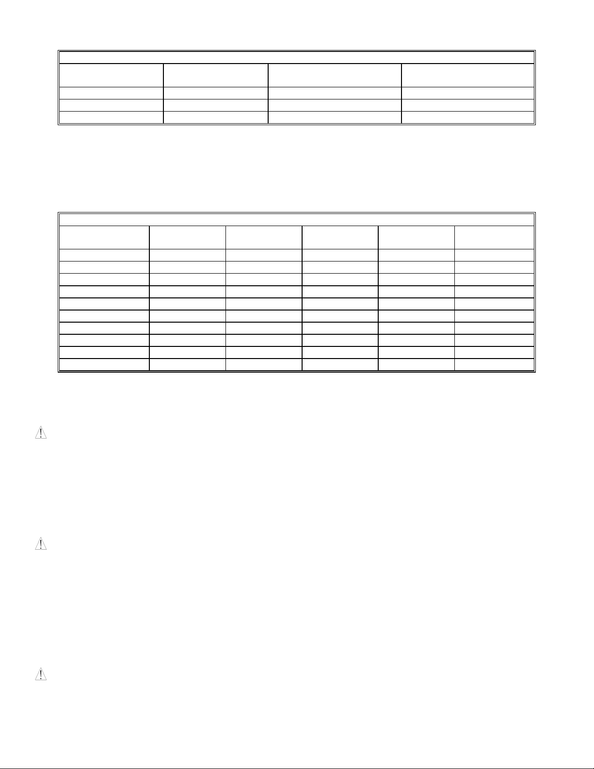
SPECIFICATIONS:
Table 1.
Sound Input Current Typical Anechoic dBA Rated Reverberant dBA
Level mA at 10 Feet Nominal Voltage at 10 Feet Per UL 1480
1 100 91 81
2 83 88 78
3 67 85 75
Power Input Voltage: 20-31VDC
Appliance Input Level: 500mV RMS
Appliance Input Impedance: 600 Ohms
Sound pressure level and current measurements were made with 500mV sinewave appliance.
Anechoic dBA is measured on axis in a non-reflective (free field) test room using fast meter response. Reverberant dBA is a
minimum UL rating based on sound measurements in a reverberant test room.
Table 2: Strobe Specifications
Model Input Strobe Rated Average Rated Peak Rated Inrush
Number Voltage Candela Current Current Current
SA-70S-LS-24 24 15 0.080 0.160 0.210
SA-70S-LSM-24 24 15* 0.115 0.250 0.225
SA-70S-MS-24 24 30 0.135 0.288 0.280
SA-70S-IS-24 24 75 0.240 0.500 0.650
SA-70S-SL-24 24 15 0.096 0.228 0.300
SA-70S-SLM-24 24 15* 0.138 0.320 0.300
SA-90S-LS-24 24 15 0.080 0.160 0.210
SA-90S-MS-24 24 30 0.135 0.288 0.280
SA-90S-IS-24 24 75 0.240 0.500 0.650
SA-90S-SL-24 24 15 0.096 0.228 0.300
(Current is in AMPS)
*15cd models are Listed at 15cd and meet 75cd on axis.
NOTE: THE MAXIMUM WIRE IMPEDANCE BETWEEN STROBES SHALL NOT EXCEED 35 OHMS. THE MAXIMUM NUMBER
OF STROBES ON A SINGLE NOTIFICATION APPLIANCE CIRCUIT SHALL NOT EXCEED 31.
WARNING: MAKE SURE THAT THE TOTAL CURRENT REQUIRED BY ALL APPLIANCES THAT ARE CONNECTED TO
THE SYSTEM'S PRIMARY AND SECONDARY POWER SOURCES AND SIGNALING CIRCUITS, SM AND DSM SYNC MODULES
DOES NOT EXCEED THEIR RATED CURRENT. OVERLOADING THESE SOURCES COULD RESULT IN LOSS OF POWER AND
FAILURE TO ALERT OCCUPANTS DURING AN EMERGENCY, WHICH COULD RESULT IN PROPERTY DAMAGE AND
SERIOUS INJURY OR DEATH TO YOU AND/OR OTHERS.
When calculating the total current: use Table 2 to determine the highest value of "Rated Average Current" for an individual strobe
(across the expected operating voltage range of the strobe); then multiply this value by the total number of strobes; be sure to add the
current for any other appliances, including audible signaling appliances, powered by the same source and include any required safety
factors. Use Table 1 to calculate the total audible appliance current in the same manner.
WARNING: MAKE SURE THAT ALL FUSES USED ON SIGNALING CIRCUITS ARE RATED TO HANDLE THE MAXIMUM
INRUSH OR PEAK CURRENT FROM ALL APPLIANCES ON THOSE CIRCUITS. FAILURE TO DO THIS MAY RESULT IN LOSS
OF POWER TO THE SIGNALING CIRCUIT AND THE FAILURE OF ALL APPLIANCES ON THAT CIRCUIT TO OPERATE,
WHICH COULD RESULT IN PROPERTY DAMAGE AND SERIOUS INJURY OR DEATH TO YOU AND/OR OTHERS.
When calculating the maximum inrush or peak current: use Table 2 to determine the highest value of "Rated Inrush Current" or
"Rated Peak Current" (whichever is higher) for an individual strobe (across the expected operating voltage range of the strobe); then
multiply that value by the total number of strobes on the circuit; be sure to add the inrush or peak currents from any other appliances
on that circuit and include any required safety factors. The time duration of the maximum strobe inrush or peak current is 2
milliseconds for LS/LSM/MS/SL/SLM models and 4 milliseconds for IS models. Calculate the maximum inrush current for all
audible appliances in the same manner. The audible appliances produce a brief inrush current that lasts for just 2 microseconds but
can reach a peak value of 8.0 Amps.
CAUTION
: Strobes are not designed to be used on coded systems in which the applied voltage is cycled on and off.
P82991 D
Sheet 3 of 7
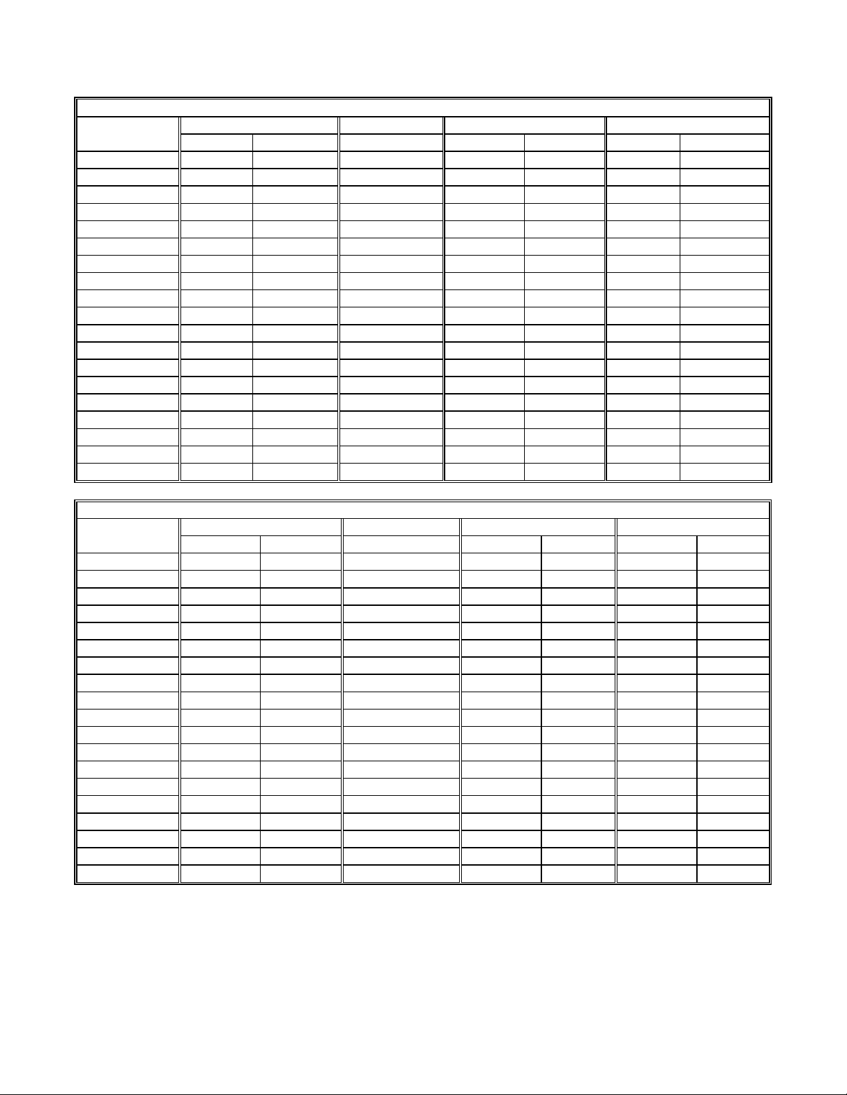
LIGHT DISTRIBUTION:
Table 3: Horizontal Plane
15cd 1575cd * 30cd 75cd Horizontal
Angle (in deg.)
UL Min. Typ. LS/SL Typ. LSM/SLM UL Min. Typ. MS UL Min. Typ. IS
0 15.0 21 100 30.0 42 75.0 90
5 13.5 20 75 27.0 40 67.5 92
10 13.5 20 38 27.0 40 67.5 89
15 13.5 20 28 27.0 40 67.5 86
20 13.5 20 22 27.0 40 67.5 86
25 13.5 20 19 27.0 40 67.5 83
30 11.3 19 19 22.5 38 56.3 77
35 11.3 17 17 22.5 34 56.3 70
40 11.3 17 17 22.5 34 56.3 65
45 11.3 15 16 22.5 30 56.3 62
50 8.3 10 15 16.5 20 41.3 42
55 6.8 8 15 13.5 16 33.8 35
60 6.0 8 15 12.0 16 30.0 33
65 5.3 8 15 10.5 16 26.3 31
70 5.3 8 15 10.5 16 26.3 31
75 4.5 8 15 9.0 16 22.5 31
80 4.5 7 15 9.0 14 22.5 30
85 3.8 7 15 7.5 14 18.8 27
90 3.8 6 14 7.5 13 18.8 26
Table 4: Vertical Plane
15cd 1575cd * 30cd 75cd Vertical
Angle (in deg.)
UL Min.** Typ. LS/SL Typ. LSM/SLM UL Min.** Typ. MS UL Min.** Typ. IS
0 15.0 21 100 30.0 42 75.0 90
5 13.5 21 100 27.0 42 67.5 88
10 13.5 21 100 27.0 42 67.5 87
15 13.5 20 100 27.0 40 67.5 83
20 13.5 19 100 27.0 38 67.5 79
25 13.5 19 98 27.0 38 67.5 74
30 13.5/11.3 18 96 27.0/22.5 36 67.5/56.3 70
35 9.8/11.3 18 94 19.5/22.5 36 48.8/56.3 68
40 6.9/11.3 16 92 13.8/22.5 32 34.3/56.3 66
45 5.1/11.3 14 90 10.2/22.5 28 25.5/56.3 63
50 4.0/8.3 12 84 8.1/16.5 24 20.0/41.3 59
55 3.3/6.8 12 77 6.6/13.5 24 16.3/33.8 54
60 2.7/6.0 9 70 5.4/12.0 18 13.5/30.0 52
65 2.4/5.3 8 63 4.8/10.5 16 12.0/26.3 40
70 2.3/5.3 8 56 4.5/10.5 16 11.3/26.3 31
75 2.0/4.5 8 50 4.0/9.0 16 10.0/22.5 29
80 1.8/4.5 8 30 3.6/9.0 16 9.0/22.5 29
85 1.8/3.8 8 20 3.6/7.5 16 9.0/18.8 28
90 1.8/3.8 8 8 3.6/7.5 16 9.0/18.8 24
* 15cd models are Listed at 15cd and meet 75cd on axis.
** Wall/Ceiling
 Loading...