

Page 1
Helping People Take Action
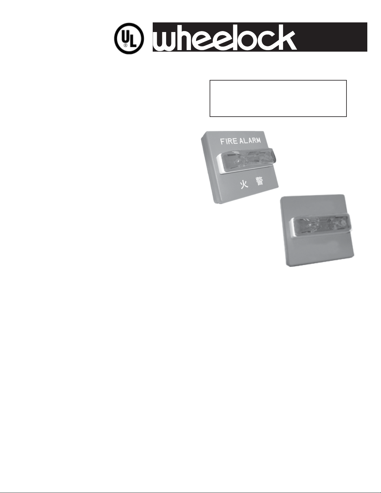
SERIES RSSR STROBES
WITH
RED LENS
SM
Description:
Wheelock’s patented Series RSSR Strobes
with Red Lens have low current draw with
outstanding performance, reliability and costeffectiveness. The Series RSSR S trobes are
UL Listed under S tandard 1638 for Emergency
signaling. All strobes use a Xenon flashtube
enclosed in a rugged Lexan® red lens
dependable visual signaling. Strobes may be
synchronized when used with the Series SM
or DSM Sync Module(s) or Wheelock’s
POWERPATH™ Power Supplies with
Wheelock’s Patented Sync Protocol.
Wheelock’s Series RSSR S trobes employ an
integral, Strobe Mounting Plate that makes it
easy to mount to a variety of backboxes. The
strobes can be mounted to single-gang,
double-gang, 4" square, 100mm European
backboxes or the SHBB surface backbox. An
attractive cover plate is provided for a clean,
finished appearance on all models.
Applications:
Surpression Notification
Process Notification
Emergency Notification
RSSR with
Optional Lettering
RSSR with
No Lettering
Features:
• Appprovals Include: UL 1638 (Indoor)
• Low current draw
• Available with 75 or 1 10cd wall or ceiling
mount
• 24 VDC with 16-33 volt operating range
• Synchronize with Wheelock SM, DSM Sync
Modules or Wheelock’s
POWERP A TH™ Power Supplies
• Patented Strobe Mounting Plate for single
gang, double gang, 4" square 100mm
European backboxes
• Available in Red or White
• Can be Special Ordered with virtually any
lettering (call Customer Service)
Copyright 2004 Wheelock, Inc. All rights reserved.
Page 2
NOTE: All CAUTIONS and WARNINGS are identified by the symbol . All warnings are printed in bold capital letters.
WARNING: PLEASE READ THESE SPECIFICATIONS AND ASSOCIATED INSTALLATION INSTRUCTIONS CAREFULLY BEFORE USING, SPECIFYING OR
APPLYING THIS PRODUCT. FAILURE TO COMPLY WITH ANY OF THESE INSTRUCTIONS, CAUTIONS OR WARNINGS COULD RESULT IN IMPROPER
APPLICATION, INSTALLATION AND/OR OPERATION OF THESE PRODUCTS IN AN EMERGENCY SITUATION, WHICH COULD RESULT IN PROPERTY
DAMAGE, AND SERIOUS INJURY OR DEATH TO YOU AND/OR OTHERS.
General Notes:
• Strobes are designed to flash at 1 flash per second minimum over the Regulated Voltage Range of 16.0 - 33.0 VDC. Note that NFPA-72
(1999) specifies a flash rate of 1 to 2 flashes per second and ADA Guidelines specify a flash rate of 1 to 3 flashes per second.
• All candela ratings represent minimum effective Strobe intensity.
• Series RSSR Strobe products are listed under UL 1638 (for Emergency Signaling) for indoor use with a temperature range of 32°F to 120°F
(0°C to 49°C) and maximum humidity of 85% RH.
• “Regulated Voltage Range” is the newest terminology used by UL to identify the voltage range. Prior to this change UL used the
terminology “Listed Voltage Range”.
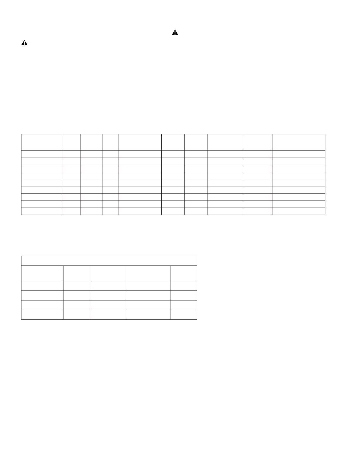
Specifications and Ordering Information
LEDOM
RN-W5742-RSSR1148gniliec/llawdergnirettelon57CDV42002.0513.0X,R,O,N,J,H,G,F,E,D,B
WN-C5742-RSSR2303gniliec/llawetihwgnirettelon57CDV42002.0513.0X,R,O,N,J,H,G,F,E,D,B
WN-C01142-RSSR1113gniliec/lla
RAA-W5742-RSSR0818llawdergnirettelMRALAERIF57CDV42002.0513.0X
WAA-W5742-RSSR6918llawetihwgnirettelMRALAERIF57CDV42002.0513.0X,R,O,N,J,H,G,F,E,D,B
WAA-C57
42-RSSR9718gniliecetihwgnirettelMRALAERIF57CDV42002.0513.0X,R,O,N,J,H,G,F,E,D,B
RAA-W01142-RSSR4228llawdergnirettel
WAA-W01142-RSSR3939llawetihwgnirettelMRALAERIF011CDV42072.0024.0X,R
WAA-C01142-RSSR5228gniliecetihwgnirettelMRALAERIF011CDV42072.0024.0X,R,O,N,J,H,G,F,E,D,B
REDRO
EDOC
rollaW
etalP
gnilieC
wetihwgnirettelon011CDV42072.0024.0X,R,O,N,J,H,G,F,E,D,B
roloC
gniretteL
MRALAERIF011CDV42072.0024.0X,R,O,N,J,H,G,F,E,D,B
EBORTS
ALEDNAC
TUPNI
EGATLOV
EGAREVADETAR
TNERRUCSMR
CDV42@
R*XAMLU
SM
TNERRUC
SNOITPOGNITNUOM
,R,O,N,J,H,G,F,E,D,B
,O,N,J,H,G,F,E,D,B
* RMS current ratings are per UL average RMS method. UL max current rating is the maximum RMS current within the listed
voltage range (16-33v for 24v units). For strobes the UL max current is usually at the minimum listed voltage (16v for 24v units). For
audibles the max current is usually at the maximum listed voltage (33v for 24v units). For unfiltered FWR ratings, see installation
instructions.
YLPPUSREWOP/SELUDOMCNYS
rebmuNledoM
#
R-42/21-MS
##
R-42/21-MSD
###
PM8-42/21-SP
###
PC8-42/21-SP
redrO
edoC
963642520.W
473642830.W
6403CAV032/021-7403CAV032/021--
# SM Sync Module is rated for 3.0 amperes @ 24 VDC;
## DSM Sync Module is rated for 3.0 amperes per circuit. The
maximum number of interconnected DSM Modules is twenty (20).
Refer to Data Sheet S3000 or Installation Instructions (P83123 for
SM and P83177 for DSM).
### Refer to Data Sheet S9000 or Installation
Instructions P84515 for PS-12/24-8CP or P84333 for PS-12/24-8MP
Power Supplies.
**Refer to Data Sheet S7000 for Mounting Options.
egatloVtupnI
)CDV(
*tnerruCegarevA
CDV42@)SPMA(
gnitnuoM
**snoi
tpO
Page 3

WARNING: CONTACT WHEELOCK FOR THE CURRENT “INSTALLATION INSTRUCTIONS” SERIES RSSR (P83884)
“GENERAL INFORMATION” SHEET (P82380) ON THESE PRODUCTS. THESE DOCUMENTS UNDERGO PERIODIC
CHANGES. IT IS IMPORTANT THAT YOU HAVE CURRENT INFORMATION ON THESE
PRODUCTS. THESE MATERIALS CONTAIN IMPORTANT INFORMATION THAT SHOULD BE READ PRIOR TO SPECIFYING
OR INSTALLING THESE PRODUCTS, INCLUDING:
• TOTAL CURRENT REQUIRED BY ALL APPLIANCES CONNECTED TO SYSTEM SECONDARY POWER SOURCES.
• FUSE RATINGS ON NOTIFICATION APPLIANCE CIRCUITS TO HANDLE PEAK CURRENTS FROM ALL APPLIANCES ON THOSE
CIRCUITS.
• COMPOSITE FLASH RATE FROM MULTIPLE STROBES WITHIN A PERSON’S FIELD OF VIEW.
• ADDING, REPLACING OR CHANGING APPLIANCES COULD EFFECT CURRENT DRAW.
RECALCULATE CURRENT DRAW TO INSURE THAT THE TOTAL AVERAGE CURRENT AND TOTAL PEAK REQUIRED BY ALL
APPLIANCES DO NOT EXCEED THE RATED CAPACITY OF THE POWER SOURCES OR FUSES.
• THE VOLTAGE APPLIED TO THESE PRODUCTS MUST BE WITHIN THEIR “REGULATED VOLTAGE RANGE”.
• USE STROBES ONLY ON CIRCUITS WITH CONTINUOUSLY APPLIED OPERATING VOLTAGE. DO NOT USE STROBES ON CODED
OR INTERRUPTED CIRCUITS IN WHICH THE APPLIED VOLTAGE IS CYCLED ON AND OFF AS THE STROBES MAY NOT FLASH.
• FAILURE TO COMPLY WITH THE INSTALLATION INSTRUCTIONS OR GENERAL INFORMATION SHEETS COULD RESULT IN
IMPROPER INSTALLATION, APPLICATION, AND/OR OPERATION OF THESE PRODUCTS IN AN EMERGENCY SITUATION, WHICH
COULD RESULT IN PROPERTY DAMAGE AND SERIOUS INJURY OR DEATH TO YOU AND/OR OTHERS.
• CONDUCTOR SIZE (AWG), LENGTH AND AMPACITY SHOULD BE TAKEN INTO CONSIDERATION PRIOR TO DESIGN AND
INSTALLATION OF THESE PRODUCTS, PARTICULARLY IN RETROFIT INSTALLATIONS.
Wiring Diagrams
#
SERIES RSSR APPLIANCE
FROM
PRECEDING
APPLIANCE, SYNC
MODULE, POWER
SUPPLY OR FACP
+
-
-
+
TO NEXT
+
APPLIANCE
OR EOLR
SERIES RSSR APPLIANCES SYNCHRONIZED WITH DSM
MODULE SINGLE CLASS “A” NAC CIRCUIT
DSM
SYNC
+OUT 1
+ IN 1
MINUS 1
+
MINUS 2
+ IN 2
+ OUT 2
+
-
AUDIBLE
-
RSSR
RSSR
RSSR RSSR
RSSR RSSR
FACP
STROBE
NAC
CIRCUIT
OUT
STROBE
NAC
CIRCUIT
RETURN
SERIES RSSR APPLIANCES SYNCHRONIZED
WITH PS-12/24-8CP or PS-12/24-8MP
Series PS-12/24-8
SERIES RSSR APPLIANCE SYNCHRONIZED WITH SM
MODULE SINGLE CLASS “B” NAC CIRCUIT
SM
+
F
Strobe
A
NAC
Circuit
C
P
SERIES RSSR APPLIANCES SYNCHRONIZED WITH
MUL TIPLE DSM MODULES
Strobe NAC Cir .
F
A
Strobe NAC Ci r .
C
P
Strobe NAC Cir .
DSM Interconnecting wiring shown. Maximum of
STROBE
-
STROBE
+
Audible
EOLR
-
Audible
DSM #1
Sync
+
-
DSM #2
Sync
+
-
DSM #3
Sync
+
-
twenty (20)
RSSR
RSSR RSSR
RSSR RSSR
RSSR RSSR
RSSR
OUTPUTS
F
A
C
1-4
4-CLASS
"B"
OR
2-CLASS
"A"
AS
AS
RSSR
RSSR
EOLR
P
Series PS-12/24-8CP
or PS-12/24-8MP
AS
# For detail using SM or DSM Sync Module refer to Data Sheet S3000 or Installation Instructions (P83123 for SM and P83177 for DSM).
For wiring information on the PS-12/24-8CP and PS-12/24-8MP Power Supplies refer to Installation Instructions P84515 and P84333.
Wheelock products must be used within their published specifications and must be PROPERLY specified, applied, installed, operated, maintained and
operationally tested in accordance with their installation instructions at the time of installation and at least twice a year or more often and in accordance with
local, state and federal codes, regulations and laws. Specification, application, installation, operation, maintenance and testing must be performed by
qualified personnel for proper operation in accordance with all of the latest National Fire Protection Association (NFPA), Underwriters’ Laboratories (UL),
National Electrical Code (NEC), Occupational Safety and Health Administration (OSHA), local, state, county, province, district, federal and other applicable
building and fire standards, guidelines, regulations, laws and codes including, but not limited to, all appendices and amendments and the requirements of the
local authority having jurisdiction (AHJ).
RSSR
Page 4

Architects and Engineers Specifications
The visual notification appliances shall be Wheelock Series RSSR Strobe Appliances with Red Lens, or approved
equals. The strobes shall be UL 1638 approved for indoor use only . All strobes shall be certified to meet FCC Part
15 Class B. The strobe appliances shall produce a flash rate of one (1) per second minimum over the Regulated
Volt age range of 16 to 33 VDC for 24-volt models. All inputs shall be polarized for compatibility with standard
reverse polarity supervision of circuit wiring by a Fire Alarm Control Panel (F ACP).
All visual appliances shall incorporate a Xenon flashtube enclosed in a rugged Lexan® red lens. The Series
RSSR Strobes with Red Lens shall be of a low current design. Series RSSR S trobe Appliances with Red Lens
shall incorporate circuitry for synchronized strobe flash and shall be designed for compatibility with Wheelock’s
Series SM, DSM Sync Module(s) or Wheelock’s PS-12/24-8MP and PS-12/24-8CP Power Supplies with Wheelock’s
Patented Sync Protocol. The strobes shall not drift out of synchronization at any time during operation. If the
sync module fails to operate (i.e., contacts remain closed), the strobes shall revert to a non-synchronized flash
rate.
The visual appliance shall be designed for indoor surface or flush mounting. Series RSSR with Red Lens models
shall employ a patented S trobe Mounting Plate that shall allow mounting to a single-gang,
double-gang, 4 inch square, 100mm European type backboxes, or the SHBB Surface Backbox. If required, an
NA TP (Notification Appliance Trim Plate) shall be provided. An attaching cover plate shall be provided to give the
appliance an attractive appearance. The aesthetic appearance shall not have any mounting holes or screw heads
visible when the installation is completed.
Due to continuous development of our products, specifications and offering are subject to change without notice i accordance
with Wheelock, Inc. standard terms and conditions.
WE ENCOURAGE AND SUPPORT NICET CERTIFICATION
MADE IN THE USA
3 YEAR WARRANTY
Distributed By:
NATIONAL SALES OFFICE
800-631-2148
Canada 800-397-5777
E-Mail: Info@wheelockinc.com
http://www.wheelockinc.com
273 BRANCHPORT AVENUE • LONG BRANCH, NJ 07740 • TEL: 732-222-6880 • FAX: 732-222-2588
www.wheelockinc.com * E-mail: info@wheelockinc.com
S9008 09/04
 Loading...