

Page 1
THE CITY OF
NEW YORK
DEPARTMENT OF BUILDINGS
ACTION MESSAGE S
ADA
SYSTEMS
U
L
COMMUNICATIONS
®
INC.
Helping People Take Action
SM
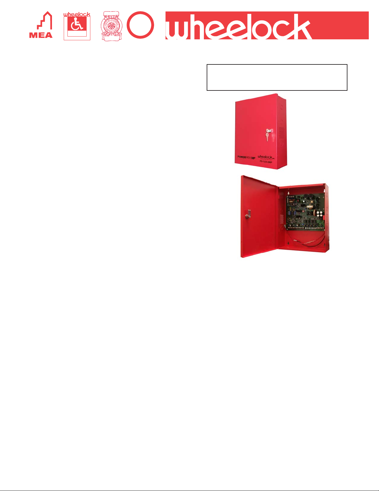
Description
POWERPATH™ Series PS-12/24-8CP and PS-12/24-8MP are
power limited 8 amp power supply/chargers used to expand
the supervised power capability of a fire alarm control panel
(FACP) for notification appliance circuits (NAC).
The PS-12/24-8CP provides up to 200 milliamps of continuous
auxiliary output that can be used for control functions during
alarm (or up to 60 milliamps for 60 hour battery requirements).
The PS-12/24-8MP provides up to 3.5 amps of auxiliary output
that is available only during nonalarm condition for such
applications as door holder systems.
Both models provide regulated and filtered 12 or 24 VDC output
to four (4) Class “B” or two (2) Class “A” circuits. Each Class “B”
circuit has a rating of three (3) amps with a total output of up to
eight (8) amps. Each Class “A” circuit is rated at three (3) amps.
Two (2) Class “A” or Class “B” inputs from an FACP and two (2)
dry contact inputs are provided to trigger the outputs. The units
accept either 12 or 24 VDC inputs and provide 12 or 24 VDC
outputs. Both units support a full 8 amps of notification power
even if the battery is in a degraded mode and only AC power is
connected.
POWERPATH™ Series PS-12/24-8CP and PS-12/24-8MP are
compatible with all Wheelock 12 or 24 VDC Life Safety Notification
Appliances and with their Patented BUILT-IN SYNCHRONIZED
MODE feature, they can control and operate all of Wheelock’s
Synchronized Notification Appliances, including silencing
audibles while maintaining strobe activation.
POWERPATH™
NAC POWER SUPPLIES
Series PS-12/24-8CP
Series PS-12/24-8MP
(Batteries Not Included)
Features
Approvals
• Approvals Include: UL Standard 864, California State Fire
Marshal (CSFM), (New Y ork City (MEA), Factory Mutual
(FM), Chicago (BFP) See Approvals by model in
Specification and Ordering Information
• Compliant with NFPA 72
Inputs
• Compatible with 12 or 24 VDC F ACP
• 115 VAC @ 50/60 Hz or 240 VAC @ 50/60 Hz
• Two 12 or 24VDC NAC Initiating Circuits from host panel
• Two “Dry” contact input circuits
• Accepts 2 Class “A” or 2 Class “B” NAC circuit inputs
• Additional activation options are: NC contacts or open
collector of a transistor
Outputs
• 8 amperes rated supply current @ 12 or 24 VDC
• Filtered and regulated power supply outputs
• Class 2 rated power limited outputs
• Dip switch selectable options
• Field selectable 12 or 24 VDC outputs
• 4 Class “B” or 2 Class “A” or 1 Class “A” and 2 Class
“B” Notification Appliance Circuits)
• Each Class “B” output has a maximum rating of three
(3) amperes
• Each Class “A” output has a maximum rating of
three (3) amperes
• Code 3 (Temporal) option
• Steady output option
Copyright 2004 Wheelock, Inc. All rights reserved.
Outputs Cont.
• Built-In Wheelock Synchronization Protocol
• Input and output synchronization (including pass
through)
Supervision
• FACP NAC supervision steered to either input #1 or #2
• Common input and output trouble circuit
• Input and output LED indicators
• AC fail supervision (Form “C” contacts rated @ 1 amp
@ 24 VDC or 1 15 VAC)
• Battery presence and low battery supervision (Form
“C” contacts rated @ 1 amp @ 24 VDC or 115 VAC)
• Ground fault detection
• 4 latching LED’s for NAC trouble annunciation
Power
• Not Battery Dependent - Full 8A even if battery is
degraded
• Automatic switch over to standby batteries when AC
fails
• Supports sealed lead acid or gel type batteries
• Fused battery protection
• Thermal and short circuit protection with auto reset
• Supports both 7AH or 12AH batteries in the same
cabinet (Cabinet Size: 16" H x 12.25" W x 5" D)
Auxiliary Power
• Up to 200 mA continuous with PS-12/24-8CP
• Up to 3.5 amps nonalarm with PS-12/24-8MP
Page 2
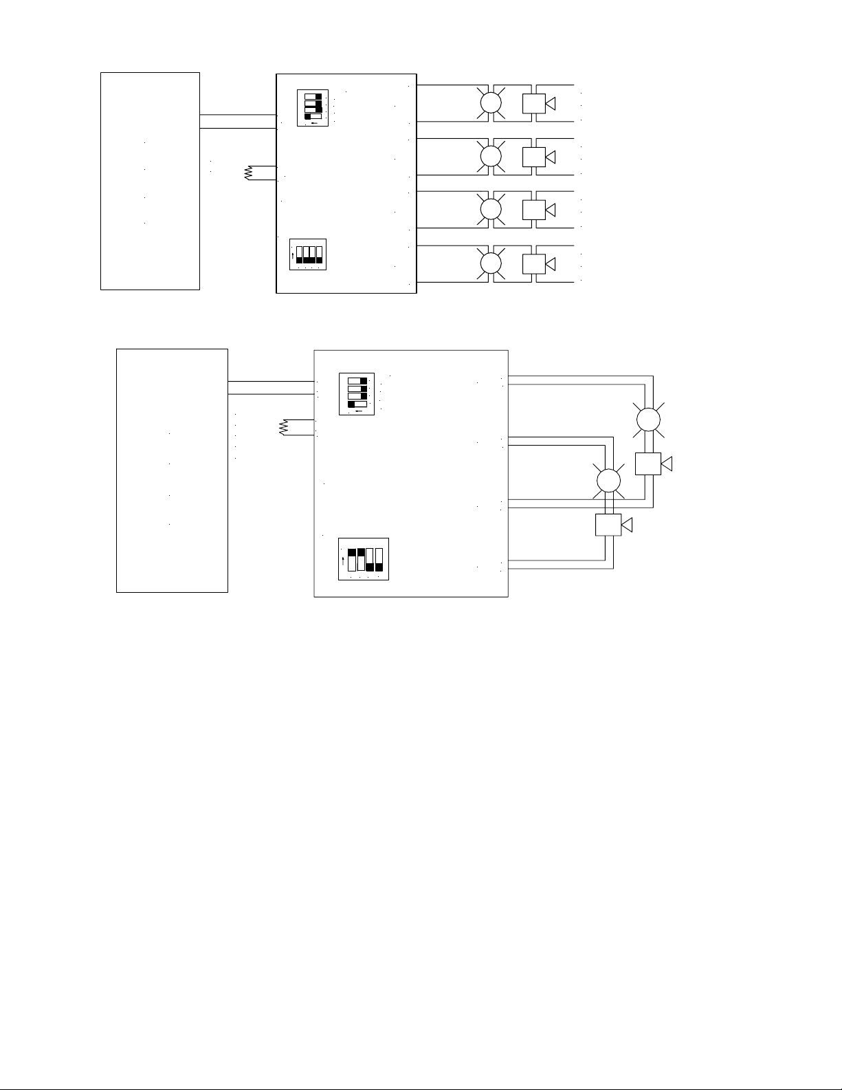
Normal Mode (Class B)
F
A
TO NEXT APPLIANCE
OR EOLR
C
P
Normal Mode (Class A)
TO NEXT APPLIANCE
F
A
OR EOLR
OR RETURN
TO FACP
(CLA S S "A ")
C
P
OUT1-4
4
IN>OUT SYNC
3
WHEELOCK SYNC
2
ON
TEMPOR AL
1
INPUT SELECT
+
-
+
-
IN1
RET1
POW ERPATH
SW9
ON
4
2
3
1
+
IN1
-
ON
+
RET1
-
+
OUT1
-
+
OUT2
-
+
OUT3
-
+
OUT4
-
OUT1-4
4
IN>OUT SYNC
3
WHEELOCK SYNC
2
TEMPORAL
1
INPUT SELECT
POWERPATH
SW9
ON
4
2
3
1
OUT1
OUT2
OUT3
OUT4
TO NEXT APPLIANCE
OR EOLR
(2.2K OH MS)
TO NEXT APPLIANCE
OR EOLR
(2.2K OH MS)
TO NEXT APPLIANCE
OR EOLR
(2.2K OH MS)
TO NEXT APPLIANCE
OR EOLR
(2.2K OH MS)
+
-
+
-
+
+
POWERPATH™ Operating Modes (refer to Installation Manual):
Normal Mode: Provides constant 12 VDC or 24 VDC output upon initiation by a
voltage to input IN1 or IN2 or by a contact opening on DRY1 or DRY2. The unit returns
to standby mode when the input is deactivated.
Wheelock Sync Mode: Provides signals for synchronization of patented Wheelock
audible and strobe notification appliances. Audibles can also be silenced in this mode
while the strobes continue to flash.
In>Out Sync Mode: Accepts a coded signal or synchronization signal on the input to
provide a coded output or synchronized output. This signal may come from a F ACP,
another POWERP A TH or a Wheelock SM or DSM synchronization module. Caution:
Do not use strobes on coded output circuits.
T emporal Mode: Codes the output voltage in a code-3 temporal pattern to drive audible
appliances such as horns, bells or chimes. Caution: Do not use strobes on coded
output circuits.
Page 3

Project
Notification Appliance Circuit
Layout and Design
Subject
No.
By
Date
Page 4

Architects and Engineers Specifications
The power supplies shall be Wheelock POWERPATH™ Series PS-12/24-8CP or PS-12/24-8MP, or equivalent. The units shall
be stand alone power supplies intended for powering fire alarm notification appliances via their own Notification Appliance Circuit(s)
(NAC). The units shall be UL 864 Listed for power limited operation of their outputs and comply with NFPA 70 (NEC), article
760.
The power supplies shall support a full 8A of notification power even if the battery is in a degraded mode and only AC power
is connected.
The power supplies shall be activated by a standard Notification Appliance Circuit (NAC) from any Fire Alarm Control Panel (FACP)
or a “Dry contact” closure. The units shall be 8 ampere, 12 or 24 VDC, regulated and filtered, supervised remote power supply/
chargers. The power supplies shall provide a full 8 amperes of current and shall not be battery dependent. They shall operate
over the voltage range of 8 to 33 VDC or FWR. The primary application of the units shall be to expand fire alarm system
capabilities for additional NAC circuits to support ADA requirements and to provide auxiliary power to support system accessories
or functions. The power supplies shall provide four Class “B”, two Class “A”, or two Class “B” and one Class “A” NAC circuit(s).
The PS-12/24-8CP units shall also supply up to 200 mA of auxiliary power that is available during both nonalarm and alarm.
The PS-12/24-8MP units shall also supply auxiliary power of not less than 3.5A at 24 VDC during nonalarm. The power
supplies shall be capable of charging batteries of up to 12 ampere hours per NFPA 72 (1999). Input activation options shall be
from not less than two NAC circuits or Dry Contact closures. These inputs shall have the capability of being directed to any
combination of the four NAC circuit outputs. Each NAC circuit output shall be rated at 3 amperes for Class “B” applications or
3 amperes each for Class “A”. The outputs shall be programmable to generate a steady or Temporal (Code 3) output and or
a synchronized strobe or horn output. The power supplies shall provide independent loop supervision for either Class “A” or
Class “B” FACP NAC circuits and shall have the capability to “steer” all alarm or trouble conditions to either incoming NAC
circuit. The units shall have common output terminals. The power supplies shall be powered from a 120 VAC or 240 VAC
source with a current consumption of 5 amperes max. The unit shall incorporate short circuit protection with auto reset. The
power supply shall incorporate a built in battery charger for lead acid or gel type batteries with automatic switchover to battery back
up in the event of AC power failure. The charger shall incorporate fused protection for the batteries and have the ability to report
low battery and/or no battery condition(s). Standby current for battery back up shall be 100 mA max. The cabinet dimensions
shall be 16" H x 12.25" W x 5" D.
WARNING: PLEASE READ THESE SPECIFICATIONS AND INSTALLATION INSTRUCTIONS CAREFULLY BEFORE USING, SPECIFYING OR APPLYING
THIS PRODUCT. FAILURE TO COMPLY WITH ANY OF THESE INSTRUCTIONS, CAUTIONS AND WARNINGS COULD RESULT IN IMPROPER APPLICATION,
INSTALLATION AND/OR OPERATION OF THESE PRODUCTS IN AN EMERGENCY SITUATION, WHICH COULD RESULT IN PROPERTY DAMAGE, AND
SERIOUS INJURY OR DEATH TO YOU AND/OR OTHERS.
Specifications and Ordering Information
rebmuNledoMedoCredrOtnerruC/egatloVtupnI
PC8-42/21-SP7403.xamspma0.5;zH06/05@CAV022/021X*X*
PM
8-42/21-SP6403.xamspma0.5;zH06/05@CAV022/021XXXX
stiucriCCANtuptuO tnerruC/egatloVtuptuO
”B“ssalC)4(ruoF tiucri
ro”A“ssalC)2(owT tiucriCrepspma3@CDV42/21
"B"ssalC)2(owTdna"A"ssalC)1(enO
tnerruCybdnatS
tnerruCmralA
t
nerruCCANlatoT
seirettaBybdnatS
HA21/CDV42
HA21/CDV21
)seiresniseirettabCDV21)2(owtsesu(
ybdnatS
emiT
sruoH42setuniM51/spmA8
sruoH06setuniM51/spmA8Am06
sruoH42setuniM51/spmA8Am0
sruoH06setuniM51/spmA8Am06
tuptuOmralA
setuniM/spmAlatoT
Crepspma3@CDV42/21
ucriCrepspma3@CDV42/21
spmA060.0
spmA001.0
.xaMspmA8
tuptuOxuA
gnirudA5.3
mralanon
LUAEMMFSCMF
X= Approved
*= Pending
)"A"ssalC(ti
)"B"ssalC(tiucriCrepspma3@CDV42/21
ptuOxuA
PM8-42/21-SP
Am002
02
slavorppA
tu
PC8-42/21-SP
NOTE: Due to continuous development of our products, specifications and offerings are subject to change without notice
in accordance with Wheelock Inc. standard terms and conditions.
WE ENCOURAGE AND SUPPORT NICET CERTIFICATION
National Sales Office
800-631-2148
Canada 800-397-5777
E-Mail: Info@wheelockinc.com
273 Branchport A venue • Long Branch, NJ 07740 • TEL: 732-222-6880 • FAX: 732-222-2588
3 YEAR WARRANTY
Made in USA
Distributed By:
S9000 11/04
 Loading...