

Page 1
INC.
Helping!People!Take!Action
TM
FIRE ALARM SYSTEMS
SERIES ET SPEAKERS &
Description
Wheelock’s Series ET provides a full range of rugged, high
performance speakers and speaker strobe combinations specifically designed to meet the critical needs of the life safety
industry for voice and tone signaling. A vailable in compact,
aesthetically pleasing package styles, each ET model covers both 25 or 70 volt audio systems. Their high-efficiency
design provides improved evacuation signal, such as the “slow
whoop” and “code-3”. The Series ET provides unequaled performance and installation flexibility at the job site, while minimizing confusion about mounting and performance capabilities.
Series ET S peaker Strobes use an Xenon flashtube with solid
state circuitry enclose din a rugged Lexan® lens to provide
maximum reliability for effective visible signaling.
All Series ET models have IN and OUT wiring terminals that
accept two #12 to #18 American Wire Gauge (A WG) wires at
each terminal. Strobe input s are polarized and audio inputs
include a 10 uF blocking capacitor for compatibility with standard reverse polarity DC supervision of NAC circuits.
Features
• Approvals include: CAN/ULC-S541-99 for speaker appliances
and CAN/ULC-S526-02 for visual appliances
• High efficiency design for maximum output at minimum wattage
across a frequency range of 400 to 4000 HZ
• Field selectable taps for 25 VRMS operation from 1/8 watt to 2
watts
• Field selectable taps for 70 VRMS operation from 1/8 watt to 8
watts.
• Series ET Speaker S trobes models available with 15 candela
strobes featuring low current draw and low temperature compensation to reduce power consumption and wiring costs
• All audio and strobe inputs are compatible with standard
reverse polarity type supervisions of circuit wiring by an alarm
panel
• Four attractive package styles for flush, semi-flush or surface
mounting to low cost electrical backboxes
• Choice of vandal resistant die cast grilles (ET -1010/1080) or
general purpose sheet metal grilles (ET-1070/1090)
• Sealed back speaker construction for extra protection and
improved audibility
• Sealed back speaker construction for extra protections and
improved audibility
• Fast installation with IN/OUT screw terminals using #12 to #18
AWG wires
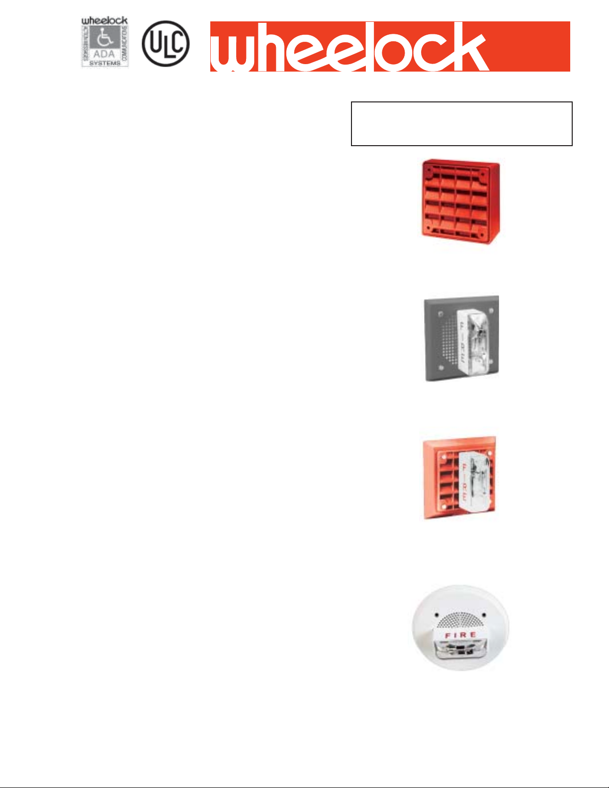
SPEAKER STROBES
Series ET-1010
Vandal Resist ant
Series ET-1070 + LS
Series ET-1080 + LS
V andal Resistant w/Stobe
Series ET-1090 +LS
Copyright 2003 Wheelock Inc. All rights reserved.
39
Page 2
NOTE: All CAUTIONS and WARNINGS are identified by the symbol . All warnings are printed in bold capital letters.
WARNING: PLEASE READ THESE SPECIFICA TIONS AND ASSOCIA TED INST ALLA TION INSTRUCTIONS CAREFULL Y BEFORE USING,
SPECIFYING OR APPL YING THIS PRODUCT. F AILURE TO COMPLY WITH ANY OF THESE INSTRUCTIONS, CAUTIONS OR W ARNINGS
COULD RESULT IN IMPROPER APPLICA TION, INST ALLA TION AND/OR OPERATION OF THESE PRODUCTS IN AN EMERGENCY SITUA TION,
WHICH COULD RESULT IN PROPERTY DAMAGE, AND SERIOUS INJUR Y OR DEA TH TO YOU AND/OR OTHERS.
CAUTION: Always operate audio amplifiers and speakers within their specified ratings. Excessive input may distort sound quality and may
damage audio equipment. Do not exceed +30% of speaker rated voltage per CS 243. Improper input voltage can damage speaker. If distortion
is heard, check for clipping of the audio signal with an oscilloscope and reduce the amplifier level or gain level to eliminate any clipping.
Specifications
**teeF01@BdrekaepS
rebmuNledoM
8/14/12/112*4*8MON
0101-TE87184878093969- 0701-TE87184878093969- 0801-TE87184878093969- 0901-TE87184878093969- -
42-SL-0701-TE871848780939694251
42-SL-0801-TE871848780939694251
42-SL-0901-TE871848780939694251
)sttaWdetaR(
egatloVebortS
)CDV(
ebortS
Notes: 1. Frequency range of speakers is 400-4000
alednaC
Hz. 2. A 10 uF blocking capacitor for DC Supervisoin
of audio lines by the FACP is factory wired in series
with the speaker input. 3. dBA is rated per UL 1480.
*4 and 8 watt taps not available
for 25 VRMS applications.
egarevAdetaR
egatloV
tnerruC
SL
kaePdetaR
tnerruC
SL
SL
CDV42080.091.052.
RWFV42180.612.083.
General Notes:
• Strobes are designed to flash at 1 flash per second minimum over their Regulated Voltage Range.
• ET-1010 Speakers are Listed for indoor/outdoor use with a temperature range of -35°C to 66°C (-31°F to 150°F) and maximum
humidity of 95% RH. All other ET Speakers and Speaker Strobes are Listed for indoor use with a temperature range of 0°C to
49°C (32°F to 120°F) and maximum humidity of 85%RH.
WARNING: USE STROBES ONL Y ON NAC CIRCUITES WITH CONTINUOUSL Y APPLIED OPERA TING VOL TAGE. DO NOT USE STROBES ON
CODED OR INTERRUPTED NAC CIRCUITS IN WHICH THE APPLIED VOL T AGE IS CYCLED ON AND OFF , AS THE STROBE MA Y NOT FLASH.
seireSrebmuNledoM
redrO
edoC
Note: All VFWR voltages in table are measured with DC volt meter.
hsurnIdetaR
Multiply VFWR voltage by 1.11 to convert to VRMS.
tnerruC
WARNING: AL THOUGH UL TESTING HAS VERIFIED THA T THESE
STROBES FUNCTION EVEN A T 80% OF THEIR MINIMUM RA TING AND
110% OF THEIR MAXIMUM RA TING, WHEELOCK STRONGL Y RECOMMENDS THAT THE VOL T AGE APPLIED TO THESE PRODUCTS BE
WITHIN THEIR RATED INPUT VOL T AGE RANGE. THE APPLICA TION OF
IMPROPER VOLT AGE MA Y RESUL T IN DEGRADED OPERA TION OR
DAMAGE TO THESE PRODUCTS.
The UL “Listed Rated Input Voltage” uses either filtered (DC) or unfiltered
full-wave-rectified (FWR) voltage. Check the minimum and maximum
output of the power supply and stand by battery and subtract the voltage
drop from the circuit wiring resistance to determine the applied voltage to
the strobes.
ebortS
alednaC
@ABd
teeF01
egarevAebortS
CDV42@tnerruC
gnitnuoM
snoitpO
CLU-R-0101-TE6604- 69-87- S,R,N,K,E
TE
srekaepS
CLU-R-0701-TE3424- 69-87- V,Q,P,O,L,E
CLU-R-0801-TE7334- 69-87- Q,P,O,L,E
CLU-W-0901-TE1324- 69-87- V,Q,O,N,E
TE
rekaepS
sebortS
Notes: 1. Models code suffix V= vertical lens; C= ceiling lens; F= fire lettering; R= red plate; W= white plate. 2. Approval codes:
ULC= Underwriter Laboratories of Canada.
CLU-RFV-42-SL-0701-TE44165169-87470.V,Q,P,O,L,E
CLU-RFV-42-SL-0801-TE54165169-87470.Q,P,O,L,E
CLU-WFV-42-SL-0901-TE64165169-87470.V,Q,O,N,E
40
Page 3

WARNING: CONT ACT WHEELOCK FOR THE CURRENT “INST ALLATION INSTRUCTIONS” AND “GENERAL INFORMA TION”
SHEET ON THESE PRODUCTS. THESE MA TERIALS CONTAIN IMPORT ANT INFORMA TION THA T SHOULD BE READ PRIOR TO
SPECIFYING THESE PRODUCTS, INCLUDING:
• TOTAL CURRENT REQUIRED BY ALL APPLIANCES CONNECTED T O SYSTEM SECONDARY POWER SOURCES.
• FUSE RATINGS ON NAC CIRCUITS TO HANDLE MAXIMUM INRUSH OR PEAK CURRENTS FROM ALL APPLIANCES ON THOSE NAC
CIRCUITS. THE TIME DURATION OF THE MAXIMUM STROE INRUSH OR PEAK CURRENT IS 2 MILLISECONDS FOR LS MODELS.
• INSTALLATION IN OFFICE AREAS AND OTHER SPECIFICA TION AND INST ALLA TION ISSUES.
Application Notes:
CAUTION: Check that the installed product will have sufficient clearance and wiring room prior to
installing backboxes and conduit, especially if sheathed multiconductor cable or 3/4” conduit
fittings are used.
1. Mounting hardware for each mounting option is supplied.
2. Conduit entrances to the backbox should be selected to provide sufficient wiring clearance for
the installed product. When extension rings are required, conduit should enter through the
backbox, not the extension ring. Note not all Canadian Extension Rings fit Series E. Call factory
for assistance.
3. When terminating field wires, do not use more lead length than required. Excess lead length
could result in insufficient wiring space for the signaling device.
4. Use care and proper techniques to position the field wires in the backbox so that they use
minimum space and produce minimum stress on the product. This is especially important for stiff,
heavy gauge wires and wires with thick insulation or sheathing.
5. Do not pass additional wires (used for other than the signaling device) through the backbox.
Such additional wires could result in insufficient wiring space for the signaling appliance.
Wiring Diagrams
#
SPEAKER AND STROBE OPERA TE INDEPENDENTL Y
FROM
+
PRECEDING
APPLIANCE
OR VOICE
EVACUATION
PANEL
FROM
PRECEDING
STROBE,
SYNC MODULE,
POWER SUPPLY
OR FACP
-
++
-
-
+
STROBE
+
-
SPEAKER
+
-
-
TO NEXT
APPLIANCE
OR EOLR
TO NEXT
STROBE OR
EOLR
CEILING FLUSH MOUNTING
Circular Backbox for 4”
Speaker available in
Canada only
Series
ET-1090
By Others (BO)
41
Page 4

ARCHITECTS AND ENGINEERS SPECIFICATIONS
The speaker appliance shall be a Wheelock Series ET speaker and speaker strobe appliance or equivalent. The
speaker and strobes shall be ULC Listed under CAN/ULC-S541-99 and CAN/ULC-S526-02 for Fire Protective Service.
All speakers shall be either 25 or 70 VRMS inputs with field selectable power taps. S trobes shall use filtered power or
unfiltered power supply (full-wave-rectified). All models shall have provisions for st andard reverse polarity type supervision
and IN/OUT field wiring using terminals that accept #12 to #18 AWG wiring.
Combination speaker strobe appliances signals shall incorporate a Xenon flashtube enclosed in a rugged Lexan lens or
equivalent with solid state circuitry . Strobe shall meet ULC and produce a flash rate of one (1) flash per second minimum
over the Listed input voltage range. The strobe intensity shall be rated per ULC for 15 candela.
The combination speaker strobe appliances shall be installed indoors and surface or flush mounted. They shall mount
to standard electrical hardware requiring no additional trimplate or adapter . The appliance shall be finished in a textured
red or white color.
Wheelock products must be used within their published specification and must be properly specified, applied , installed,
operated, maintained and operationally tested in accordance with their installation instruction at the time of installation and at
least twice a year or more often and in accordance with local, state, and federal codes, regulations and laws. Specification,
application, installation, operation, maintenance and testing must be performed by qualified personnel for proper operation in
accordance with all of the latest National Fire Protection Association (NFPA), Underwriters’ Laboratories (UL & ULC), local,
state, county, province, district, federal and other applicable building and fire standards, guidelines, regulations, laws and
codes including, but not limited to all appendices and amendments an the requirements of local authority having jurisdiction
(AHJ).
Due to continuous development of our products, specifications and offering are subject to change without notice in accordance
with Wheelock, Inc. standard terms and conditions.
WE ENCOURAGE AND SUPPORT NICET CERTIFICATION
National Sales Office
800-631-2148
Canada 800-397-5777
E-Mail: Info@wheelockinc.com
http://www.wheelockinc.com
42
273 Branchport A venue • Long Branch, NJ 07740 • TEL: 732-222-6880 • FAX: 732-222-2588
3 YEAR WARRANTY
Made in USA
Distributed By:
S0310C REV 03/03
 Loading...