

Page 1
FIRE ALARM SYSTEMS
Description
Wheelock’s Series E Speakers and Speaker Strobes are
designed to meet the critical needs of the life safety
industry for effective emergency voice communications
and tone signaling. Series E speakers provide high audio
output with clear audibility at minimum wattage. They
offer system designers the high quality , high performance
and low installed cost required for fire protection systems.
All models flush mount to electrical backboxes and are
equipped with a blocking capacitor for DC supervision of
audio lines and IN/OUT wiring terminals for fast installation
using #12 to #18 AWG wiring.
Series E Speaker Strobes are ULC Listed for indoor use,
ceiling and wall mount, and use a Xenon flashtube with
solid state circuitry enclosed in a rugged Lexan® lens to
provide maximum reliability for effective visible signaling.
INC.
Helping People Take Action
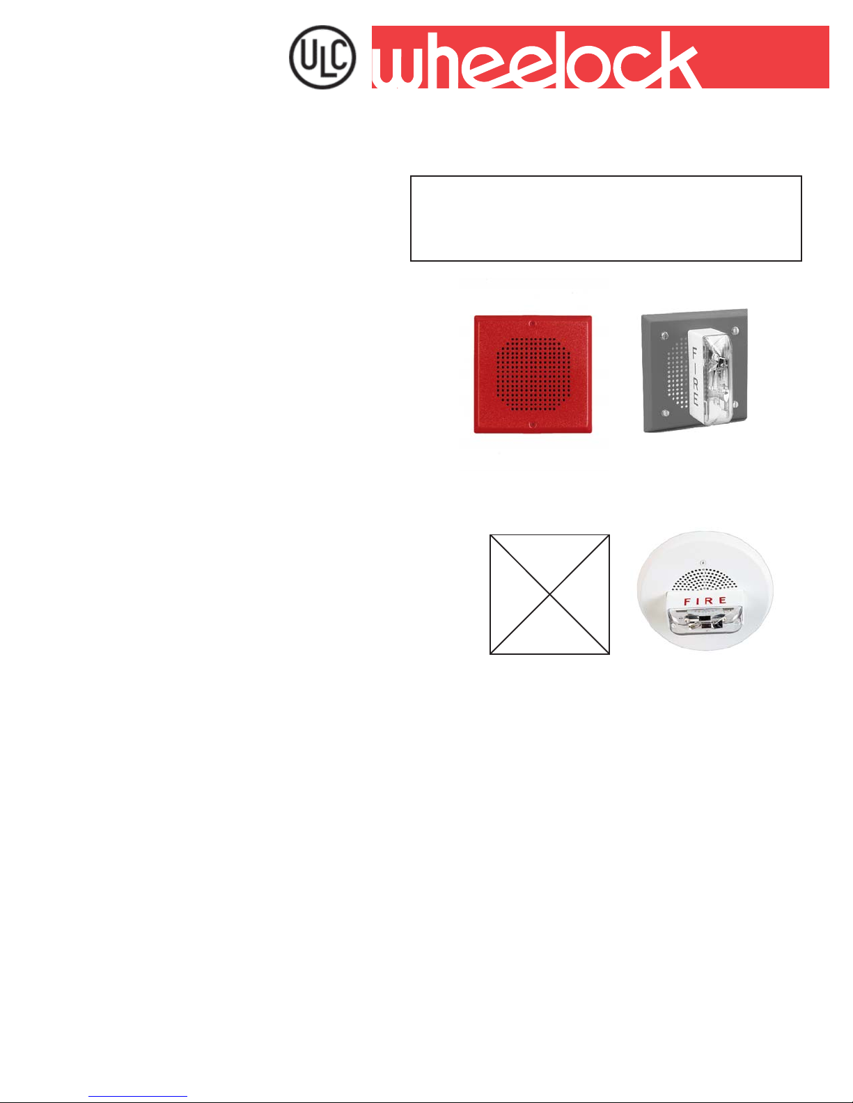
SERIES E LOW PROFILE
SPEAKERS & SPEAKER STROBES
Series E-70 + LS
SM
Features
• Approvals include: CAN/ULC-S541-99 for speaker appliances and
CAN/ULC-S526-02 for visual appliances.
• High efficiency speakers designed for maximum output at minimum
wattage across a frequency range of 400 to 4000 Hz
• 25 or 70 VRMS models with field selectable taps for operation from 1/8
watt up to 2 watts in 3 dB steps
• Series E Low Profile Speaker S trobe models are available with 15 candela
strobe featuring a wide Listed Volt age range of 20-31 VDC with low current
draw and low temperature compensation to reduce power consumption
and wiring costs
• All audio and strobe inputs ay be supervised with standard reverse polarity
supervision from a Fire Alarm Control Panel (FACP)
• Attractive, compact grille styles for flush mounting to low cost electrical
backboxes or surface mounting to Wheelock’s SBB backbox
• Sealed back speaker construction for extra protection and improved
audibility
• Fast installation with IN/OUT screw terminals using #12 to #18 AWG
wiring
Copyright 2005 Wheelock, Inc. All rights reserved.
Series E-90 + LS
44
Page 2
WARNING: PLEASE READ THESE SPECIFICA TIONS AND INSTRUCTIOS CAREFULL Y BEFORE USING THIS PRODUCT. FAILURE TO
COMPL Y WITH ANY OF THE FOLLOIWNG INSTRUCTIONS, CAUTIONS AND W ARNINGS COULD RESUL T IN IMPROPER APPLICA TIONS,
INSTALLA TION AND/OR OPERA TION OF THESE PRODUCTS IN AN EMERGENCY SITUATION, WHICH COULD RESUL T IN PROPERTY
DAMAGE, SERIOUS INJURY OR DEA TH TO YOU AND/OR OTHERS.
NOTE: All CAUTIONS and W ARNINGS are identified by the symbol . All warnings are printed in bold capit al letters.
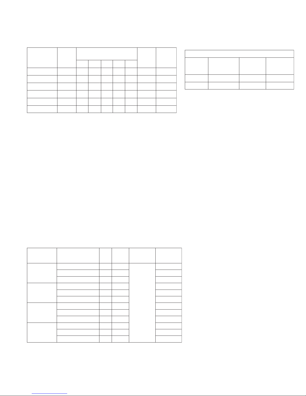
Specifications and Ordering Information
ledoM
5207-E52578
egatloV
)SMRV
8/14/12/112
7184878- 5209-E525787184878- 0707-E075787184878- 0709-E075787184878- -
42-SL-5207-E5257871848784251
42-SL-5209-E5257871848784251
#dBA ratings are based on UL testing under Standard UL 1480
WARNING: AL THOUGH ULC TESTING HAS VERIFIED THA T THESE STROBES FUNCTION EVEN A T 80% OF THEIR MINIMUM RA TING AND
110% OF THEIR MAXIMUM RA TING, WHEELOCK STRONGLY RECOMMENDS THA T THE VOL T AGE APPLIED TO THESE PRODUCTS BE
WITHIN THEIR RATED INPUT VOLTAGE RANGE. THE APPLICATION OF IMPROPER VOLTAGE MA Y RESUL T IN DEGRADED OPERA TION OR
DAMAGE TO THESE PRODUCTS.
The ULC Listed “Rated Input Voltage” uses either filtered (DC) or unfiltered full-wave-rectified (FWR) volt age. Check the minimum and maximum output
of the power supply and standby battery and subtract the voltage drop from the circuit wiring resistance to determine the applied voltage to the strobes.
Use the highest value of rated average current to determine the maximum number of strobes and to establish power supplies and wire gauge requirements. Use the rated peak current or rated inrush current (whichever is higher) to verify fuse requirements.
Make sure that the average, peak and inrush currents do not exceed system power supplies or fusing limits. See “Installation Instructions”.
WARNING: CONT ACT WHEELOCK FOR “INST ALLA TION INSTRUCTIONS” AND “GENERAL INFORMA TION” SHEET ON THESE PRODUCTS.
THESE MATERIALS CONT AIN IMPORT ANT INFORMA TION THA T SHOULD BE READ PRIOR T O SPECIFYING OR INST ALLING THESE
PRODUCTS, INCLUDING:
• TOT AL CURRENT REQUIRED BY ALL APPLIANCES CONNECTED T O SYSTEM SECONDARY POWER SOURCES
• FUSE RATINGS ON NAC CIRCUITS T O HANDLE MAXIMUM INRUSH OR PEAK CURRENTS FROM ALL APPLIANCES ON THOSE NAC
CIRCUITS. THE TIME DURATION OF THE MAXIMUM STROBE INRUSH OR PEAK CURRENT IS 2 MILLISECONDS FOR LS
• INST ALLATION IN OFFICE AREAS AND OTHER SPECIFICATION AND INSTALLA TION ISSUES
General Notes:
• Strobes are designed to falsh at 1 flash per second minimum
• Series E Speaker Strobes are Listed for indoor use with a temperature range of 0°C to 49°C (32°F to 120°F) and maximum humidity of 95%RH.
WARNING: USE STROBES ONL Y ON NAC CIRCUITS WITH CONTINUOUSLY APPLIED OPERATING VOLTAGE. DO NOT USE STROBES ON
CODED OR INTERRUPTED NAC CIRCUITS IN WHICH THE APPLIED VOL T AGE IS CYCLED ON AND OFF , AS THE STROBE MA Y NOT FLASH.
rekaepS
teeF01taABdrekaepS
#)sttaWdetaR(
ebortS
egatloV
)CDV(
ebortS
alednaC
egatloV
2080.091.052.
CDV4
egarevAdetaR
tnerruC
SL
SL
)SPMA(stnemeriuqeRtnerruCebortS
kaePdetaR
tnerruC
SL
RWFV42180.612.083.
Note: All VFWR voltages in table are measued with DC volt
meter. Multiply VFWR voltage by 1.1 1 to convert to VRMS.
hsurnIdetaR
tnerruC
Ordering Information
seireSrebmuNledoM
52srekaepSE
SMRV
07srekaepSE
SMRV
rekaepSE
SMRV52sebortS
rekaepSE
SMRV07sebortS
*Average Current per actual Wheelock Production T esting @ 24 VDC nominal. For rated average, peak and inrush across the listed voltage range for
both filtered DC and full-wave-rectified (FWR), see installation instructions.
**Refer to Data Sheet #S7000 for mounting options. WARNING: SERIES E SPEAKERS DO NOT FIT ALL CANADIAN EXTENSION RINGS. Call
factory for assistance. (Example if Extension Ring Manufacturer that fits is TEMCO).
Speaker Notes: 1. Series E speakers have separate 25 VRMS and 70 VRMS models. All Seires E models have field selectable tap s for 1/8, 1/4, 1/2, 1,
or 2 watt operation. 2. Models code suffix V= vertical lens; C= ceiling lens; F= fire lettering; R= red plate; W= white plate. 3. Approval codes: ULC=
Underwriter Laboratories of Canada.
45
CLU-R-5207-E2874-
CLU-W-5207-E3494- CLU-W-5209-E4374- -
CLU-R-0707-E0424- -
CLU-W-0709-E9324- CLU-W-0707-E14
CLU-WFC-42-SL-5209-E23365147.0
CLU-RFV-42-SL-5207-E13365147.0
CLU-WFV-42-SL-5207-E8028514
CLU-WFC-42-SL-0709-E71365147.0
CLU-RFV-42-SL-0707-E61365147.0
CLU-WFV-42-SL-0707-E60775
redrO
edoC
24- -
ebortS
alednaC
147.0
ABdrekaepS
teeF01ta
)09-18(
earevA
42@tnerruC
*CDV
-
7.0
Page 3

Wiring Diagrams
SERIES E SPEAKER & STROBE OPERATE
INDEPENDENTLY (NON-SYNC OR SYNC)
FROM
PRECEDING
APPLIANCE
OR VOICE
EVACUATION
PANEL
FROM
PRECEDING
STROBE, SYNC
MODULE, POWER
SUPPLY OR
FACP
+
++
-
-
-
+
STROBE
+
-
SPEAKER
TO NEXT
+
APPLIANCE
-
OR EOLR
TO NEXT
STROBE OR
-
EOLR
Application Notes:
CAUTION: Check that the installed product will have sufficient clearance and wiring room prior to installing backboxes and conduit, especially if
sheathed multiconductor cable or 3/4” conduit fittings are used.
1. Mounting hardware for each mounting option is supplied.
2. Conduit entrances to the backbox should be selected to provide sufficient wiring clearance for the installed product. When extension rings are
required, conduit should enter through the backbox, not the extension ring. Note not all Canadian Extension Rings fit Series E. Call factory for
assistance.
3. When terminating field wires, do not use more lead length than required. Excess lead length could result in insufficient wiring space for the signaling
device.
4. Use care and proper techniques to position the field wires in the backbox so that they use minimum space and produce minimum stress on the
product. This is especially important for stiff, heavy gauge wires and wires with thick insulation or sheathing.
5. Do not pass additional wires (used for other than the signaling device) through the backbox. Such additional wires could result in insufficient wiring
space for the signaling appliance.
6. Frequency range of speakers is 400-4000 Hz.
7. A blocking capacitor for DC supervision of audio lines by the F ACP is factory wired in series with the speaker input 1.5uF for 25 VRMS speakers
and 0.15uF for 70 VRMS speakers.
CAUTION: Always operate audio amplifiers and speakers within their specified ratings. Excessive input may distort sound quality and may damage
audio equipment. Do not exceed =130% of speaker rated voltage per CS 243. Improper input voltage can damage speaker . If distortion is heard, check
for clipping of the audio signal with an oscilloscope and reduce the amplifier input level or gain level to eliminate any clipping.
CEILING FLUSH MOUNTING
Circular Backbox for 4”
Speaker available in
Canada only
Series
ET-1090
By Others (BO)
Wheelock products must be used within their published specification and must be properly specified, applied , installed, operated,
maintained and operationally tested in accordance with their installation instruction at the time of installation and at least twice a year or
more often and in accordance with local, state, and federal codes, regulations and laws. S pecification, application, installation,
operation, maintenance and testing must be performed by qualified personnel for proper operation in accordance with all of the latest
National Fire Protection Association (NFP A), Underwriters’ Laboratories (UL & ULC), local, state, county , province, district, federal and
other applicable building and fire standards, guidelines, regulations, laws and codes including, but not limited to all appendices and
amendments an the requirements of local authority having jurisdiction (AHJ).
Due to continuous development of our products, specifications and offering are subject to change without notice in accordance with
Wheelock, Inc. standard terms and conditions.
WARNING! PLEASE DO NOTE THAT THE E SERIES DO NOT FIT ALL CANADIAN EXTENSION RINGS.
46
Page 4

Architects and Engineers Specifications
The speaker appliance shall be a Wheelock Series E low profile speaker and speaker strobe appliance or equivalent.
The speaker and strobes shall be ULC Listed under CAN/ULC-S541-99 and CAN/ULC-S526-02 for Fire Protective
Service. All speakers shall be either 25 or 70 VRMS inputs with field selectable power taps from 1/8 to 2 watts with
Listed sound output up to 90 dBA at 10 feet, and a listed frequency response of 400 to 4000 Hz. Strobes shall use
filtered power or unfiltered power supply (full-wave-rectified). All models shall have provisions for standard reverse
polarity type supervision and IN/OUT field wiring using terminals that accept #12 to #18 AWG wiring.
Combination speaker strobe appliances signals shall incorporate a Xenon flashtube enclosed in a rugged Lexan lens
or equivalent with solid state circuitry. Strobe shall meet ULC and produce a flash rate of one (1) flash per second
minimum over the Listed input voltage range (20-31 VDC). The strobe intensity shall be rated per ULC for 15
candela. The strobe shall be certified to meet FCC Part 15 Class B and shall incorporate low temperature compensation
to insure lowest possible current consumption.
The combination speaker strobe appliances shall be installed indoors and surface or flush mounted. They shall
mount to standard electrical hardware requiring no additional trimplate or adapter . The appliance shall be finished in
a textured red or white color.
WE ENCOURAGE AND SUPPORT NICET CERTIFICATION
National Sales Office
800-631-2148
Canada 800-397-5777
E-Mail: Info@wheelockinc.com
http://www.wheelockinc.com
273 Branchport A venue • Long Branch, NJ 07740 • TEL: 732-222-6880 • FAX: 732-222-2588
47
3 YEAR WARRANTY
ASSEMBLED IN THE USA
Distributed By:
S1610C 02/05
 Loading...