

Page 1
FIRE ALARM SYSTEMS
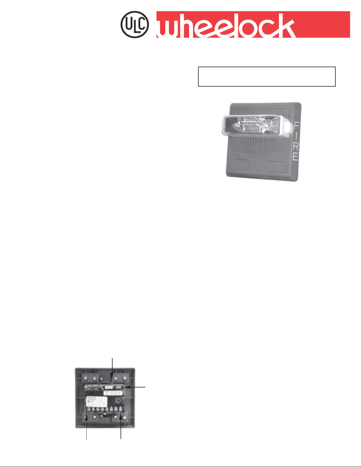
Description
WHEELOCK’S Series AMT Multiple Input Electronic
Appliances provide the industry with a ULC combination
audible/visual appliance that simplifies installation and
offers three (3) distinct prioritized audible signals from
three isolated inputs. Priority (1) will override all other
commands upon activation.
The AMT offers a choice of eight (8) self-prioritized sound
combinations for suppression releasing systems,
combination security and emergency evacuation
systems and high risk installations as well as many
other applications.
Each AMT Audible and AMT S trobe appliance has two
user selective sound output levels: Standard dBA and
High dBA. The AMT Audible provides 12VDC or 24VDC
operation, filtered or FWR. The AMT S trobe Appliances
operate at 24VDC and may be used with filtered or
unfiltered (FWR) input voltages. Separate supervised
sets of input terminals are available for each prioritized
input. Jumper plugs are provided to enable both tone
and strobe to operate simultaneously for all inputs.
The AMT Multitone S trobe Appliances are ULC Listed
under Standard CAN/ULC-S526-02 for V isual Signaling
Appliances and Standard CAN/ULC-S525-99 for Audible
Signaling Appliances and use a Xenon flashtube with
solid state circuitry enclosed in a rugged Lexan® lens
to provide maximum reliability for effective visible
signaling.
All models may be synchronized when used in
conjunction with the Wheelock SM or DSM Sync
Modules, with patented Sync Protocol.
Synchronization of the continuous horn tone provides
the temporal (Code 3) tone as mandated by NFP A-72
for all audible appliances. This ensures a distinct
temporal (Code 3) pattern when 2 or more audibles are
within hearing distance. If not synchronized, the
temporal sound may overlap and not be distinctive. At
the same time, the strobes will also be synchronized.
This provides the ability to comply with ADA
recommendations concerning photosensitive epilepsy
and NFPA and UFC standards when installing tow or
more visual appliances within the field of view.
Tone Group Selection
INC.
Helping People Take Action
SERIES AMT AND AMT STROBE
MUL TITONE ELECTRONIC APPLIANCES
SERIES AMT
Features
• Approvals include: CAN/ULC-S526-02 for Visual Signaling
Appliances and Standard CAN/ULC-S525-99 for Audible
Signal Appliances
• Designed to meet or exceed NFPA/ANSI Standards and ADA
Accessibility Guidelines. Meets OSHA 29 Parts 1910.165
• Three separate prioritized inputs that will activate three
isolated signals
• All inputs are supervised
• Code-3 Horn and Tone meet ANSI/NFP A/ISO temporal p attern.
• Two power taps for High dBA and Standard dBA @ 10 feet
• AMT Strobe models available with 15/75 and 75 candela
ratings for independent or combination input activations
• AMT with strobe can flash independently or in unison with all
audible signals
• Selectable input voltage (12 or 24 VDC) for non-strobe
applications
• Polarized inputs for compatibility with standard reverse
polarity type supervision of circuit wiring by an alarm panel.
• Low cost installation via standard electrical boxes. Attractive
flush or surface mounting options
• No additional trimplate required for flush mounting. Fast
installation with In/Out screw terminals using #12 to #18 AWG
SM
Input Commands
Copyright 2005 Wheelock, Inc. All rights reserved.
Voltage
Selection
18
Page 2
General:
The Series AMT Multitone Strobe Appliances are ULC Listed under Standard CAN/ULC-S525-99 for Visual Signaling Appliances
and Standard CAN/ULC-S526-02 for Audible Signaling Appliances for Fire Alram Systems for indoor use with a temperature range
of 0°C to 49°C (32°F to 49°F). They are listed for indoor only use with the backboxes specified in these instructions (See Mounting
Options). The AMT Multitone Strobe signals use a Xenon flashtube with solid state circuitry enclosed in a rugged Lexan
provide maximum visibility and reliability for effective visible signaling.
NOTE: All CAUTIONS and WARNINGS are identified by the symbol . All warnings are printed in bold capital letters.
WARNING: PLEASE READ THESE INSTRUCTIONS CAREFULLY BEFORE USING THIS PRODUCT. FAILURE TO COMPLY
WITH ANY OF THE FOLLOWING INSTRUCTIONS, CAUTIONS AND WARNINGS COULD RESULT IN IMPROPER
APPLICA TION, INSTALLA TION AND/OR OPERA TION OF THESE PRODUCTS IN AN EMERGENCY SITUATION, WHICH COULD
RESULT IN PROPERTY DAMAGE, SERIOUS INJURY OR DEA TH TO YOU AND/OR OTHERS.
slangiSelbiduAenotitluMTMArofsgnitaRtnerruC:1elbaT
egarevAdetaR
enoTnoitpircseDenoT
nroH)suounitnoc(nroHdnabdaorB640.520.001.020
*lleB)taepeR/nO.ceS70.0(detaludoMzH0651810.410.130.010.
nroHemiThcraM)taepeR/ffO.ceS52.0/NO.ceS52.0(nroH640.5
nroH3-edoC)nrettaPlaropmeT14.3SISNA(nroH640.520.001.020.
enoT3-edoC)nrettaPlaropmeT14.3SISNA(zH00572
poohWwolS)taepeR/FFOceS5.0/nO.ceS0.4(peewSzH0021-005340.520.001.520.
neriS)taepeR/nO.ceS0.1(peewS
OL/IH)etanretlA/nO.ceS52.0(xH008/0001220.610.440.310.
emihCgnitarbiV)taepeR,yaceD.ceS0
zH0021-006730.910.280.020.
.1(zH007310.010.720.010.
A-CDV
ABdIHABdDTSABdIHABdDTS
0.410.060.510.
42)SPMA(tnerruC
elbidu
20.001.020.
egarevAdetaR
21)SPMA(tnerruC
elbiduA-CDV
.
®
lens to
sgnitaRABdLU:2elbaT
tnarebreveRABd
enoT
OL/IH
emuloV
464LUrePsgnitaR
sgnitaR
V42V42
IH2989
nroH
DTS6829
IH4819
ll
eB
DTS8768
IH8889
emiThcraM
DTS2829
IH8889
nroH3edoC
DTS1829
IH4849
enoT3edoC
DTS8798
IH8889
poohWwolS
DTS3839
IH9879
neriS
Add 25% more input current than shown in Table 1 when operating
the unit at maximum input voltage.
ciohcenAABd
Add average strobe current from Table 4 to average audible current
from Table 1 to obtain total average current for each unit, if the strobe
and audible are wired to operate in unison on a single circuit.
Wheelock’s AMT Appliances are unique multitone alarm signals with
separate input terminals for each sound. They are the ideal choice for
suppression systems and emergency signaling systems where
distinctive multiple alarm conditions are required. Eight groups of
three self-prioritized sound outputs are provided with separate electrically isolated input terminals for each sound (see Table 2 and Table
5 for sound selections). Sound output can be field set to provide either
HIGH (HI) dBA or STANDARD (STD) dBA sound output level.
All AMT Multitone Strobe models are designed for use with either
filtered or unfiltered Full-Wave-Rectified (FWR) input voltage. The AMT
Multitone Strobe Appliances have separate input terminals for alarm
tone activation and strobe activation. The strobes can be easily field
programmed to operate independently or in unison with all of the
audible alarms. All inputs are polarized for compatibility with standard
reverse polarity supervision of circuit wiring by a Fire Alarm Control
Panel (FACP). In the event that three simultaneous commands occur,
priority one will activate. If priority 2 + priority 3 exist, priority 2 will
activate.
DTS3829
IH6829
OL/I
H
DTS1878
IH8788
emihC
DTS1728
Anechoic dBA is measured on axis in a non-reflective (free field) test room using fast meter response. For peak dBA (measured with
peak meter response), add 5 dBA to typical anechoic values shown in Table 2. Reverberant dBA is a minimum UL rating based on
sound power measurements in a reverberant test room.
19
Page 3

noitamrofnInoitacificepSdnagniredrO:3elbaT
rebmuNledoM
R-42/21-TMA788542/21- - R,P,O,N,M,L,F,E,D
W-42/21-TMA398542/21- - R,P,O,N,M,L,F,E,
RF-W575142-TMA36494257/51270.0R,P,O,N,M,L,F,E,D
WF-W575142-TMA66494257/51270.0R,P,O,N,M,L,F,E,D
RF-WCM42-TMA0033420
WF-WCM42-TMA203342011/57/03/51041./901./360./140.R,P,O,N,M,L,
* Average current per Wheelock Production Testing at 12/24 VDC nominal voltage. For rated average, peak and in-rush current across the UL listed
voltage range for both filtered DC and full wave rectified FWR refer to table above.
** Mounting Options: Refer to Data Sheet S7000 or current catalog for mounting options.
redrO
edoC
tupnI
egatloV
detaR
alednaC
11/57/03/51041./901./360./140.R,P,O,N,M,L,F,E,D
ebortS*egarevA
)
SPMA(CDV42tnerruC
**snoitpOgnitnuoM
D
F,E,D
The ULC Listed “Rated Voltage’’ range is 20-31 VDC for 24 VDC models and 10.5-15.6 VDC for 12 VDC audible only model using
either filtered (DC) or unfiltered full-wave-rectified (FWR) voltage. Check the minimum and maximum output of the power supply
and standby battery and subtract the voltage drop from the circuit wiring resistance to determine the applied voltage to the
notification appliance.
WARNING: ALTHOUGH UL TESTING HAS VERIFIED THAT THESE PRODUCTS FUNCTION EVEN AT 80% OF THEIR MINIMUM RATING AND
110% OF THEIR MAXIMUM RA TING, WHEELOCK STRONGLY RECOMMENDS THA T THE VOL T AGE APPLIED T O THESE PRODUCTS BE WITHIN
THEIR RATED VOLTAGE RANGE. THE APPLICATION OF IMPROPER VOLTAGE MAY RESULT IN DEGRADED OPERATION OR DAMAGE TO
THESE PRODUCTS.
WARNING: MAKE SURE THAT THE TOTAL CURRENT REQUIRED BY ALL APPLIANCES THAT ARE CONNECTED TO THE SYSTEM’S
PRIMARY AND SECONDARY POWER SOURCES AND NAC CIRCUITS DOES NOT EXCEED THEIR RATED CURRENT. OVERLOADING THESE
SOURCES COULD RESULT IN LOSS OF POWER AND FAILURE T O ALERT OCCUPANTS DURING AN EMERGENCY.
WARNING: MAKE SURE THA T ALL FUSES USED ON NAC CIRCUITS ARE RA TED T O HANDLE THE MAXIMUM INRUSH OR PEAK CURRENT
FROM ALL APPLIANCES ON THOSE CIRCUITS. FAILURE TO DO THIS MAY RESULT IN LOSS OF POWER TO THE NAC CIRCUIT AND THE
FAILURE OF ALL APPLIANCES ON THAT CIRCUIT TO OPERATE.
WARNING: THE STROBES ARE DESIGNED TO FLASH AS SPECIFIED WITH CONTINUOUS (NON-CODED) APPLIED VOLT AGE. THE STROBES MAY
NOT FLASH IF USED IN CODED SYSTEMS.
AMT Multitone strobe models are UL Listed for indoor use with a temperature range of 0°C to 49°C (32°F to 120°F) and maximum
humidity of 85%.
NOTE: This equipment has been tested and found to comply with the limits for a Class B digital device, pursuant to Part 15 of the
FCC Rules. These limits are designed to provide reasonable protection against harmful interference in residential installation.
This equipment generates, uses and can radiate radio frequency energy and, if not installed and used in accordance with the
instructions, may cause harmful interference to radio communications. However, there is no guarantee that interference will not
occur in a particular installation. If this equipment does cause harmful interference to radio or television reception, which can be
determined by turning the equipment off and on, the user is encouraged to try to correct the interference by one or more of the
following measures: 1) Reorient or relocate the receiving antenna, 2) Increase the separation between the equipment and receiver,
3) Connect the equipment into an outlet on a circuit different from that to which the receiver is connected, and 4) Consult the dealer
or an experienced radio/TV technician for help.
AMT Multitone Strobe Appliances are field set for any one of eight groups of self-prioritized tones by setting a four position switch
(SW1) as shown in Table 4. Use SW1 POS 2,3,4 to select the desired alarm tones.
Note: The prioritized tones contained in each group is factory pre-set which can not be changed.
5elbaT
senoTsgnitteShctiwS
1IRP2IRP3IRP2SOP3SOP4SOP
nroHlleBneriS 111
nroH3edoCneriSemihCgnitarbiV101
poohWwolSnroHemiThcraMO
nroHemiThcraMOL/IHemihCgnitarbiV110
nroH3edoClleBneriS011
neriSnroHemihCgnitarbiV010
lleBnroHemiThcraMneriS100
enoT3edoCOL/IHneriS 000
L/IH001
detaR
tnerruC
CDV42RWFV42
egatloV
egarevA080.180.
kaeP091612.
hsurnI052.083.
stnemeriuqeRtnerruCebortS:4elbaT
Note: The Code-3 Horn and Code-3 Tone (set on HIGH dBA) incorporate the temporal pattern specified by ANSI/NFPA for st andard
emergency evacuation signaling. They should be used only for fire evacuation signaling and not for any other purpose.
The Horn and Bell Tones can be used on coded systems with a minimum On-Time of 1/4 second if the audible and strobe are wired
to operate independently. All other tones are recommended for use only on continuous (non-coded) systems.
20
Page 4

Architects and Engineers Specifications
When notification appliances are required for applications with more than one function, an appliance with multiple inputs and
capable of being programmed shall be used. The notification appliance shall be capable of accepting three (3) individual DC
signals and providing three (3) distinct audible signals. In the event the signals are simultaneous, the priority shall be as follows.
Highest priority = PR1, Second priority = PR2 and the Third priority = PR3. With the addition of the Strobe, the appliance shall operate with
an independent input DC voltage to the strobe terminals. When it is desired to operate the strobe with all of the audible signals, only
a set of jumpers shall be required.
The notification appliance shall be a Wheelock Series AMT audible/visual appliance or equivalent. Notification appliance shall be
electronic and use solid state components. Electromechanical alternatives are not approved. Tone selection shall be by durable dip
switch assembly and not clips or jumpers. The audible and the strobe shall be able to operate from a single NAC circuit while
producing any of these tones. The appliances shall provide two output sound levels: Standard and High dBA. The High anechoic dBA
measurement at 10 feet at the alarm HORN SETTING shall be 98 dBA for AMT and 98 dBA for AMT Strobes, at nominal voltage.
Operating voltages shall be either 12VDC (Audible only) or 24VDC using filtered power or unfiltered power supply (FWR). All models
shall have provisions for standard reverse polarity type supervision and IN/OUT field wiring using terminals that accept #12 to #18
AWG wiring.
Combination audible/visual appliances shall incorporate a Xenon flashtube enclosed in a rugged Lexan lens or equivalent with
solid state circuitry. Strobe shall meet ULC Listed under Standard CAN/ULC-S526-02 for Visual Signaling Appliances and Standard
CAN/ULC-S525-99 for Audible Signaling Appliances
The combination audible/visual appliances may be installed indoors and surface or flush mounted. They shall mount to standard
electrical hardware requiring no additional trimplate or adapter. The aesthetic appearance shall not have any mounting holes or
screw heads visible when the installation is completed. The appliance shall be finished in a textured red color.
The audible appliance may be installed indoor or outdoor with the proper backbox.
Strobe models shall incorporate circuitry for synchronizated strobe flash and shall be designed for compatibility with Wheelock SM
and/or DSM Sync Modules with Sync Protocol. The strobes shall not drift out of synchronization at any time during operation. If the
module fails to operate (i.e., contacts remain closed), the strobes shall revert to a non-synchronized default flash rate.
Wiring Diagrams (for all models)
• Isolated inputs are provided for independent supervision and
actuation of the three audible inputs.
• In case of simultaneous inputs, the three audible outputs are
self-prioritized as follows: 1st priority = PRI 1; 2nd priority = PRI 2,
3rd priority = PRI 3. (See table 4 for tone selection).
• Leave any unused inputs disconnected.
• For applications not requiring supervision: connect all positive (+)
terminals to the power source. The negative (-) terminal for each
signal will actuate the device.
Unsupervised System
Common Negative
PRI 1PRI 2PRI 3STROBE
-
++++
COMMON
NEGATIVE
V
FROM PRECED ING
SIGNAL OR FIRE
ALARM CONTROL
PANEL (F.A.C.P.)
VVVV
1. AMT Multitone appliances have in-out wiring terminals that
accept two #12 to #18 American Wire Gauge (AWG) wires at each
screw terminal. Strip leads 3/8 inches and connect to screw
terminals.
WARNING: NFPA CODES REQUIRE SIGNALING
APPLIANCES TO BE SUPERVISED. CHECK TO BE CERTAIN
THAT UNSUPERVISED SIGNALING APPLIANCES DO NOT
VIOLATE ANY APPLICABLE CODES.
---
COMMON
NEGATIVE
TO NEXT
SIGNAL OR
END-OF-LINE
RESISTOR
(E.O.L.R.)
Supervised System
PRI 1PRI 2PRI 3STROBE
-
---
Unsupervised System
Common Positive
-
---
COMMON
POSITIVE
TO NEXT
SIGNAL OR
END-OF-LINE
RESISTOR
(E.O.L.R. )
TO NEXT
SIGNAL OR
END-OF-LINE
RESISTOR
(E.O.L.R.)
FROM PRECEDING
SIGNAL OR FIRE
ALARM CONTROL
PANEL (F.A.C.P.)
FROM PR EC EDIN G
SIGNAL OR FIRE
ALARM CONTROL
PANEL (F.A .C.P.)
++++
V
V
VV
V
V
VV
PRI 1 PRI 2 PRI 3 STROBE
++++
COMMON
POSITIVE
V
V
V
VV
2. Break all in-out wire runs on supervised circuits to assure integrity
of circuit supervision as shown on left. The polarity shown in the
wiring diagrams is for operation of the appliance. The polarity is
reversed by the F.A.C.P. during supervision.
NOTE: Due to continuous development of our products, specifications and offerings are subject to change without notice in
accordance with Wheelock Inc. standard terms and conditions.
WE SUPPORT AND ENCOURAGE NICET CERTIFICATION
Distributed By:
S4000C 02/05
NATIONAL SALES OFFICE
800-631-2148
Canada 800-397-5777
E-Mail: Info@wheelockinc.com
http://www.wheelockinc.com
273 BRANCHPORT AVENUE • LONG BRANCH, NJ 07740 • TEL: 732-222-6880 • FAX: 732-222-2588
21
ASSEMBLED IN THE USA
3 YEAR WARRANTY
 Loading...