

Wheelock Series RSSP, SS-121575W-FW, AGP-1000, SS-121575W-FR, SS-121575W-NW Specification
...Page 1
FIRE ALARM SYSTEMS
DESCRIPTION
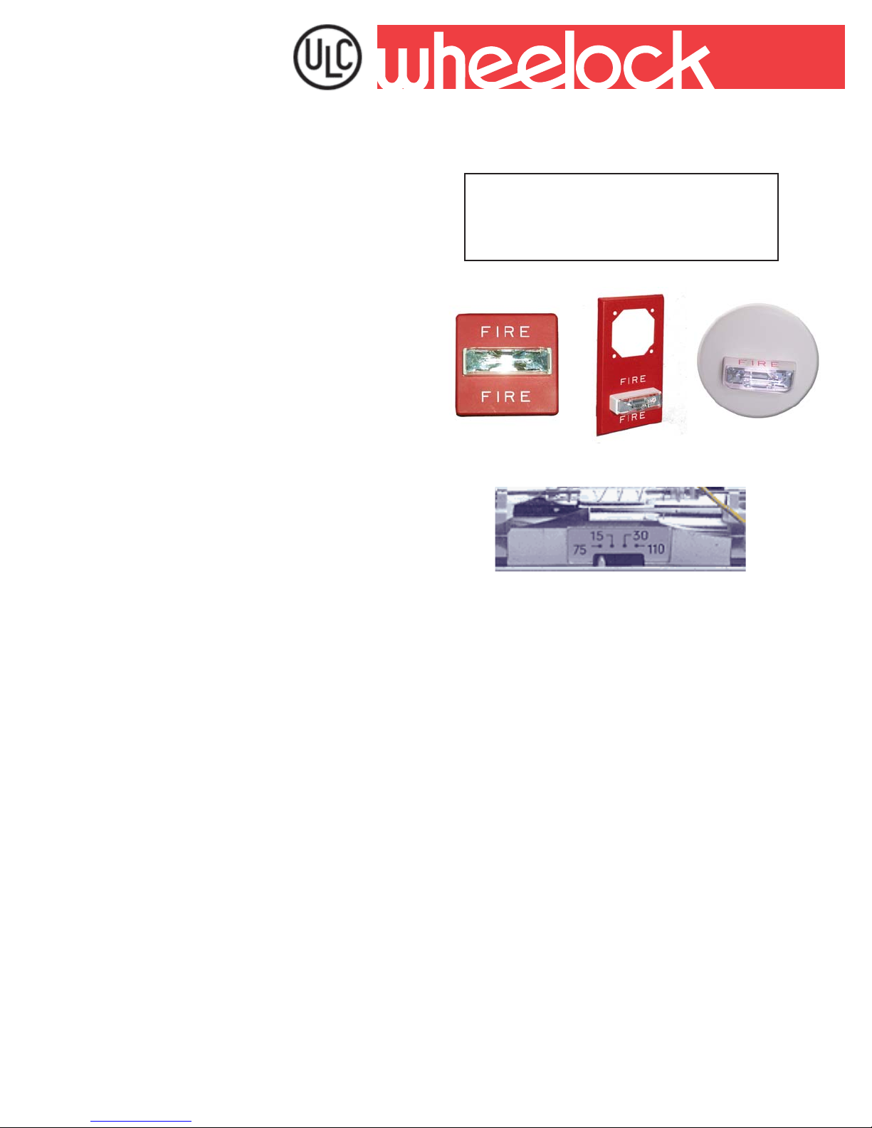
Wheelock’s patented Series RSS S trobe Appliances and
Series RSSP S trobe Plates have lower current draw while
maintaining outstanding performance, reliability and cost
effectiveness. These versatile appliances will satisfy
virtually all requirements for indoor, wall or ceiling mount
applications.
Helping People Take Action
SERIES RSS & RSSP SINGLE
& MULTI-CANDELA STROBES
& STROBE PLATES
Series RSS
Series RSSP
INC.
SM
RSS Round
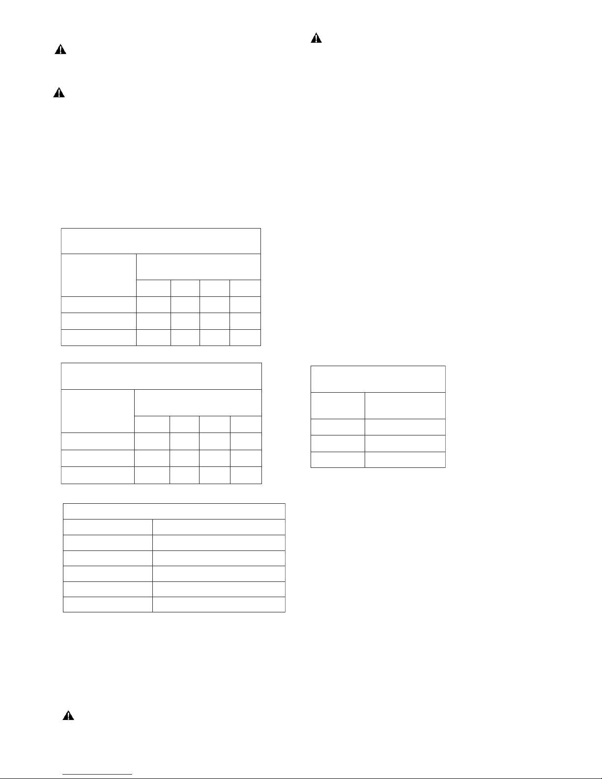
Strobe options for wall mount models include Wheelock’ s
patented Multi-Candela strobe with field selectable candela
settings of: 15, 30, 75 or 110cd. Ceiling mount models
are available in 15, 30, 75 or 100cd intensities.
All models may be synchronized when used in conjunction
with the Wheelock SM or DSM Sync Module(s).
Synchronized strobes can eliminate possible restrictions
on the number of strobes in the field of view. Wheelock’ s
synchronized strobes offer an easy way to comply with
recommendations concerning photosensitive epilepsy .
Wheelock’s Series RSS Strobes employ a Patented
Integral Strobe Mounting Plate that can be mounted to a
single gang, double gang, 4” square, 100mm European
backboxes or the SHBB surface backbox. If the flush
backbox has side or top space between it and the finished
wall, the NA TP (Notification Appliance Trimplate) may be
used. It provides an additional .65” of trim for the Appliance.
An attractive cover plate is provided for a clean, finished
appearance on all models.
The Series RSSP Multi-Candela Strobe Plates are a cost
effective way to retrofit required strobe appliances to bells,
horns, chimes, multitones or speakers and easily mounts
to standard 4” backboxes or for surface mount use with
Wheelock’s SBL2 surface backbox.
For Weatherproof Strobe See Datatsheet
S9004C for RSSWP-2475W-FR.
Copyright 2005 Wheelock, Inc. All rights reserved.
Multi-Candela Indicator
(bottom of Strobe Lens)
Features
• Approvals include: CAN/ULC-S5206-02 for Visual
Signaling Appliances. FCC Part 15 Class B
• ADA/NFPA/ANSI compliant
• Meets OSHA 29 Part 1910.165
• Wall mount models are available with Field
Selectable Candela Settings of 15, 30, 75 or
110 cd. (Multi-Candela models)
• Ceiling mount models are available in 15, 30,
75 or 95cd
• Low current draw with temperature compensation
to reduce power consumption and wiring costs.
• Strobes produce 1 flash per second over the
regulated voltage range
• 12 and 24 VDC models with wide ULC Listed Volt age
using filtered DC or unfiltered VRMS input voltage
• Wall Mount or Ceiling Mount models
• Synchronize with Wheelock SM or DSM sync
module(s)
• ZERO Inrush above Peak
• Compatible with all Wheelock 2-Wire products
• Fast installation with IN/OUT screw terminals
using #12 to #18 A WG wire
24
Page 2
NOTE: All CAUTIONS and WARNINGS are identified by the symbol . All warnings are printed in bold capital letters.
WARNING: PLEASE READ THESE SPECIFICA TIONS AND ASSOCIA TED INST ALLA TION INSTRUCTIONS CAREFULL Y BEFORE USING ,
SPECIFYING OR APPL YING THIS PRODUCT. FAILURE TO COMPL Y WITH ANY OF THESE INSTRUCTIONS, CAUTIONS OR W ARNINGS
COULD RESULT IN IMPROPER APPLICA TION, INST ALLA TION AND/OR OPERATION OF THESE PRODUCTS IN AN EMERGENCY SITUATION,
WHICH COULD RESULT IN PROPERTY DAMAGE, AND SERIOUS INJUR Y OR DEA TH TO YOU AND/OR OTHERS.
WARNING: FOR ULC APPLICA TIONS THESE APPLIANCES WERE TESTED TO THE OPERATING VOLT AGE LIMITS OF 20-31 VOLTS/
USING FILTERED (DC) OR UNFIL TERED FULL-W A VE RECTIFIED (FWR). APPLY 80% AND 1 10% OF THESE V ALUES FOR SYSTEM OPERATION.
General Notes
• Strobes are designed to flash at 1 flash per second minimum over the Voltage Range.
• All candela ratings represent minimum effective Strobe intensity based on UL 1971.
• Series RSS & RSSP Strobe products are listed under CAN/ULC-S526-M87 for indoor use with a temperature range of 0° C to 49° C (32° F to
120° F) and maximum humidity of 93% (± 2%).
• All Canadian Installations should be in accordance with the Canadian Standard for the Installation of Fire Alarm Systems -
CAN/ULC-S524-01 and Canadian Electrical Code, Part 1.
SsetalPebortSPSSRdnaebortSSSRseire
egatloV
CDV0.02060.290.561.022.
CDV0.42140.360.901.041.
CDV0.13330.740.180.001.
SsetalPebortSPSSRdnaebortSSSRseire
egatloV
CDV0.02560.501.981.942.
CDV0.42540.070.911.951.
CDV0.13530.250.980.011.
snroHHN,HA
slleBrotoM01G/6
srekaepS0707/5207E,0801/0701/0101-TE
semihC07HC
rof)SPMA(tnerruCCLU:1elbaTtnuoMllaW-
@detaR
dc51dc03dc57dc011
rof)SPMA(tnerruCCLU:2elbaTtnuoMgnilieC
V42@detaR
dc51dc03dc57dc59
tcudorPseireS
secnailppAenotitluMTM,TMA
G-BM
* Average Current per actual Wheelock
Production testing at listed VDC.
*tnerruCegarevA
CDV21roCDV42
# U= FIRE/FEU lettering
Note: Models are available in either Red
or White.
Contact Customer Service for Order
Code and Delivery.
Note: Installation Instruction Sheets:
Series RSS/RSSP - Wall Mount
Multi-Candela (P83911); Series RSS
Ceiling Mount (P84025).
)SPMA(tnerruCCLU:4elbaT
PWSSRseireSrof
*tnerruCegarevA
CDV21roCD
egatloV
*tnerruCegarevA
CDV42@detaR
CDV0.02831.
CDV0.42490.
CDV0.13760.
etalPebortSPSSRrofsrekaepS/selbiduA:3elbaT
WARNING: FOR ULC APPLICA TIONS THESE APPLIANCES WERE TESTED T O THE OPERA TING VOL T AGE LIMITS OF 20-31 VOL TS/
USING FIL TERED (DC) OR UNFILTERED FULL-W A VE RECTIFIED (FWR). APPLY 80% AND 110% OF THESE V ALUES FOR SYSTEM
OPERATION.
25
Page 3

WARNING: CONTACT WHEELOCK FOR THE CURRENT “INSTALLATION INSTRUCTIONS” (P83911) SERIES RSS/RSSP-24MCW, (P84025) SERIES
RSS/RSSP SINGLE CANDELA AND “GENERAL INFORMA TION” SHEET (P82380) ON THESE PRODUCTS. THESE DOCUMENTS UNDERGO PERIODIC
CHANGES. IT IS IMPORTANT THA T YOU HA VE CURRENT INFORMATION ON THESE PRODUCTS. THESE MA TERIALS CONT AIN IMPORT ANT INFORMA TION THA T
SHOULD BE READ PRIOR TO SPECIFYING OR INSTALLING THESE PRODUCTS, INCLUDING:
• TOTA L CURRENT REQUIRED BY ALL APPLIANCES CONNECTED T O SYSTEM SECONDARY POWER SOURCES.
• FUSE RATINGS ON NOTIFICATION APPLIANCE CIRCUITS TO HANDLE PEAK CURRENTS FROM AL L APPLIANCES ON THOSE CIRCUITS.
• ADDING , REPLACING OR CHANGING APPLIANCES OR CHANGING CANDELA SETTINGS WILL EFFECT CURRENT DRAW. RECALCULATE CURRENT
DRAW TO INSURE THAT THE TOTAL AVERAGE CURRENT AND TOTAL PEAK REQUIRED BY ALL APPLIANCES DO NOT EXCEED THE RATED
CAPACITY OF THE POWER SOURCE OR FUSES.
• COMPOSITE FLASH RATE FROM MULTIPLE STROBES WITHIN A PERSON’S FIELD OF VIEW.
• THE VOLT AGE APPLIED TO THESE PRODUCTS MUST BE WITHIN THEIR VOLT AGE RANGE.
• INSTALLATION OF 110 CANDELA STROBE PRODUCTS IN SLEEPING AREAS.
• INSTALLATION IN OFFICE AREAS AND OTHER SPECIFICATION AND INSTALLATION ISSUES.
• USE STROBES ONLY ON CIRCUITS WITH CONTINUOUSLY APPLIED OPERATING VOLTAGE. DO NOT USE STROBES ON CODED OR
INTERRUPTED CIRCUITS IN WHICH THE APPLIED VOLTAGE IS CYCLED ON AND OFF AS THE STROBES MAY NOT FLASH.
• FAILURE TO COMPLY WITH THE INSTALLATION INSTRUCTIONS OR GENERAL INFORMATION SHEETS COULD RESULT IN IMPROPER
INSTALLATION, APPLICATION, AND/OR OPERATION OF THESE PRODUCTS IN AN EMERGENCY SITUATION, WHICH COULD RESULT IN PROPERTY
DAMAGE AND SERIOUS INJURY OR DEATH TO YOU AND/OR OTHERS.
• CONDUCTOR SIZE (AWG), LENGTH AND A MPACITY SHOULD BE TAKEN INTO CONSIDERATION PRIOR TO DESIGN AND INSTALLATION OF THESE
PRODUCTS, PARTICULARLY IN RETROFIT INSTALLA TIONS.
Wiring Diagrams
#
SERIES RSS/RSSP APPLIANCE
NON-SYNCHRONIZED
FROM
PRECEDING
APPLIANCE
OR FACP
+
-
-
+
TO NEXT
+
APPLIANCE
OR EOLR
SERIES RSS/RSSP APPLIANCES SYNCHRONIZED W/
DSM MODULE SINGLE CLASS “A” NAC CIRCUIT
DSM
SYNC
MINUS 1
+ IN 1
OUT 1
+
MINUS 2
+ IN 2
+ OUT 2
+
-
AUDIBLE
-
RSS RSS
RSS
RSS RSS
RSS
FACP
STROBE
NAC
CIRCUIT
OUT
STROBE
NAC
CIRCUIT
RETURN
STROBE/PLATE ASSEMBL Y
AUDIBLE & VISIBLE APPLIANCE OPERA TE IN UNISON
FROM
PRECEDING
APPLIANCE OR
FACP
+
-
-
+
STROBE AUDIBLE
+
-
TO NEXT
APPLIANCE
+
OR EOLR
-
SERIES RSS/RSSP APPLIANCE SYNCHRONIZED W/SM
MODULE SINGLE CLASS “B” NAC CIRCUIT
SM
+
-
+
STROBE
STROBE
-
STROBE
+
Audible
EOLR
-
Audible
twenty (20)
APPLIANCE
DSM #1
Sync
+
-
DSM #2
Sync
+
-
DSM #3
Sync
+
-
+
-
RSS
RSS RSS
RSS
RSS
+
-
-
RSS
TO NEXT
APPLIANCE
OR EOLR
TO NEXT
STROBE OR
EOLR
RSS
RSS
F
Strobe
A
NAC
Circuit
C
P
SERIES RSS/RSSP APPLIANCES SYNCHRONIZED
W/MULTIPLE DSM MODULES
Strobe NAC Cir.
F
A
Strobe NAC Cir.
C
P
Strobe NAC Cir.
DSM Interconnecting wiring shown. Maximum of
STROBE/PLA TE ASSEMBLY
AUDIBLE & VISIBLE APPLIANCE OPERA TE INDEPENDENTL Y
FROM
+
PRECEDING
APPLIANCE OR
-
FACP
FROM
++
PRECEDING
STROBE OR
-
FACP
# For detail using SM or DSM Sync Module refer to Data Sheet S3000C or Installation Instructions P83123 for SM and P83177 for DSM.
Wheelock products must be used within their published specifications and must be PROPERL Y specified, applied, installed, operated, maint ained
and operationally tested in accordance with their installation instructions at the time of installation and at least twice a year or more often and in
accordance with local, state and federal codes, regulations and laws. Specification, application, installation, operation, maintenance and testing
must be performed by qualified personnel for proper operation in accordance with all of the latest National Fire Protection Association (NFPA),
Underwriters’ Laboratories (UL), National Electrical Code (NEC), Occupational Safety and Health Administration (OSHA), Canadian Standard for
the Installation of Fire Alarm Systems, Canadian Electrical Code Part 1, local, state, county, province, district, federal and other applicable building
and fire standards, guidelines, regulations, laws and codes including, but not limited to, all appendices and amendments and the requirements of
the local authority having jurisdiction (AHJ).
26
Page 4

Architects and Engineers Specifications
The visual notification appliances shall be Wheelock Series RSS/RSSP Strobe Appliances or approved equals. The Series RSS and RSSP shall
meet and be ULC Listed under CAN/ULC-S526-02 for Visual Signaling Appliances. The strobe shall be listed for indoor use and shall meet the
requirements of FCC Part 15 Class B. The strobe appliance shall produce a flash rate of one (1) flash per second over the Listed V oltage Range
of 20 to 31 VDC for 24 volt models and 10.5 to 15.6 VDC for 12 volt models. The notification appliance shall incorporate a Xenon flashtube
enclosed in a rugged Lexan® lens. All inputs shall be compatible with standard reverse polarity supervision of circuit wiring by a Fire Alarm
Control Panel (FACP).
The Series RSS and RSSP Strobe shall be of low current design. Where Wall mount, Multi-Candela, Strobe Appliances are specified the strobe
intensity shall have four (4) field selectable settings and shall be rated per ULC-S526-02 for: 15, 30, 75 and 110 candela. The selector switch
for selecting the candela shall be tamper resistant and not accessible from the front of the appliance. The Multi-Candela appliance shall visually
show the selected candela in the bottom center of the Lexan® lens enclosure. For ceiling mount applications the strobe shall be a single candela
ceiling mount RSS of 15, 30, 75, or 100 candela.
When synchronization is required, the appliance shall be compatible with Wheelock SM, DSM Sync Module(s). The strobes shall not drift out of
synchronization at any time during operation. If the sync module(s) fail to operate, (i.e. contacts remain closed), the strove shall revert to a nonsynchronized flash rate. The strobes shall be designed for indoor surface of flush mounting.
The Series RSS Strobe Appliances shall incorporate a Patented, Integral Strobe Mounting Plate that shall allow mounting to single-gang, doublegang, 4-inch square, 100mm European type backboxes, or the SHBB Surface Backbox. If required, an NATP (Notification Appliance Trimplate)
shall be provided. An attaching cover plate shall be provided to give the Appliance an attractive appearance. The Appliance shall not have any
mounting holes or screw heads visible when the installation is completed.
The Series RSSP Multi-Candela or single candela Strobe Plate shall mount to either a standard 4 inch square backbox for flush mounting, or the
Wheelock SBL2 backbox for surface mounting.
All notification appliances shall be backward compatible.
NOTE: Due to continuous development of our products, specifications and offerings are subject to change without notice in
accordance with Wheelock, Inc. standard terms and conditions.
Specifications and Ordering Information
redrO
llaW
gnilieC
ledoM
RF-W575121-SSR6747X-XX 5751-XX- X,R,O,N,J,H,G,F,E,D,BerauqS
WF-W575121-SSR8647X-XX 5751-X-X X,R,O,N,J,H,G,F,E,D,BerauqS
WN-W575121-SSR7779X-XX 5751-X-- X,R,O,N,J,H,G,F,E,D,BerauqS
RF-W575142-SSR1747X-XX 5
WF-W575142-SSR8877X-XX 5751X--X X,R,O,N,J,H,G,F,E,D,BerauqS
RF-CCM42-SSR7513-XXX 59/57/02/51X-X- X,R,O,N,J,H,G,F,E,D,BerauqS
WF-CCM42-SSR8513-XXX 59/57/02/51X--X X,R,O,N,J,H,G,F,E,
WN-CCM42-SSR3813-XXX 59/57/02/51X--X X,R,O,N,J,H,G,F,E,D,BerauqS
RF-RCCM42-SSR9513-XXX 59/57/02/51X-X- X,R,O,N,J,H,G,F,E,
WF-RCCM42-SSR0613-XXX 59/57/02/51X--X X,R,O,N,J,H,G,F,E,D,BdnuoR
RF-WCM42-SSR0049X-XX 011/57/03/51X-X- X,R,O,N,J,H,G,F,E,D
WF-WCM42-SSR1049X-XX 011/57/03/51X-X- X,R,O,N,J,H,G,F,E,D,BerauqS
WN-WCM42-SSR9128X-XX 011/57/03/51X-X- X,R,O,N,J,H,G,F,E,
RU-WCM42-SSR4779X-XX 011/57/03/51X-X- X,R,O,N,J,H,G,F,E,D,BerauqS
RF-WCM42-PSSR2049X-XX 011/57/03/51X-X- Z,E,DerauqS
WF-WCM
42-PSSR3049X-XX 011/57/03/51X-X- Z,E,DerauqS
WN-WCM42-PSSR8813X-XX 011/57/03/51X-X- Z,E,DerauqS
edoC
tnuoM
RF-W575121-PSSR8977X-XX 5751-XX- X,R,O,N,
RF-W575142-PSSR3977X-XX 5751X-X- X,R,O,N,J,H,G,F,E,D,BerauqS
RF-W575142-PSSR2997X-XX 5751X-X- X,R,O,N,J,H,G,F,E
RF-W5742-PWSSR3109X-XX F°13-@57X-X- X,R,O,N,J,H,
WF-W5742-PWSSR4303X-XX F°13-@57X-X- X,R,O,N,J,H,G,F,E,D,BerauqS
WN-W5742-PWSSR8779X-XX F°13-@57X-X- X,R,O,N,J,H,G,F
-noN
tnuoM
cnyS
/wcnyS
roMSD,MS
8-42/21-SP
ebortS
42
alednaC
751X-X- X,R,O,N,J,H,G,F,E,D,BerauqS
21
CDV
CDV
ledoM#
roloC
DER
ledoM#
roloC
ETIHW
J,H,G,F,E,D,BerauqS
,D,BerauqS
D,BerauqS
D,BdnuoR
,BerauqS
D,BerauqS
G,F,E,D,BerauqS
,E,D,BerauqS
***snoitpOgnitnuoM
roerauqS
dnuoR
WE SUPPORT AND ENCOURAGE NICET CERTIFICATION
NA TIONAL SALES OFFICE
Canada 800 397-5777
E-mail: Info@wheelockinc.com
http://www.wheelockinc.com
27
WHEELOCK, INC. • 273 BRANCHPORT AVE • LONG BRANCH, N.J. 07740 • 732-222-6880 • FAX: 732-222-2588
3 YEAR WARRANTY
ASSEMBLED IN THE USA
Distributed By:
S0410C 02/05
 Loading...