


CONTENTS
Tractor
General
Vehicle
Owner
Parts
Instruments
Specifications
Safety
Identification
Registration Card
Manual
and
B-Series Tractors
C-Series Tractors
Operating
Safety
Correct
Starting
Automatic
Starting
Mechanical
Stopping
Throttle
Choke
Fuel
Oil
Specification
Correct
Your
Interlock
Engine
The
Engine
Transmission
The
Engine
Transmission
The
Control
Control
Specification
Automatic
Operation
To
Go
Forwa
rd
To
Go
Backward
To
Stop
Hand
Pushing
Correct
Mechanical
Operation
To
Go
Forward
To
Change
To
Stop
Correct
B-Series
C-Series
Hitches
Attachment
Operation
With a
With a
With a
With a Dozer
With a Tiller (All Models)
With a Plow, Disc
or
Harrow
With
Speeds
Tractor
Attachment
Attachment
Belts
of
the
Mower
Snowthrower
Snow
or
(C-Series)
Other
Atachments
Suggestions
Controls
Tractor
System
Operation
Engine
Transmission
Tractor
Transmission
or
Reverse
or
Direction
Usage
Mounting
Mounting
Tractor:
(All
Models)
(All Models)
Blade
(B-Series)
Grader
Blade
Cultivator,
(All Models)
Numbers
(C-Series)
Page
ii, iii
1
2
2
2
3-6
3-4
5-6
7-9
7
7
7
7
7
8
8
8
8
8-9
8
9
9
9
9
9
9
9
10-12
10
10-11
10
11
12-13
12
12
12
12
12
12-13
13
Maintaining
Maintenance
Your
Checklist
Tractor
Engine
Oil
Quality
Oil Level
Changes
Oil
Air Filter
Spark
Breaker
Carburetor
Fuel Filter
Charging
Alternator
Main
Light Circuit
Batery
Light
Automatic
Oil
Oil Level
Oil
Oil Filter
Cooling
8-Speed
Oil
5-Speed
Chassis
Foot
5-Speed
8-Speed
C-Series Automcltic
B-Series
PTO
B-Series
C-Series
Cleaning
Plug(s)
Points
Adjustment
and
Fuse
and
Bu
Ib
Replclcement
Hour
Meter
and
Transmission
Quality
Changes
Fan
Transmission
Quality
Oil Level
Transmission
lubrication
Brake
Adjustment
Models
Models
Automatic
Clutch & Brake
and
Clnd
Condenser
Electrical
Fuse
Fuse
Models
Models
Adjustment
Storage
Systems
Troubleshooting Checklist
Wiring
Wiring
Diagram
Diagram
I-Series
C-Series
Page
14-24
14
14-18
14
14-15
16
16-17
17-18
18
18
18
18-19
18
19
19
19
19
19
20
20
20
20-21
21
21
21
21
21
21
21-22
22-23
22-23
22
22-23
23
23-24
23
23-24
24
25-26
27
28
&CAUTION
This
symbol
safety.
carefully.
means
To
When
your
avoid
the
left
marks
the
possibility
manual
and
right
important
of
refers
to
when
instructions
injury,
the
left
sitting
read
in
or
the
relating
and
follow
right
driver's
side
to
such
of
seat.
&
your
personal
instructions
the
vehicle,
it
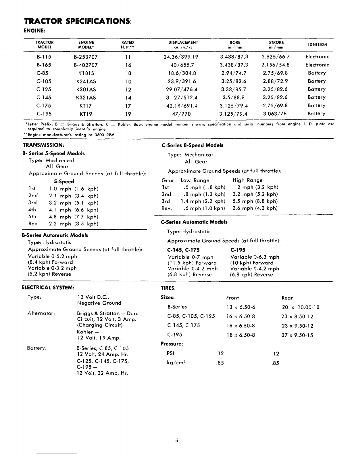
TRACTOR SPECIFICATIONS:
ENGINE:
TRACTOR
MODEL
B-115
B-165
C-85
C-I05
C-125
C-145
C-175
C-195
'Letter
Prefix: B = Briggs &
required
'*Engine
to
completely
manufacturer's
TRANSMISSION:
B-
Series
5-Speed
Type:
Mechanical
All
Gear
Approximate
5-Speed
1
st
2nd
3rd
4th
5th
1.0
2.1
3.2
4.1
4.8
Rev. 2.2
Type:
Automatic
Hydrostatic
B-Series
Approximate
Variable
(8.4 kph)
Variable
0-5.2
Forward
0-3.2
(5.2 kph) Reverse
Models
Ground
mph
mph
mph
mph
mph
mph
Models
Ground
mph
mph
ENGINE
MODEL'
B-253707
B-402707
K181S
K241AS
K301AS
K321
AS
KTl7
KTl9
Stratton,
identify
engine.
rating
at
3600
Speeds
(1.6
kph)
(3.4 kph)
(5.1 kph)
(6.6 kph)
(7.7
kph)
(3.5 kph)
Speeds
RATED
H.
P."
1 1
16
8
10
12
14
17
19
K = Kohler. Bosic
RPM.
(at
full throttle):
(at
full throttle):
engine
DISPLACEMENT
cu.
in.;'
cc
24.36/399.19
40/655.7
18.6/304.8
23.9/391.6
29.07/476.4
31.27/512.4
42.18/691.4
47/770
model
number
C-Series
Type:
shown;
a-Speed
Mechanical
All
Approximate
Gear
1st .5
2nd
3rd
Rev. .6
C-Series
Type:
Low
Range
mph
.8
mph
1.4
mph
mph
Automatic
Hydrostatic
Approximate
C-145, C-175
Variable
0-7
(11.5 kph)
Variable
0-4.2
(6.8 kph) Reverse
3.125/79.4
specification
Models
Gear
Ground
( .8 kph) 2
(1.3 kph)
(2.2 kph)
(1.0 kph)
Models
Ground
mph
Forward
mph
BClRE
in./mm
3.438/87.3
3.438/87.3
2.94/74.7
3.25/82.6
3.38/85.7
3.5/88.9
3.125/79.4
Ilnd
serial
Speeds
High
(at
Range
mph
3:.2
mph
5.5
mph
2.6
mph
Speeds
(at
full throttle):
C··195
VClriable
(10 kph)
Vcuiable
(6.8 kph) Reverse
STROKE
in./mm
2.625/66.7
2.156/54.8
2.75/69.8
2.88/72.9
3.25/82.6
3.25/82.6
2.75/69.8
3.063/78
numbers
from
full throttle):
(3.2 kph)
(5.2 kph)
(8.8 kph)
(4.2 kph)
0-6.3
mph
Forward
0-4.2
mph
engine
IGNITION
Electronic
Electronic
Battery
Battery
Battery
Battery
Battery
Battery
I.
D.
plate
are
ELECTRICAL
Type:
Alternator:
SYSTEM:
12
Volt D.C.,
Negative
Briggs &
Ground
Stratton
Circuit, 12 Volt, 3
Battery:
(Charging
Kohler
12 Volt, 15
B-Series, C-85, C-105 -
12 Volt,
-
24
Circuit)
Amp.
Amp.
C-125, C-145, C-175,
C-195
-
12 Volt,
32
Amp.
- Dual
Amp.
Hr.
Hr.
TIRES:
Sizes:
B-Series
C-85, C-l
C-145, C-175
C-195
Pressure:
PSI
kg/cm
ii
05, C-125
2
Front
13
16 x 6.50-8
16
18 x
12
.85
x
6.50-6
)(
6.50-8
6.50-8
Rear
20 x 10.00-10
23 x
8.50-12
23 x 9.50-12
27x9.50-15
12
.85
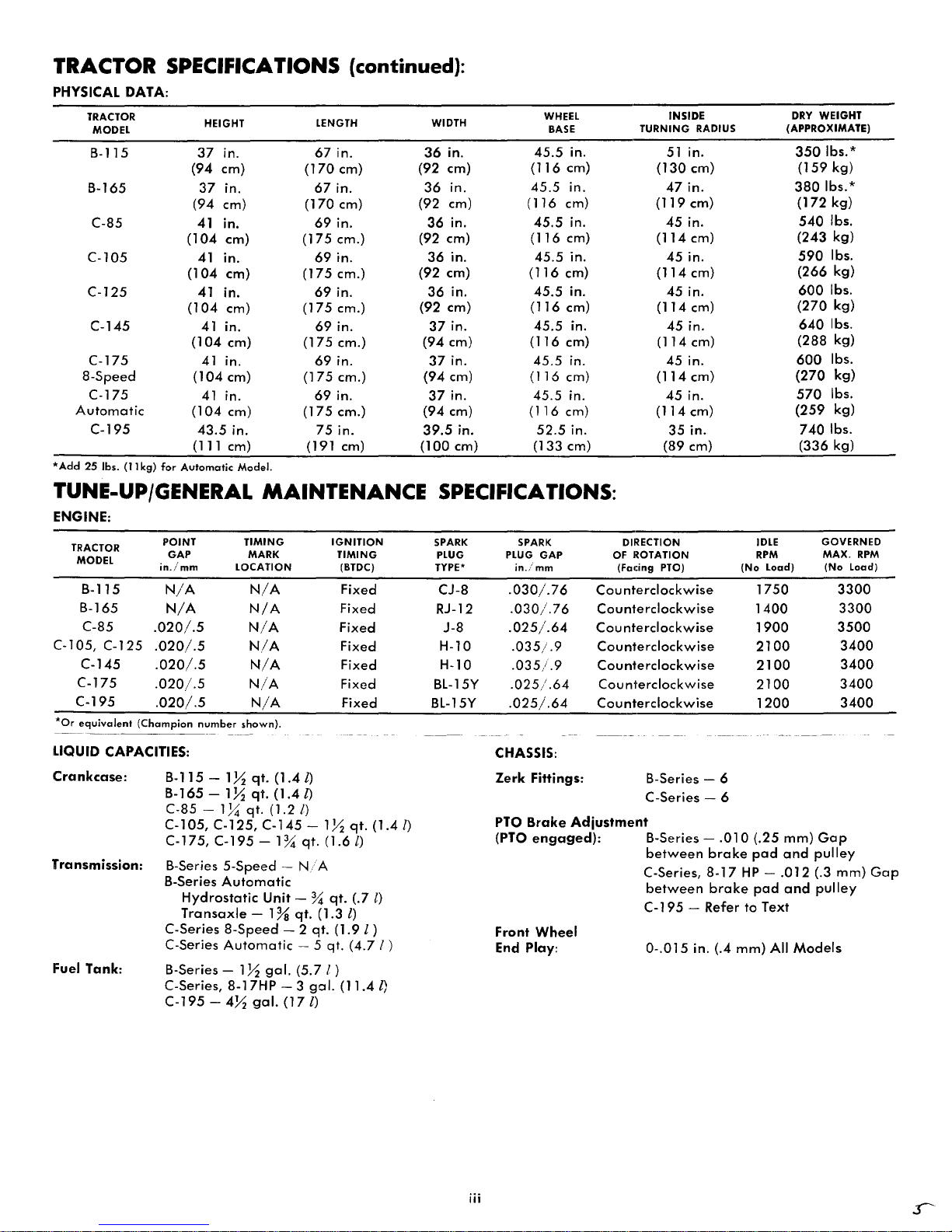
TRACTOR SPECIFICATIONS (continued):
PHYSICAL
Automatic
*Add
DATA:
TRACTOR
MODEL
B-115
B-165
C-85
C-l05
C-125
C-145
C-175
8-Speed
C-175
C-195
25
Ibs.
(11
kg)
for
HEIGHT
37
in.
(94 em)
37
in.
(94 em)
41
in.
(104
em) (175 em.)
41
in.
(104
em) (175 em.)
41
in.
(104
em) (175 em.)
41 in.
(104
em)
41
in.
(104
em)
41
in.
(104
em)
43.5
in.
(111 em)
Automatic
Model.
LENGTH WIDTH
67
(170
67
(170
69
in.
em)
in.
em)
in.
36
(92 em)
36
(92 em)
36
(92 em)
69
in.
36
(92 em)
69
in.
36
(92 em)
69
in.
(175 em.)
69
in.
(175
em.)
69
in.
(175
em.)
75
in.
(191 em)
37
(94
37
(94
37
(94 em)
39.5
(100 em) (133 em) (89 cm)
in.
in.
in.
in.
in.
in.
em)
in.
em)
in.
in.
WHEEL
BASE
45.5
in.
(116
em)
45.5
in.
(116 em)
45.5
in.
(116
em)
45.5
in.
(116
em)
45.5
in.
(116
em)
45.5
in.
(116
em)
45.5
in.
(116
cm)
45.5
in.
(116
cm)
52.5
in.
INSIDE
TURNING
51
(130
47
(119
45
(114
45
(114
45
(114
45
(114 em)
45
(114
45
(114
35
RADIUS
in.
em)
in.
em)
in.
em)
in.
em)
in.
em)
in.
in.
em)
in.
em)
in.
DRY
WEIGHT
(APPROXIMATE)
350
Ibs. *
(159
kg)
380
Ibs.*
(172
kg)
540
Ibs.
(243
kg)
590
Ibs.
(266
kg)
600
Ibs.
(270
kg)
640
Ibs.
(288
kg)
600
Ibs.
(270
kg)
570
Ibs.
(259
kg)
7401bs.
(336 kg)
TUNE-UP/GENERAL
ENGINE:
(Champion
--------
POINT
GAP
in./mm
N/A
N/A
.020/.5
.020/.5
.020/.5
.020/.5
.020/.5
B-115 - 1 X
TRACTOR
MODEL
B-115
B-165
C-85
C-l05,
C-125
C-145
C-175
C-195
*Or
equivalent
---
--~--
LIQUID
CAPACITIES:
Crankcase:
B-165 -
C-85 C-l05,
C-175, C-195
Transmission:
B-Series
B-Series
Hydrostatic
Transaxle
C-Series
C-Series
Fuel Tank: B-Series - 1 X
C-Series,
C-195 -4X
TIMING
LOCATION
number
shown).
IX
1~
C-125,
5-Speed -N/
Automatic
8-Speed
Automatic
8-17HP
MAINTENANCE
I)
- 1 X
qt.
(1.6l)
A
qt.
(1.3
qt.
- 5 qt.
(5.7 I )
gal.
IGNITION
TIMING
(BTDC)
Fixed
Fixed
Fixed
Fixed
Fixed
Fixed
Fixed
qt.
qt.
(.7 l)
I)
(1.9l)
(4.71
(11.4
(1.4
I)
MARK
N/A
N/A
N/A
N/A
N/A
N/A
N/A
qt.
(1.4
qt.
(1.41)
qt.
(1.2/)
C-145
-1%
Unit - %
- 1 %
gal.
gal.
- 2
- 3
(171)
SPECIFICATIONS:
mm)
and
and
Models
GOVERNED
MAX.
(No
Load)
3300
3300
3500
3400
3400
3400
3400
Gap
pulley
(.3
mm)
pulley
RPM
Gap
SPARK
PLUG
TYPE'
CJ-8
RJ-12
J-8
H-l0
H-l0
BL-15Y
BL-15Y
SPARK
PLUG
GAP
in./mm
.030/.76
.030/.76
.025/.64
.035/.9
.035/.9
.025/.64
.025/.64
DIRECTION IDLE
OF ROTATION
(Facing PTO)
Cou
nterclockwise
Counterclockwise
Cou
nterclockwise
Counterclockwise
Counterclockwise
Counterclockwise
Counterclockwise
(No
RPM
Load)
1750
1400
1900
2100
2100
2100
1200
CHASSIS:
Zerk
Fittings:
B-Series - 6
C-Series - 6
PTO
Brake
I)
(PTO
Front
)
End Play:
Adjustment
engaged):
Wheel
B-Series between
C-Series,
between
.010
brake
8-17
brake
C-195 - Refer
0-.015
in. (.4
(.25
pad
HP -.012
pad
to
Text
mm)
All
iii
1.
2.
3.
4.
5.
6.
7.
8.
9.
10.
11.
12.
13.
14.
15.
Know
the
READ
THE
Do
not
allow
adults
tion.
Do
not
a
safe
distance
Clear
work
up
and
Disengage
neutral
Disengage
gine
(motor)
Disengage
gine
(motor)
justments.
Disengage
ing
or
not
Take
all
hicle
unattended;
take-off,
tral,
setting
removing
Do
not
stop
or
downhill.
slopes;
be
when
Reduce
slopes
loss
changing
Stay
which
Use
equipment.
a.
b.
c.
d.
Watch
ways.
When
charge
anyone
never
ascended,
descending.
and
of
alert
may
care
Use
only
Limit
Do
not
Use
counterweight(s)
suggested
out
using
of
controls
OWNER'S
allow
children
to
operate
carry
passengers.
away.
area
thrown.
all
attachment
before
speed a nd
near
power
before
power
before
power
in
use.
possible
lowering
parking
key.
or
Mow
across
in
control.
directions
for
holes,
cause
when
approved
loads
turn
in
for
any
material
vehicle
attempting
start
back
sharp
to
sharply.
owner's
traffic
and
MANUAL.
to
it
of
objects
to
attachments
leaving
to
attachment(s)
making
to
attachments
precautions
such
attachments,
brake,
suddenly
up
and
the
face.
up
exercise
turns
Be
especially
on
slopes.
rocks
the
vehicle
pulling
drawbar
those
you
Use
or
when
attachments
toward
while
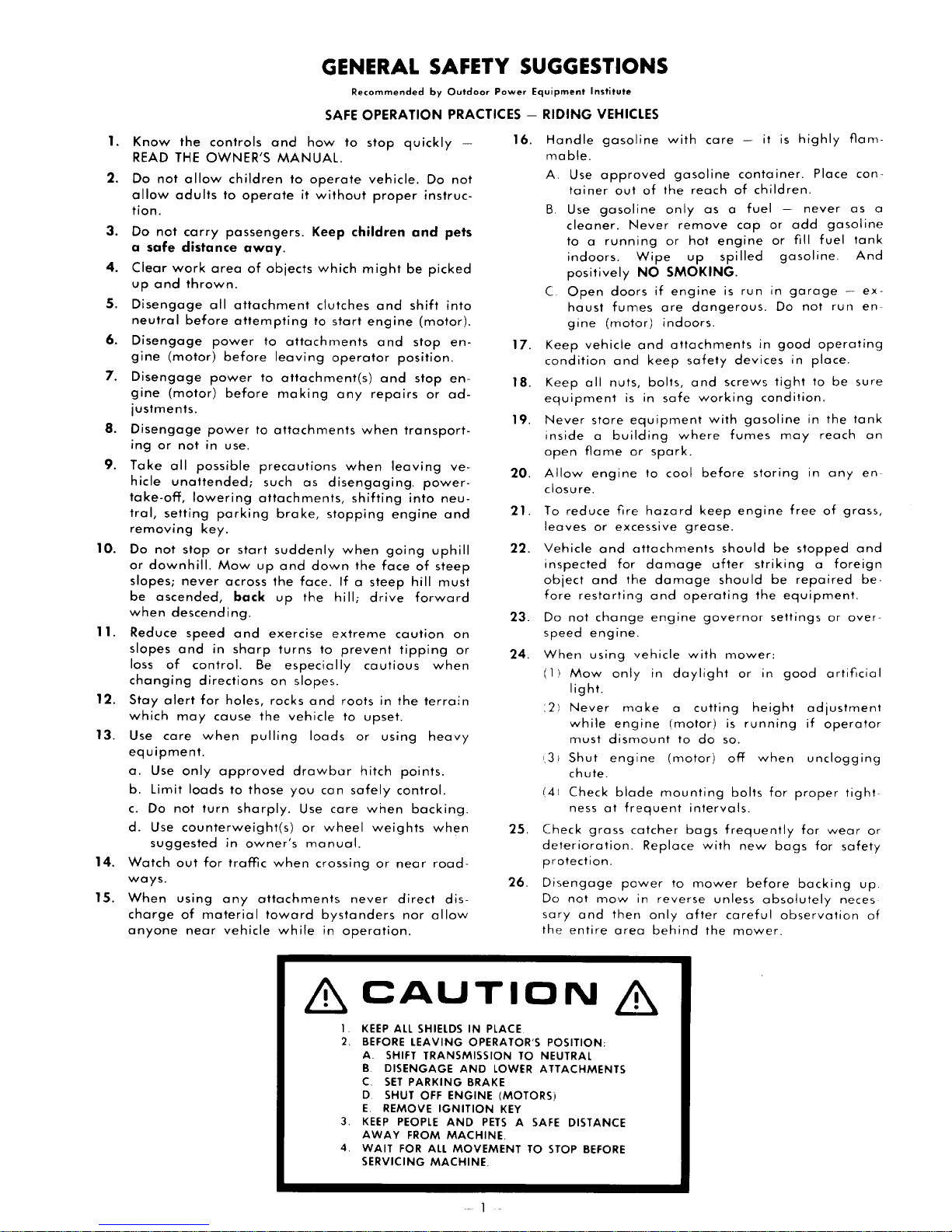
GENERAL SAFETY SUGGESTIONS
SAFE
how
operate
without
Keep
which
clutches
to
start
operator
any
as
disengaging.
stopping
when
down
If a steep
the
hill;
extreme
to
prevent
and
roots
to
loads
can
care
wheel
manual.
crossi
bystanders
in
operation.
Recommended
OPERATION
to
stop
vehicle.
proper
children
might
and
engine
and
and
repairs
when
when
shifting
the
face
drive
cautious
in
upset.
or
using
hitch
safely
when
weights
ng
or
never
by
quickly
Do
instruc-
and
be
picked
shift
(motor).
stop
position.
stop
or
transport-
leaving
power-
into
engine
going
of
hill
forward
caution
tipping
the
terrain
heavy
points.
control.
backing.
nea r road-
direct
nor
allow
Outdoor
PRACTICES -
-
not
pets
into
en-
en-
ad-
ve-
neu-
and
uphill
steep
must
on
or
when
when
dis-
Power
16.
17.
18.
19.
20.
21.
22.
23.
24.
25.
26.
Equipment
RIDING
1.31
(41
Check
deterioration.
protection.
Disengage
Do
sary
the
Institute
VEHICLES
Handle
mabie.
A Use
B.
C
Keep
condition
Keep
equipment
Never
inside a building
open
Allow
closure.
To
leaves
Vehicle
inspected
object
fore
Do
speed
When
(1)
:2)
gasolline
approved
tainer
out
Use
gasoline
cleaner.
to a running
indoors.
positively
Open
doors
haust
fumes
gine
(motor)
vehicle
and
all
nuts,
store
flame
engine
reduce
not
Mow
light.
Never
while
must
Shut
chute.
Check
ness
not
entire
fire
or
excessive
and
for
and
restartin';J
change
engine.
using
onl)!
moke
en9ine
dismount
engine
blade
at
grass
power
mow
and
then
area
with
gasoline
of
the
only
!'-Iever
is
or
the
frequent
remove
or
Wipe
NO
SMOKING.
if
engine
are
indoors.
and
attachments
keep
bolts,
in
safe
equipment
where
spark.
to
cool
hazard
Cltlachments
damage
damage
and
engine
vehicle
in
daylight
a
(motor)
to
(motor)
mounting
catcher
Replace
to
in
reverse
only
behind
care -it
reach
as a fuel
hot
engine
up
spilled
is
dangerous.
safety
and
screws
working
with
fumes
before
keep
grease.
should
ufter
should
operating
governar
with
mower:
cutting
IS
do
so.
off
bolts
intervals.
bags
frequently
with
mower
unless
after
careful
the
container.
of
children.
cap
ar
or
run
in
Do
in
devices
tight
condition.
gasoline
storing
engine
be
striking
be
the
settings
or
in
height
running
when
for
new
bags
before
absolutely
mower.
is
highly
add
fill
gasoline.
garage .-ex·
not
good
in
may
free
stopped
repaired
equipment.
gaod
proper
for
backing
observation
flam·
Place
never
gasoline
fuel
run
operating
place.
to
be
in
the
reach
in
any
of
grass,
a
foreign
or
over·
artificial
adjustment
if
operator
unclogging
tight
wear
for
safety
neces
con·
as
tank
And
en-
sure
tank
en-
and
be·
up
a
an
or
of
&CAUTION
1
KEEP
ALL
2.
3.
4.
BEFORE
A.
B.
C.
D
E.
KEEP
AWAY
WAIT
SHIELDS
LEAVING OPERATOR'S POSITION:
SHIFT
TRANSMISSION
DISENGAGE AND
SET
PARKING
SHUT
OFF ENGINE (MOTORS)
REMOVE
PEOPLE
FROM
FOR
ALL
SERVICING MACHINE.
IN
BRAKE
IGNITION
AND
PETS A SAFE
MACHINE.
MOVEMENT
PLACE.
LOWER
KEY
TO
NEUTRAL
ATTACHMENTS
DISTANCE
TO
STOP
&
BEFORE
VEHICLE
IDENTIFICATION NUMBER (VIN) LOCATIONS
Vehicle
major
your
dealer
may
require.
always
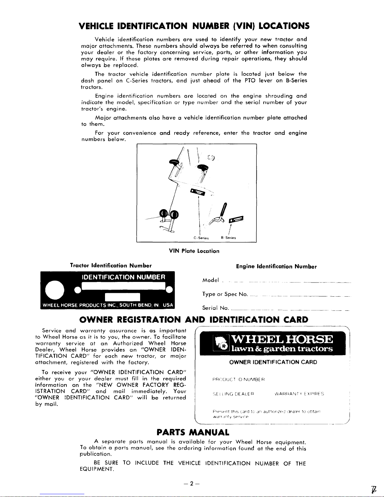
The
dash
panel
tractors.
Engine
indicate
tractor's
Major
to
them.
For
numbers
identification
attachments.
or
the
If
these
be
replaced.
tractor
on
C-Series
identification
the
model,
engine.
attachments
your
convenience
below.
These
factory
plates
vehicle
specification
also
numbers
numbers
concerning
are
removed
identification
tractors,
numbers
and
or
have a vehicle
and
ready
are
should
number
just
are
type
used
to
always
service,
during
ahead
located
number
identification
reference,
identify
be
parts,
repair
plate
of
on
and
enter
your
referred
or
other
operations,
is
located
the
PTO
the
engine
the
seriCiI
number
the
new
t,:>
when
information
just
lever
shrouding
number
plate
tractor
tractor
consulting
they
should
below
on
B-Series
of
attached
and
engine
and
you
the
and
your
Service
to
Wheel
warranty
Dealer,
TIFICATION
attachment,
To
either
information
ISTRATION
"OWNER
by
Horse
Wheel
receive
you
mail.
Tractor
Identification
Number
OWNER REGISTRATION
and
warranty
as
it
service
CARD"
registered
or
CARD"
IDENTIFICATION
your
on
at
Horse
"OWNER
your
the
is
to
an
provides
for
each
with
dealer
"NEW
and
assurance
you,
the
owner.
Authorized
an
new
tractor,
the
factory.
IDENTIFICATION
must
fill
OWNER
mail
immediately.
CARD"
will
is
Wheel
"OWNER
in
FACTORY
as
important
To
the
be
VIN
facilitate
Horse
IDEN-
or
major
CARD"
required
REGYour
returned
Plate
AND
Location
Model
Type
Serial
Engine
or
Spec
No.
___________________
No.
Identification
__
_
IDENTIFICATION CARD
lalWHEEL
~
lawn & garden
OWNER IDENTIFICATION CARD
PRODUCT
C,E
PfI-·'").·nt
Wdrr
I
liNG
,H~ty
10
DEALE
thl~
card
SPr-,/I('P
NU'V113E
R
te-
R
drl
autr")()rllf"U
Number
_
HORSE
tractors
dpdlpr
tu
tJt)talfl
)
A
separate
To
obtain a parts
publication.
BE
SURE
EQUIPMENT.
TO INCLUDE
parts
manual,
PARTS
manual
see
the
THE
MANUAL
is
available
ordering
VEHICLE
-2-
for
your
Wheel
information
IDENTIFICATION
found
Horse
NUMBER OF THE
at
equipment.
the
end
of
this

INSTRUMENTS
AND
CONTROLS
B-SERIES
TRACTORS
S-SPEED
2
/
/
~
5
MODELS
10
AUTOMATIC
-3-
MODELS

1. THROnLE CONTROL
The
the
Raise
to
start
2.
The
dash
tien
after
been
start
throttle
dash
the
the
CHOKE
choke
panel.
when
the
running,
it.
panel.
lever
engine.
control
Raise
starting
engine
control
to
is
This
operate
CONTROL
is
located
the
choke
the
engine.
starts.
choking
If
3. IGNITION SWITCH
The
ignition
the
dash
tion
switch
(1) Off, (2) Run, (3)
key
all
the
the
engine
the
Run
engine
off.
the
brake
and
engage,
therefore,
pesition
seat
switch
seat,
and
brake
back
brake
foot
and
foot
6.
tractor.
Note:
clutch
transmission
7.
tractor.
things:
necting
ates a safety
operate.
stops
4.
PTO
The
PTa
tractor,
pedal.
disengaged
To
engage
pull
The
PTa
before
is
vacated
will
5.
PARKING
The
parking
to
to
the
ToO
engage
solidly
(Automatic)
On.
To
release
brake.
will
brake
BRAKE
The
brake
Pushing
When
pedal
CLUTCH
The clutch
Pushing
(1)
the
Engaging
switch
panel,
has
way
starts
position.
and
above
three
Start.
to
the
and
When
all
is
it will
electrical
(POWER TAKE-OFF)
clutch
lever
is
between
Power
the
the
lever
the
autematically
the
driven
with
the
PTa,
lever
back.
actuates a safety
PTa
lever
the
engine
while
the
BRAKE
brake
the
right
left
on
the
and
the
The
return
is
applied.
PEDAL
pedal
coming
as
will
PEDAL
pedal
Declutches
engine
interleck
lever
on
manual
automatic
parking
then
move
or
forward
parking
parking
toO
the
disengaged
(5-Speed Models)
is
lecated
down
en
to a stop
well
as
be
disconnected
(5-Speed Models)
is
located
down
on
the
frem
the
clutch
located
lever
controls
the
lever
the
engine
may
net
located
the
throttle
positions
To
start
right.
automatically
the
switch
located
parking
attachments
PTa
push
lever
must
will
PTa
shut
LEVER
is
lecated
transmissien
brake,
the
brake,
brake
at
the
pedal
the
brake
at
the
clutch
tractor
the
transmission;
switch,
is
on
the
tractor;
on
Siewly
Release
accessories
the
to
be
en
control.
from
the
is
lower
left
lower
is
necessary
the
engine,
turned
CLUTCH
on
the
brake
lever.
forward.
interlock
be
in
the
start.
If
is
engaged,
off
the
engine.
in
transmission
first
apply
parking
(5-Speed)
push
lever
is
spring
pesition
the
right
applies
always
pedal
from
the
left
pedal
drive
so
the
doOne
by
right
engine
the
side
the
Cold
the
warm
right
The
left
to
the
key
return
are
LEVER
right
lever
are
engaged
disengaged
the
operator's
front
tractors,
tractors.
the
brake
toO
leck
dewn
when
side
the
depress
so
that
the
side
dees
belt,
(2) Actu-
starter
releasing
side
speed.
lever
of
the
posilever
and
has
toO
re-
side
igni-
right:
turn
the
when
off,
the
turned
side
and
the
To
dis-
switch;
a
seat
of
the
foot
lever
the
on
the
loaded
the
ef
the
brake.
the
the
engine.
of
the
two
discon-
will
the
of
of
to
of
pedal
the
depress
or
pedal
out
which
slowly
the
of
gear
tightens
pedal
and
the
when
when
when
8. BRAKE/RETURN
(Automatic Models)
The
brake
tractor,
through
pedal
is
tral.
When
mechanical
ing
action.
the
engine,
switch,
9.
GEAR
The
gear
seat.
Select
the
lever
tern
decal.
pedal,
provides
the
automatic
depressed,
the
brake
The
as
allowing
SHIFT
shift
any
to
the
dynamic
the
brake
is
pedal
the
the
lever
forward
pesition
located
transmission
also
must
pedal
starter
LEVER
is
10. MOTION CONTROL
(Automatic Models)
The
motion
steering
meved
right
and
control
control
independent
speed,
power
left
and
pull
lever
move
by
wheel.
and
ahead
back
lever
moving
contrcil
right
to
to
varies
of
lever
The,
in
to
go
reverse.
neutral
ground
engine
away
lever
lever
motion
the
11. TRANSMISSION
(Automatic Models)
The
transmission
of
the
seat
disconnects
the
lever
down
missien.
transmission.
Always
starting
12.
The
steering
the
attachments
tachments
13.
The
dash
toggle
eff.
ning.
14.
The
the
epen,
necessary.
Push
the
LIFT
manual
wheel.
lever
LIGHT
light
panel,
to
turn
The lights will
FUEL
fuel
fuel
tank.
except
to
the
disengage
engine
LEVER
ferward
used
before
switch
above
shut-off
when
clutch
the
right.
engiine
and
to
the
the
lever
the
in cold
lift
lever
Depress
or
with
lelJving
SWITCH
is.
located
the
choke
lights
on.
work
SHUT-OFF
valve
The
fuel
se·rvice
backward
the
Lower
shut-eff
drive
belt.
Always
engaging
shifting
starting
TO
braking
transmission.
pedal
appled
be
actuates a safety
the
the
transmission
the
NEUTRAL
at
the
to
beth
is
is
fully
for
additional
depressed
to
operate.
clutch.
engine.
PEDAL
left
side
rear
As
shifted
depressed,
when
the
(5-Speed Models)
lecated
speed
indicated
or
just in
reverse
en
the
front
by
shift
LEVER
is
located
control
neutral
ferward.
The
brake
fer
dynamic
speed
speed.
from
neutral.
toward
CLUTCH
lever
is
The
tra
from
the
left
to
to
the
transmission
weather.
is
lecated
the
release
tractor.
the
tracter
on
contrel.
the
enly
while
nsmission
just
lever
slot.
Push
Move
the
pedal
braking.
and
pulling
To
increase
Increase
neutral.
LEVER
located
transmission.
disconnect
right
to
clutch
just left
button
to
lower
Always
unattended.
the
left
Raise
teggle
toO
the
engine
below
lever
moves
just
clutch
the
engage
and
lower
side
the
turn
VALVE (Not Shown)
is
located
on
the
valve
fuel
at
the
is
system
bettem
normally
becomes
release
Always
into
of
the
wheels
brake
toO
neu-
brak-
starting
interlock
ef
the
meving
pat-
the
may
the
lever
left
the
The
power
ground
pulling
in
frent
lever
Push
trans-
the
when
of
the
move
er
raise
at-
ef
the
switch
lights
is
run-
of
left
a
be
-4-

INSTRUMENTS
AND
CONTROLS
8-SPEED
C-SERIES
16
MODELS
16
TRACTORS
1.
AMMETER
The
ammeter
the
right
of
7
gauge
ing
4
charged
2. THROnLE
The
the
dash
the
lever
to
start
3.
CHOKE
The
dash
panel.
when
starting
the
engine
running,
the
indicating
(+)
throttle
panel.
fully
the
engine
choke
control
Raise
starts.
choking
is
located
steering
the
rate
or
discharged
CONTROL
control
This
lever
to
operate
..
CONTROL
is
the
choke
the
engine.
Ii:
the
may
on
column.
at
is
located
controls
the
located
Slowly
engine
not
be
the
which
(-).
on
tractor;
on
lever
lower
is
warm
necessary
dash
The
the
the
engine
lower
the
left
to
the
panel,
ammeter
battery
right
speed.
the
side
Cold
the
lever
and
has
to
restart
just to
is
is
be-
side
of
Raise
lever
of
the
position
after
been
it.
a
C-195 AUTOMATIC MODEL
16
C-145, C-175 AUTOMATIC MODELS
10
4.
BRAKE
The
brake
tractor.
Note:
clutch
transmission
tractor.
things:
necting
a
Engaging
which
pedal
depress
or
Pushing
When
pedal
5.
CLUTCH
The
cI
Pushing
(1)
the
safety
tightens
slowly
the
out
of
6.
BRAKE/RETURN
pedal
coming
as
will
utch
peda I is
Declutches
engine
interlock
the
pedal
gear
PEDAL
clutc:h
(Automatic Models)
The
brake
tractor,
through
pedal
is
tral.
When
mechanical
ing
action.
the
engine,
interlock
pedal,
provides
the
automatic
depressed,
the
brake
The
as
switch,
is
down
well
be
PEDAL
down
from
switch,
thEl
when
when
and
when
d)rnamic
the
brake
is
pedal
the
allowing
(S-Speed Models)
located
on
to a stop
as
disconnected
the
the
at
pedal
brake
the
applies
always
pedal
from
(S-Speed Models)
located
on
the
is
done
drive
engaging
located
transmission
also
must
pedal
at
the
the
clutch
tractor
the
so
belt.
shifting
starting
TO
braking
transmission.
pedal
applied
be
linkage
the
drive
transmission;
the
starter
by
releasing
Always
the
the
NEUTRAL
at
the
to
is
fully
for
depressed
starter
the
actuates a safety
right
side
the
depress
so
that
the
engine.
left
side
pedal
does
belt,
discon-
(2)
Actuates
will
operate.
the
release
clutch.
transmission
engine.
Always
PEDAL
left
side
both
rear
As
is
shifted
additional
when
to
wheels
the
to
depressed,
starting
operate.
of
the
brake.
the
the
of
the
two
pedal
the
into
of
the
brake
neu-
brak-
a
-5-

7.
PTO
(POWER
The
PTO clutch
the
tractor.
and
disengaged
forward
back
lever
circuit;
lever
seat
switch
S.
The
seat.
moving
shift
9.
The
just
or
position
range
pulling
three
mid-point
with
to
to
disengage
actuates a safety
therefore,
is in
the
is
vacated
will
GEAR
gear
Select
any
the
pattern
RANGE
range
forward
low
range
indicated
provides
power
forward
position
the
gear
10. MOTION
lever
Power
engage
automatically
driven
with
the
disengaged
while
SHIFT
shift
lever
of
three
lever
to
decal.
SELECTOR
selector
of
the
gear
by
moving
on
a 4
for
moving
speeds
for
shift
lever.
CONTROL
(Automatic Models)
The
steering
tractor
the
brake
tion
ground
pendent
move
by
is
ceptible
neutral.
motion
forward.
lever
pedal
for
lever
moving
provided
11. PARKING
The
To
To
parking
to
the
engage
solidly
to
release
brake.
return
is
seat
brake
back
foot
will
brake
control
wheel.
to
the
moves
dynamic
speed
and
of
engine
away
lever
with a detent
feel'
as
brake
left.
the
and
lock
the
the
The
to
the
applied.
Push
Pull
neutral
braking.
pulling
speed.
from
toward
the
BRAKE
parking
then
brake
parking
parking
disengaged
12. TRANSMISSION
(Automatic Models)
The
the
seat
clutch
transmission
and
the
lever
disconnects
clutch
motion
TAKE-OFF)
is
located
attachments
the
PTO
the
attachment.
the
attachment.
interlock
tractor
position.
the
PTO
shut
LEVER
(S-Speed Models)
is
located
forward
the
position
(S-Speed Models)
is
located
shift
the
the
range
to 1 speed
heavy
and
neutral;
lever
is
the
lever
the
lever
(center)
the
lever
The
power
To
neutral.
neutral.
type
control
LEVER
lever
is
brake,
move
On.
brake,
lever
CLUTCH
lever
control
the
engine
on
lever.
switch
will
not
is
off
just
speeds
in
lever.
lever
selector
reduction
loads
reverse.
neutral
LEVER
located
ahead
back
position
to
control
of
increase
Increase
The
stop
lever
located
first
the
parking
push
is
spring
position
is
lever.
CLUTCH
the
right
are
Push
Pull
The
in
start
If
the
engaged,
the
engine.
in
front
or
indicated
front
of
Select
either
right
or
decal.
and
in
each
Do
not
must
just
right
to
for
reverse.
to
the
neutral
lever
the
tractor
ground
pulling
neutral
to
give a 'per-
passes
in
front
apply
brake
down
loaded
when
LEVER
located
The
transmission
from
LEVER
side
engaged
the
lever
the
lever
PTO
clutch
the
starter
unless
operator's
a
of
reverse
on
the
seat,
high
left
to
greater
of
use
be
selected
of
drive
Move
stop.
posi-
varies
inde-
speed,
power
position
through
of
the
foot
lever
on
and
the
foot
between
the
trans-
of
this
seat
the
by
the
the
low
the
a
the
the
The
the
the
mIssIon. Pull
connect
Push
transmission.
Always
the
engine
the
the
transmission.
the
lever
disengage
in cold
13. MANUAL
The
manual
steering
the
attachments
to
ground,
be
knob
desired
leaving
14.
just
and
on
Pull
to
to
an
down.
tractor
trolling
lower
a
II
This
and
15.
dash
to
work
position.
wheel.
lever
hold
an
the
limited
right
position.
the
HYDRAULIC
On
C-195
below
C-175
the
lower
the
lever
hold
attachment
lower
attachment
Always
unattended.
The
C-195
the
optration
the
way
permits a rear
down
LIGHT
The
light
panel,
turn
on
only
lift Ilever
Depress
forward
used
attachment
forward
by
the
or
left
tractor
models,
the
left
models
dash
back
attachment.
at
lower
is
also
optional
described
forward
freely
SWITCH
switch
just
above
lights.
when
16. IGNITION
The
ignition
the
dash
ignition
(1) Off, (2) Run, (3)
key
engine
Run
engine
off.
17.
column
ating
lS.
the
open,
comes
switch
all
the
starts
position.
stops
HOUR
The
hour
and
time
FUEL
The fuel
fuel
tank.
except
necessary.
switch
panel,
has
way
to
and
When
and
METER
meter
is a convenient
between
SHUT-OFF
shut-off
The
when
lever
up
forward
the
transmission
weather.
LIFT
(S-Speed Models)
is
the
lor
backward
with
the
at a certain
(down)
Dial-A-Hite
until
the
AI:ways
unattended.
LIFT
the
hydraulic
front
corner
the
hydraulic
panel,
to
lift
in
position.
The
any
position
attachments
equipped
3-point
above,
it will lock in a
mounted
during
lower
is
the
use.
located
the
toggle
ignition
SWITCH
is
located
just
above
three
positions
Start.
To
the
right.
it will
all
automatically
the
switch
electrical
(C·195 Only)
is
located
maintenance
VALVE (Not Shown)
valve
is
fuel
shut-off
service
and
to
the
rear
to
and
down
to
engage
when
starting
located
release
tractor.
travel
selector.
lift
lower
just
button
to
lower
When
it is
height
of
the
Turn
lever
is
attachments
left
and
or
desired
above
lever
the
held
(Automatic Models)
lift
lever
is
located
of
the
seat.
On
lift
lever
is
located
below
attachment.
neutral
choke
start
Release
to
located
the
Push
position
from
before
with a lever
hitch.
if
the
attachment
on
the
control.
to
turn
switch
on
the
the
throttle
from
the
the
is
accessorie<;
the
left
way
to
periods.
at
valve
on
the
choke
Release
lever
will
full
up
leaving
Beside
lever
is
"float"
to
left
side
Raise
lights
off.
is
in
right
control.
left
engine,
key
when
return
turned
are
of
the
determine
the
bottom
is
normally
fuel
system
control.
forward
to
for
the
pushed
posision.
move
the
side
to
turn
off,
turned
steering
dis-
the
of
the
move
raise
the
can
hand
in
the
before
C-145
lever
hold
full
the
con-
lift/
up
of
the
toggle
lights
Run
of
The
right:
the
the
to
the
the
oper-
of
left
be-
-6-
I(

OPERATING YOUR TRACTOR
SAFETY INTERLOCK SYSTEM
The
safety
switches,
The
left
will
and
not
The
switch
seat
two
foot
not
the
start
tractor
shuts
while
for
pedal
start,
left
unless
CORRECT
Before
with
all
thoroughly.
before
oil
level
starting.
safe
starting
and
check
foot
is
also
off
the
PTO
interlock
starting.
the
that
pedal
both
equipped
the
switches
PTO clutch
the
is
switches
engine
is
engaged.
system
are
control.
PTO
clutch
depressed.
are
with a seat
if
the
driver
properly
ENGINE OPERATION
&
CAUTION
starting
controls.
starting.
(automatic
Always
Always
the
engine,
Read
this
check
transmission
the
check
become
owner's
engine
the
incorporates
actuated
If
is
disengaged,
The
engine
switch.
rises
&
transmission
models)
by
the
tractor
actuated.
off
familiar
manual
oil
level
before
two
the
will
This
the
Once
the
control
at
choke
reaches
be
up
"Correct
placing
low
should
When
sure
the
to
speeds,
normal
starting
to
engine
Automatic:
the
STARTING
engine
its
follow
tractor
normal
be
and
THE
has
started,
or
hesitates
applied
operating
IIhe
the
special
the
transmission
Transmission
into
ENGINE
position.
during
as
necessary
temperature.
engine
procedures
operation.
slowly
If
the
during
as
Operation",
Mechanical Transmission Models
Because
new
is
depressed
To
disengage
about
choke
Wheel
start
half
control
of
a buiilt·in
Horse will
and
the
the
engine
the
PTO.
way
to
all
the
not
PTO
depress
Move
the
way
safety
start
is
disengaged.
the
Operate
to
the
interlock
until
the
clutch
throttle
position.
Cold position.
return
the
engine
acceleration,
until
the
engine
cold
weather,
for
warming
described
before
system,
the
clutch
pedal
control
Move
choke
stalls
the
under
your
pedal
and
lever
the
Care
haust
gases
gas
which
monoxide
unconsciousness
Do
not
as a closed
STARTING
Automatic
Because
new
Wheel
is
depressed
To
start
disengage
about
choke
engages.
The
Run
half
control
Turn
switch
position
If
of
continuous
Off
position
for
one
consult
the
When
the
minute.
the
WARNING &
should
as
is
is a
run
garage.
THE
be
taken
they
colorless
dangerous
and
the
engine
ENGINE
to
contain
and
is
potentially
in
gas
confined
Transmission Models
of a built·in
Horse will not
and
the
engine
the
PTO.
way
to
all
the
ignition
the
is
spring
automatically.
engine
and
Troubleshooting
safety
the
PTO
depress
Move
the
Operate
way
key
engine
loaded
fails
to
cranking,
allow
Check
for
interlock
start
is
disengaged.
the
the
to
the
clockwise
starts,
and
start
turn
the
starter
cause
Checklist.
avoid
carbon
odorless.
that
until
the
brake
throttle
position.
Cold
until
release
will
after
the
motor
of
hard
inhaling
monoxide
can
lethal.
areas
system,
brake
pedal
control
Start
the
return
10
seconds
key
starting;
ex·
Carbon
cause
such
pedal
lever
Move
position.
starter
the
to
to
the
to
cool
your
and
the
key.
the
Always
in
the
start
the
Turn
the
engages.
switch
The
Run
position
If
the
of
continuous
Off
position
cool
for
starting;
Once
the
control
low
should
reaches
to
speeds,
be
normal
STOPPING
To
stop
Idle
position
position.
the
time
to cool
If
engine
before
the
&CAUTION
place
the
neutral
engine.
ignition
When
its
the
the
is
sprin9
automl::ltically.
engine
cranking,
anell
one
minute.
consult
engine
or
applied
is
engine
normal
hesitcltes
operating
THE
ENGINE
engine,
and
the
engine
hot, cdlow
turning
has
tlJrn
before
transmission
position
key
clockwise
engine
loaded
fails
to
start
allow
Check
the
Troubleshooting
started,
position.
during
as
necessary
temperature.
return
the
has
the
Ilhe
key
off. This
stopping.
&
gear
before
starts,
and
turn
the
the
ignition
been
attempting
until
release
will
after
the
starter
for
cause
slowly
If
the
acceleration,
until
throttle
working
engine
practice
shift
the
return
10
seconds
key
to
motor
of
Checklist.
return
the
engine
the
the
lever
key
to
hard,
to
idle a short
lever
starter
the
to
the
hard
choke
stalls
choke
engine
to
the
will
to
key.
the
to
at
the
Off
or
help
-7-

Note:
stopped
brake
if
don't
opportunity
In
by
Always
when
for
just a
give
THROTTLE
The
engine
This control
speed
designed
mum
the
and
Always
set
throttle
as
measured
of
the
The
engine
with a special
RPM.
engine
protects
operate
at % to
The
engine
of % throttle
Using
the
at
less
than % throttle
transmission
well
as
models.
case
of
turning
the
&CAUTION
remove
leaving
few
children
to
operate
CONTROL
control
should
Unlike
to
poor
tractor.
in
operate
it
from
the
full
speed.
MUST
tractor
damage
overall
not
your
an
damage
whenever
emergency,
ignition
the
the
minutes.
or
regulates
in
RPM
be
new
automobile,
most efficiently
tractor
be
while
tractor
key
key
and
tractor
unauthorized
this
machine.
(Revolutions Per Minute).
used
to
Wheel
governor
caused
with
operating
the
the
engine
may
on
automatic
performance
the
engine
to
the
&
set
the
unattended,
Prevent
persons
the
speed
regulate
Horse
that
this
governor
at a set
by
excessive
the
throttle
at a minimum
tractor
is
result
in
models,
may
Off
position.
parking
even
accidents,
an
of
the
ground
has
been
limits
maxiallows
speed,
RPM.
control
is in use.
operating
extensive
as
on
all
be
the
For
convenience
of
fuel
spills, it is
plastic
with
When
with a good
gasoline.
tractors
unleaded
engines.
lines.
fuel is
manufacturers.
In
buildup
tributes
Briggs
regular
operation,
leaded
OIL
To
oil level
cerning
level
tion of this
funnel
under-seat
the
Use
with Briggs &
regular
Do
Do
not
not
recommended
general,
of
combustion
to long
&
Stratton
gasoline
while
fuel
SPECIFICATION
protect
before
recommended
is
given
manual.
be
used
fuel
tractor
grade
not
mix
the
thereafter.
your
requires
(85
only
leaded
may
intermix
oil
with
use of
valve
en!~ines,
be
used
the
piston rings
new
each
in
the
"Maintaining
and
to
minimize
recommended
when
refueling
tanks.
refueling,
octane
Stratton
be
regular
gasoline.
unleaded
deposits
life. Except for
Wheel
use.
oils
minimum)
or
low-lead
used
in
by
either
in
it is
suggested
for
the
are
Horse, check
Complete
and
how
engines.
and
the
the
chance
that a large
tractors
fill
the
of
regular
regular
Leaded
tractors
The use
fuel will
with
Kohler
unleaded
of
these
engine
tractors
first 25
seating,
information
to check
Your Tractor" sec-
of
gasohol
reduce
and
that
hours
and
the
gaso-
engine
leaded
engine
the
tank
in
or
the
conwith
of
un-
con-
oil
CHOKE
the
pletely
results
easier
engines
FUEL
CONTROL
The
choke
carburetor.
closed, less
in a higher
to
ignite
may
A
special
cylinder
instructions
for
winter
The
the
chance
is
operated
weather.
In
the
directly
tion
heated
the
muffler.
Place
at
the
start
Summer
SPECIFICATION
Handle
mable.
add
fuel
tank
outdoors
tank
indoors.
wipe
up
control
not
activates a "butterfly"
When
when
the
air
is
fuel-to-air
the
need
WINTER
TWIN
tractors. A decal
purpose
Summer
into
the
position
air
on
use.
of
of
carburetor
in
the
outside
air
of
the
CYLINDER
intake
how
this
near-freezing,
position
air
cleaner.
air
intake
snow
in
the
&CAUTION
fuel
with
Use
only
approved
while
the
engine
with
extreme
Replace
all
spilled
fuel.
choke
admitted
engine
choking.
is
to
(richer)
is
started
OPERATION,
MODELS
system
to
set
system
is
in
season.
Spring.
care
gasoline
on
up
icing
outside
In
drawn
the
- it is
fuel
is
care.
is
the
is
to
when
the
in
Winter
Return it
container.
running.
cap
partially
the
engine.
mixture
cold.
used
engine
the
air
help
the
high
humidity
air
is
Winter
from
&
highly
Never
securely
valve
or
com-
that
Warm
on
twin
gives
intake
prevent
tractor
drawn
posi-
around
position
to
the
flam-
Never
Fill
fuel
fill
fuel
and
in
This
is
TRANSMISSION OPERATION
During cold
parking
clutch
least
two
up;
engage
engine
o
and
mission
attempting
peratures
mission
attempting
do
so
mission
TO
GO
Before
or
backward,
engaged.
neutral
brake.
The motion
single
"Motion
push
the lever forwclrd. The
is
pushed,
CORRECT
AUTOMATIC
weather,
brake
lever
at
30°F
to
to
may
damage.
FORWARD
pedal
the
engaged
disengaged.
minutes
full
run
to
below
run
to
to
the
transmission
throttle.
(18C and
in
neutral
set
the
OaF
in
neutral
set
the
result
&CAUTION
the
tractor
thE!
ALWAYS
when
of
your
Control
faster
the
start
and
Run
allow
For
temperatures
_2
unit
(-18
for
unit
in
extensive
will
parking
depress
disengaging
tractor
lever".
farther
tractor
the
engine
the
transmission
the
engine
the
engine
clutch
C
e)
allow
for 5 minutes
into
motion.
n
e)
allow
10
in
motion.
to
with
the
the
minutes
Failure
internal
&
move
either
brake
must
the
brake/return
the
is
controlled
To
go
forward,
forward
will go.
with
the
for
at
warm-
the
between
trans-
before
For
tem-
trans-
before
to
trans-
forward
be
dis-
to
parking
by
simply
the
lever
a
-8-

For
control
By
adjusting
speed
of
ing
the
moving
tractor
much
mechanical
TO
motion
the
faster
speed
ing
TO
reverse
methods:
the
applies
hold
The
lever
action
mechanical
(at a very
neutral.
when
though
in
the
when
HAND
ground
the
GO
To
reverse
control
lever
the
For
control
By
adjusting
of
the
engine
STOP
Stopping
direction
1.
Return
position.
2.
Depress
Activating
motion
a
the
pedal
can
The
tractor
inside
Therefore,
the
B-Series
neutral
brake
stopped
PUSHING TRACTOR
Hand
can
cause
transmission.
&
CAUTION
safe
operation,
lever
too
rapidly,
the
motion
the
tractor
engine
the
same
transmission.
throttle
control
speed
as
can
shifting
BACKWARD
the
motion
lever
to
back.
The
tractor
will
&CAUTION
safe
operation,
lever
too
rapidly,
the
motion
the
tractor
the
the
the
control
mechanical
motion
must
be
broke.
slow
tractor
even
is
recommended
push
throttle
tractor
can
motion
the
brake
brake
control
be
moved
is
stopped
the
speed)
is
tractors
when
on
tractor
severe
can
lever
released
either
hydrostatic
C-Series
always
stopped
unlevel
never
especially
control
be
regulated
control.
lever
toward
and
increases
to a lower
of
the
the
neutral
farther
go
control.
be
brake.
the
damage
back
in
reverse.
never
especially
control
be
regulated
from
achieved
control
pedal.
pedal
to
its
lever
in
before
forward
by a "dynamic
tractors
when
depress
on
will
tend
brake
to
terrain.
only.
Do
&
move
the
on
lever,
without
For
heavy
neutral
pulling
tractor,
position,
the
&
move
either
automatically
neutral
The
transmission
the
avoid
to
the
on
lever,
without
the
by
lever
to
brake
the
neutral
the
motion
or
back.
are
transmission
the
unlevel
to
remain
is
released,
accidental
not
tow.
the
hydrostatic
motion
grades.
the
forward
adjustpulling,
reduces
gear
with
return
and
lever
motion
grades.
the
reverse
adjust-
forward
one
of
its
neutral
returns
position
pedal
position.
control
braking"
and
free
to
brake
terrain.
stationary
use
Towing
power
the
pull
is
the
two
and
will
roll
is
pedal
Al-
of
starts
a
or
a
in
CORRECT
MECHANICAL
TRANSMISSION
TO
GO
FORWARD OR
With
the
engine
and
the
brake
Series
Move
ward,
the
release
ed,
Only)
the
or
various
the
the
tractor
Always
starting
be
damaging
loss
of
gear
to
speeds.
clutch
the
operatol'
TO CHANGE
When a change
quired,
by
Series)
each
of
or
motion
in
selected
gear
TO
the
fully
always
depressing
Never
motion.
may
Change
this
It
is
"down"
any
should
result.
as
gear
manual.
not
The
gear.
gear
attempt
Severe
the
desired.
is
necessary
STOP
To
stop
the
brake
pedal.
before
When
stopping
clutch
pedal
ing
the
broke
cessive
transmission
pedal
NOT
brake
without
STOP
through
tractor
be
the
to
&CAUTION
running,
pedals.
either
shift
lever
reverse.
will
release
trador
peda
tel
the
control.
The
Release
begin
the
in
SPEEDS
in
ground
br.ing
both
the
to
internal
gear
shift
The
shown
&
THE
in
or
the
has
If
the
tractor
with a heavy
used.
tractC)r,
The clutch
brake
CAUTION
the
first,
then
without
lining
damage.
depressing
TRACTOR.
OPERATION
REVERSE
depress
Move
the
range
the
High
or
the
to
the
desired
gear
shift
the
brake
I.
As
the
clutch
to
move.
&
clutch
pedal
motion.
equipment
OR
the
clutch
shift
approximate
the
recommended
gears
sufficient
depress
pedal
tractor
the
the
wear,
Sudden
and
DIRECTION
speed
or
tractor
lever
to a complete
and
the
gears
with
transmission
or
range
ground
specifications
with
power
will
not
load
attached, a lower
the
cI
pedal
must
is
depressed.
&
always
brake
pedal.
clutch
may
or
extensive
Depressing
the
brake
utch
both
the
selector
low
speed
decal
pedal.
peda I is
slowly
starts
could
direction
broke
the
damage
selector
in
to
shift
the
tractor
to
move
pedal,
be
depressed
depress
Depress-
cause
internal
the
pedal
clutch
(C-
position.
for-
identifies
Slowly
releas-
when
can
cause
is
re-
halt
pedals.
unit
in
(C-
speed
for
the
front
"up"
move
out
out
in
then
the
ex-
clutch
WILL
in
a
C-Series
pushed
faster,
for a moment,
slower
S-Series
pushed
transmission
lever
pushed.
at
the
speed.
at
fully
automatic
slightly
rear
wheels
then
automatic
slow
clutch
forward;
less
reSUrT'e
speeds.
lever
the
transmission
than
walking
will lock.
pushing
transmission
To
do
and
move
tractor
will
If
this,
the
tractors
speed;
this
occurs,
the
tractor
tractors
disengage
motion
then
move
can
if
pushed
can
control
be
wait
at
be
the
when
a
-9-
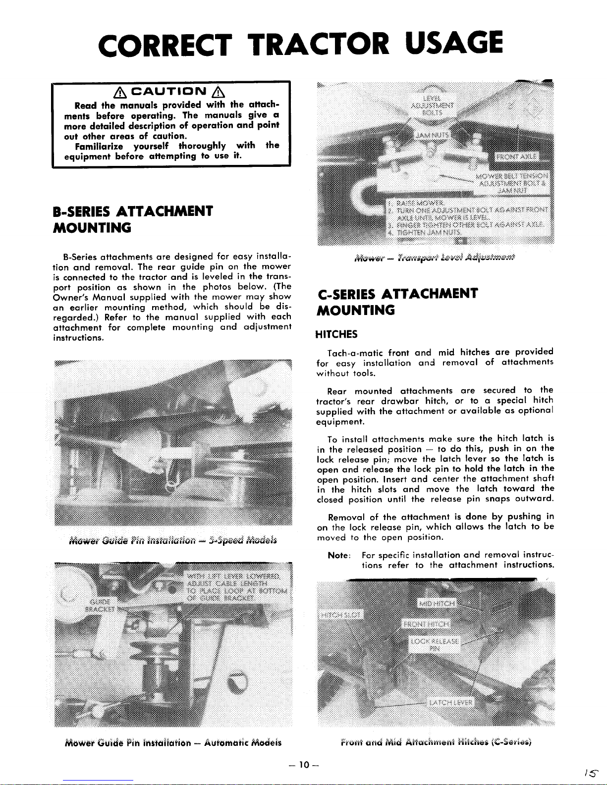
CORRECT TRACTOR USAGE
&CAUTION
Read
the
manuals provided
ments before operating. The manuals
more detailed description
out other areas
Familiarize yourself thoroughly
equipment
I-SERIES
of
before
ATTACHMENT
of
caution.
attempting to use it.
&
with
operation
MOUNTING
B-Series
tion
is
connected
port
Owner's
an
earlier
regarded.)
attachment
instructions.
and
removal.
position
Manual
attachments
The
to
the
tractor
as
shown
supplied
mounting
Refer to
for
complete
are
rear
method,
the
manual
designed
guide
and
is
in
the
with
the
which
mounting
pin
leveled
photos
mower
supplied
the aHach-
and
with
for
easy
on
the
in
below.
should
and
adjustment
give
point
installa-
the
may
be
with
a
the
mower
trans-
(The
show
dis-
each
C-SERIES
ATTACHMENT
MOUNTING
HITCHES
Tach-a-matic
for
easy
without
tools.
front
installation
and
and
mid
hitches
removal
are
of
attachments
provided
Rear
mounted
tractor's
supplied
equipment.
To
install
in
the
released
lock
release
open
and
open
position.
in
the
hitch slots cmd
closed
on
moved
position
Removal
the
lock
to
Note: For
rear
drawbar
with
the
attachments
pin;
release
Inser1'
of
the
release
the
open
specific
tions
attachments
hitch,
attachment
make
position -to
mc,ve
the
the
lock
pin
and
center
move
until
the
release
olttachment
pin,
which
position.
installation
refer
to
the
are
or
or
available
sure
do
this,
latch
lever
to
hold
the
the
pin
is
done
allows
and
attachment
secured
to a special
as
optional
the
hitch
push
in
so
the
the
latch
attachment
latch
toward
snaps
removal
outward.
by
pushing
the
latch
instructions.
to
the
hitch
latch
on
the
latch
in
the
shaft
the
to
be
instruc-
is
is
in
Mower
Guide hi'! liu:taliarioi'! - AUl'OMIll'ic:
Modei$
-10-
/s
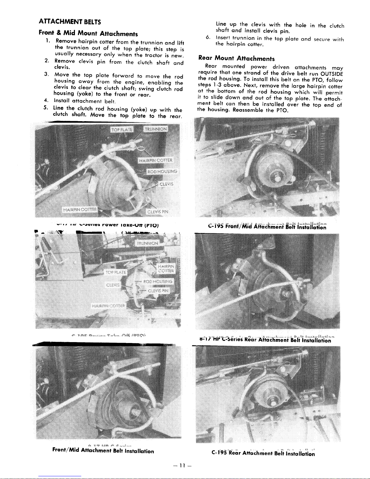
ATTACHMENT
BELTS
Front & Mid Mount
1.
Remove
the
usually
2.
Remove
clevis.
3.
Move
housing
clevis
housing
4. Install
5. Line
clutch
hairpin
trunnion
necessary
clevis
the
top
away
to
clear
(yoke)
attachment
the
clutch
shaft.
out
the
Move
Attachments
cotter
from
of
the
top
only
when
pin
from
the
plate
forward
from
the
engine,
clutch
to
rod
the
front
belt.
housing
the
shaft;
top
the
trunnion
plate;
the
clutch
to
swing
or
rear.
(yoke)
plate
this
tractor
shaft
move
enabling
clutch
up
with
to
the
and
step
is
the
lift
new.
and
rod
the
rod
the
rear.
line
up
shaft
and
install clevis pin.
6. Insert trunniion in
the
the· clevis
is
hairpin
Rear Mount
Rear
mounted
require
the
steps
at
it
ment
the
rod
1-3
the
to
slide
belt
housing.
that
housing.
above.
bottom
down
can
cotter.
Attachments
one
strand
T,:>
Next,
of
the
and
then
Reassemble
power
install
remove
rod
out
be
installed
with
the
of
the
this
housing
of
the
the
top
driven
drive
belt
the
the
top
PTO.
hole in
plate
and
attachments
belt
on
the
large
which
plate.
over
the
the
secure
run
OUTSIDE
PTO,
hairpin
will
The
top
clutch
with
may
follow
cotter
permit
attachend
of
11.-
"-~
..
ne:t
,.gwer
laKe-v"
(t'TO)
.....
~
IS';'I r,·fpvC;;-Series R.ear
.;..
..
,",
....... ; ..........
Attachment
~>
..
~>
~
.•.• ~ .......
:~
...
Belt Installation
~.;.;
••••.••
Front/Mid
Attachment
Belt Installation
-11-
OPERATION
Because
should
normal
addition
mize
available
of
be
encountered
conditions.
of
wheel
rear
tire
for
the
slippage. A rear
use
OF
power
On
rough,
weights
on
B-Series
THE
of
using
TRACTOR:
the
tractor,
these
attachments
hilly,
or
and
tire
chains
weight
tractors.
wet
no
problem
terrain,
will mini-
box
is
under
the
also
WITH A
The
front
Care
should
be
maintained
with
a solid
ator
and/or
Tire
chains,
may
be
SNOW
end
be
object
damage
added
BLADE
snow
taken
whenever
wheel
to
improve
(B-Series)
blade
and a slow
the
may
result
to
the
weights
rear
is
used
blade
in
blade.
and
for
ground
injury
the
tire
traction.
snow
is
rear
speed
used.
to
weight
removal.
should
Impact
the
oper-
box
WHEEL
ANY OTHER WEIGHT, SUCH AS
CHLORIDE, TO
EXTRA
SION
WITH A MOWER
HORSE
WEIGHT CAN CAUSE
DAMAGE.
DOES NOT RECOMMEND ADDING
THE
REAR
(All
Models)
TIRES.
WARNING
Keep
all
in
place.
or
mower
clutch
For
best
engine
speed
excessive
speed
Tall
in its
to
operated
mowing
usually
grass
highest
the
height
Always
with
Never
and
operation
at
full
the
at 2 to
grass.
ground
with
cut
at a height
and
keep
shields
blades
removing
throttle
the
weeds
position,
desired.
and
attempt
without
the
on
average
while
transmission.
3.5
MPH (3.2
Uneven
speed.
the
cutting
To
transmission.
between 2 and
should
making a second
mower
mower
to
ignition
correct,
blades
WITH A SNOWTHROWER
&CAUTION
Thoroughly
thrower
sleds,
make
ning.
engine
Snow
of
each
with
ease.
is
advisable
coat
of
wax
Best
results
ground
the
throw.er
up
pelling
charge
harm.
box
a
speed
Experience
wind.
Care
sticks,
them
chute
Tire
chains
on
B-Series
snowthrower.
boards
any
Never
is
removal
snowfall.
should
is
is
to
and
adjustments
try
running.
Heavy
to
coat
or
paraffin
are
is
set
will
be
engaged.
stones
with
away
and
tractors,
inspect
be
used.
other
to
will
vary
light
wet
the
usually
at 1 to
teach
exercised
The
and
great
from
wheel
the
area
Remove
foreign
while
clear
greatly
fluffy
snow
auger
to
keep
attained
2 MPH (1.6
you
auger
other
foreign
velocity.
persons
weights,
are
recommended
WATER
THIS
EXTENSIVE
discharge
clear
discharge
disengaging
key.
lawns,
controlling
The
tractor
to
5.6
is
often
reduce
Average
be
cut
with
sharp.
(All
Models)
&
where
all
objects.
the
engine
the
chute
with
snow
will
will
be
more
and
chute
snow
when
not
to
throw
whenever
is
capable
objects
Always
or
objects
plus
the
OR CALCIUM
ADDITIONAL
TRANSMIS-
chute
areas
the
PTO
operate
the
should
KPH)*
the
the
lawns
3 in. (5-7.6 cm).
the
pass
the
door
while
the
be
difficult.
with a light
from
the
to
3.2
snow
the
of
aim
subject
rear
when
the
ground
be
while
result
of
ground
are
mower
cutting
snow-
mats,
Never
is
run-
the
condition
cleared
sticking.
tractor
KPH).
into
snow-
picking
and
ex-
the
dis-
to
weight
using
*
It
WITH A
used
dirt,
ground
blade
in
Grader
sand,
similar
blades
dealer
tractor.
tor,
front
chains
traction.
WITH A
The
preparing
Caution
grou
push
the
trates
lowered
Rear
tire
Front
help
The
aggressive
usually
set
not
DOZER
Although
for
snow
sand
or
speed
is
used.
injury
to
the
blades
dirt
or
to
that
may
for
When
using
front
wheel
wheel
may
TILLER
Wheel
gardens
should
nd
or
clay
the
tractor.
tiller
with
only
the
to
its full
If
the
the
tiller
PTO clutch.
wheel
chains
at
Do
hold
will
weights
improve
slower
the
attained
less
than
not
over-till
water,
OR
the
front
removal,
gravel.
should
Impclct
oper'otor
ar,e
gravel.
of a dozer
require
the
proper
any
WE!ights
traction.
also
(All
Horse
as
the
very
depth
&
CAUTION
tiller
starts
off
immediately
weiglhts
reduce
may
steering
the
action
when
1.0
and
GRADER
end
it
can
Care
should
be
with a solid
and/or
generally
The
operation
special
hitch(es)
of
these
should
Rear
be
used
Models)
tiller
'for
planting.
be
exercised
the
ti
lIer
This
can
Clttachment lift
top
of
on
to
and
the
be
used
control.
tractor's
of
the
MPH
(1.6 KPH).*
the
soil. Soil tilled
will
compact
WITH A PLOW, DISC, CULTIVATOR,
OR
HARROW (C-Series)
Plows
and
disc
Cleat
tires,
increase
to
the
steering
Some
hitches.
required
• A verage
or
rear
of
these
Consult
for
your
walking
require
tire
tire
traction.
control
olttachments
your
tr.:lctor.
(:hains,
of
dealer
speed
maximum
the
BLADE
dozer
also
be
be
maintained
damage
preferred
blade.
does
pushing
the
as
Front
is
Rear
rear
hitches;
attachments
be
wheel
to
increase
an
when
may
have a tendency
be
corrected
the
soil. The tiller
following
push
the
by
disengaging
cleat
on
C-Series
ground
tiller. Best
tractor
well
wheel
tractor.
require
for
the
2.5
MPH
(C-Series)
blade
used
taken
whenever
object
to
of
these
mount
required
with
used
weights
excellent
tilling
so
the
passes.
&
tractor,
tires
(C-Series)
effect
speed,
ground
excessively
easily.
tractor
as
wheel
weights
special
proper
(4
is
generally
for
moving
and a slow
may
result
the
blade.
for
leveling
blades
grader
consult
rear
of
your
for
your
the
trac-
to
increase
and
wheel
job
virgin
by
raising
tiller
pene-
can
shut
the
the
tiller.
tractors
the
more
results
KPH).
are
speed
will
efficiency.
weights
add
rear
hitch(es)
the
is
tire
of
to
be
or
to
is
-
12-
17
There
are
for
planting.
1.
Use a tiller,
operation.
2.
Use a
up
large
smooth
Plows
are
will
turn.
Generally,
(10-15.2 cm)
A
disc
is
wi"
break
After
discing,
dragged
pulverize
should
The
help
plant
taken
bed
without
over
now
cultivator
remove
roots.
into
to
insure
damaging
the
two
methods
which
plow
to
turn
clumps,
the
soil.
classified
plows
deep.
used
immediately
the
large
clumps
generally, a spike
the
soil.
soil
and
be
ready
for
is
used
unwanted
Generally,
consideration
the
cultivator
the
of
preparing a seed
will
prepare
the
ground, a disc
and a harrow
by
the
width
are
set
after
of
soil.
The
spike
levels
the
planting.
during
the
crop
weeds,
width
before
fitting
roots.
the
and
the
to
of
the
to
cut 4 to
plowing.
tooth
tooth
seed
growing
to
of
the
planting
between
soil in
to
pulverize
furrow
The
harrow
harrow
bed.
The
season
help
aerate
cultivator
the
the
bed
one
break
and
they
6 in.
disc
helps
soil
to
seed
rows
WITH
ments
versatility.
contained
used
or
These
ticular
tractor
moved
of a single
ments
some
such
is
proached
mechanical
struction
the
is
the
authorized
with
OTHER
There
are
available,
along
one
intended
attachments
tractor
as
from
are
are
as
the
In
any
Manual
attachment.
vehicle
Your
authorized
selecting
An
nume,rous
which
The
attclChment
system
with
another
model,
a
towin~1
the
trClctor
drawbm
powered
ground
case,
with
driven
dump
a"
the
device.
carefully
Keep
when
personnel
attachments
ACHMENTS (All Models)
other
special-purpose
greatly
(front
bucket
for
operator
are
custom
but
many
vehicle.
by
hitch
by a separate
and
cart.
these
same
amount
Always
children
in
operation.
to
operate
'Wheel
increase
can
be a completely
loader),
attachment
comfort
designed
others
They
are
the
installation
pin.
Some
some
attachments
of
read
each
before
Horse
for
attempting
and
Never
the
dealer
use
the
(lawn
(snow
simply
attached
of
these
gasoline
are
simply
should
caution
Operating
pets
allow
equipment.
can
with
your
one
for a par-
or
away
attach-
tractor's
self-
that
vacuum),
cab).
use
or
removal
attach-
engine,
towed,
be
given
to
from
any
assist
tractor.
is
the
re-
ap-
any
In-
use
un-
you
-13-

MAINTAINING
YOUR TRACTOR
&CAUTION
To
minimize
maintenance
with
the
unless
extreme
machinery.
Remove
work
using
instructed
and
tools.
and
engine
care
Do
watch
observe
the
chance
adjustments
off
otherwise
when
not
and
common
MAINTENANCE
NOrE: Service
considered
mal
operating
frequency
dusty
SERVICE
Check:
Engine
Battery
Auto.
General
a.Speed
Transaxle
Tire
All
Clean:
Engine
Air
lubricate
Change
Inspect
Replace
Change
Replace
Replace
intervals
MAXIMUM
under
conditions.
OPERATION
Oil
Water
Trans.
Condition
Trans.
Pressures
Fasteners
Cooling
Filter
Chassis
Engine
Spark
Air
Auto.
Auto.
Fuel Filter(3)
shawn
under
conditions.
extremely
level
level
Oil
level
Oil
Oil level(4)
in
Place
Fins
Oil(l)
Plug(s)
Filter
Trans.
Oil(5)
Trans.
Oil Filter(5)
Increase
dirty
of
level
of
injury,
on
and
ignition
in
this
working
wear
jewelry
loose
safety
near
fitting
before
CHECKLIST
CD
CD
...
are
nor-
or
Tractor
& Tight
~
II
m
l!
:r
c
..
..
X
X
X
X
&
perform
your
key
removed,
section. Use
operating
clothing.
beginning
practices
,.
m
<
CD
l
..:;"!
m
~
Q
....
g..
:z:
0
C
c
..
CD
;:
X
X
X
X
X
X
X
X
tractor
when
m m
< <
CD CD
..:;"!
....
0
:z:
0
c 0
;;!
..:;"!
-
8
:z:
!
X
all
"'
~
..:;"!
-
8
:z:
0
c
;:
'-..
0
..
..
~
CD
~
E
X
X
X
X
ENGINE
Oil Quality
For
maximum
conditions
or
SF
or
Kohler
oil
can
Oil
Form
the
cause
Oil filler
all
engines
drawings
To
the
engine
ing
ENGINES
Remove
side
wise,
fill
tube.
ENGINES
Remove
will
tion filler
oil in
singularly
Level
the
Check
tractor
extensive
.
check
brake,
of
the
Add
if
be
needed
WITH
WITH
use
engines.
is
the
oil
necessary.
the
plug/dipstick.
CHECK
en~~ine
API
tractors
habit
the
oil
is
used.
plug/dipstick
are
illustrated
engine
level.
and
remove
Oil.
oil check
engine
to
bring
OIL.
oil dipstick
on
protection
Service
equipped
These letters
or
in
combination
of
checking
level
of
An
internal
oil level,
Shut
off
the
CHECK
and
block
the
DIPSTICKS
C-Series
Oil
SAFl
PJlNC,[
~
under
Classification SC,
with
Briggs &
may
appear
with
the
oil level
the
engine
improper
damage
and
oil
in
the
stop
the
ignition key.
AND
fill
by
turning
oil level to
from
engines
oil
to
drain
following
the
engine,
FILL
PLUGS
plug
from
it counterclock-
the
engine; a wrench
having a combina-
DO
tXCEED
FULL
MARf
all
operating
other
regularly.
every
level
the
engine.
locations
photos
tractor
set
the
the
top
NOT
SO,
Stratton
on
letters,
time
can
and
where
park-
the
right
of
SE,
the
for
the
Inspect/Replace
B-Series - Not
C-Series
Refer
Applicable
Adjustments
Special
Recommended
(1)
Refer
to
As
applicable.
text
Only.
Only.
(2) Whichever occurs first.
(3)
(4) B,Series
(5) C,Series
Breaker
Applicable
.....................
to
Engine
Information
Cleaning
for
initial
service
Points
Owner's
Instructions
Dealer
interval
Maintenance
for
Every
Manual
Concerning:
new
tractors.
500
for
Hours
Wipe
it
into
go
(dipsticks
screwed
the
dipstick
portion
Add
& C-195 models), if
is
used
of
the
with a wrench
-14-
Correct Oil lE!vel - Engines
the
dipstick
the
filler
back
again
of
the
oil
through
on C-175 &
oil dipstick
with a clean
tube
or
engine
with
threaded
in
when
checking
and
read
stick
..
the
dipstick
necessary. A separate
(-195
engines,
tube.
Turn
to
remove
it.
block
plugs
the
opening
the
with
Dipsticks
lint
free
rag;
as
for
as
should
oil level). Remove
scale
located
plug
counterclockwise
on
the
(except
oil
just
not
fill
forward
insert
it will
be
lower
C-175
plug
1'1
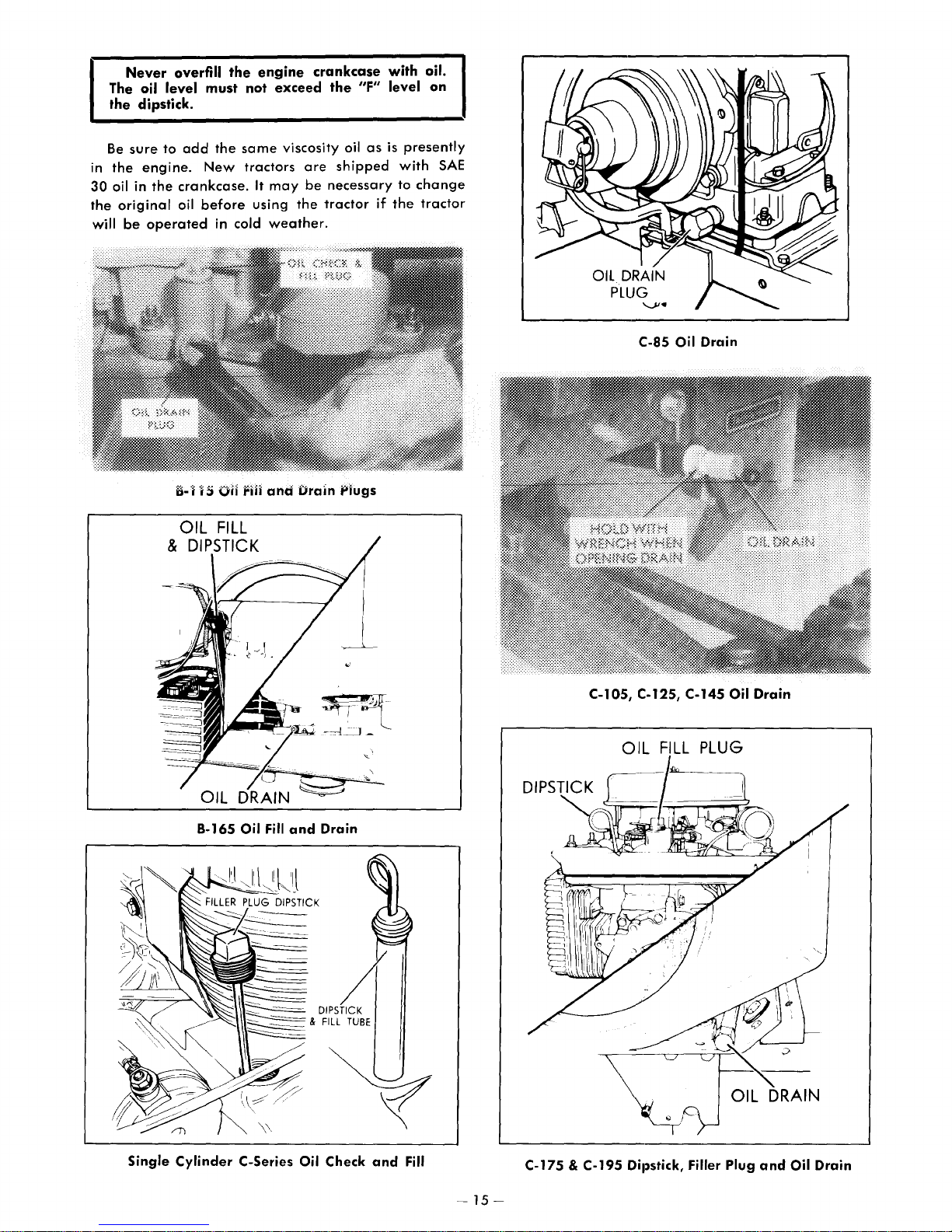
Never
The oil level
the
dipstick.
Be
sure
in
the
engine.
30
oil in
the
original
will
be
operated
overfill
to
add
the
crankcase.
oil
the
must
the
New
before
in cold
engine
not
exceed
same
tractors
It
may
using
weather.
crankcase
the
viscosity oil
are
shipped
be
necessary
the
tractor
/IF"
as
if
with oil.
level
on
is
presently
with
to
change
the
tractor
SAE
C·85 Oil Drain
8·165
Oil
Fill
and
'-\\11~2;;=
&
Drain
A
DIPSTICK
FILL
TUBE
C·l05,
\
C.125, C·145 Oil Drain
OIL
FILL
PLUG
~.~~~
~
J OIL DRAIN
Single Cylinder C·Series Oil Check
and
Fill
C·175 & C·195 Dil)stick, Filler Plug
-
15-
and
Oil Drain
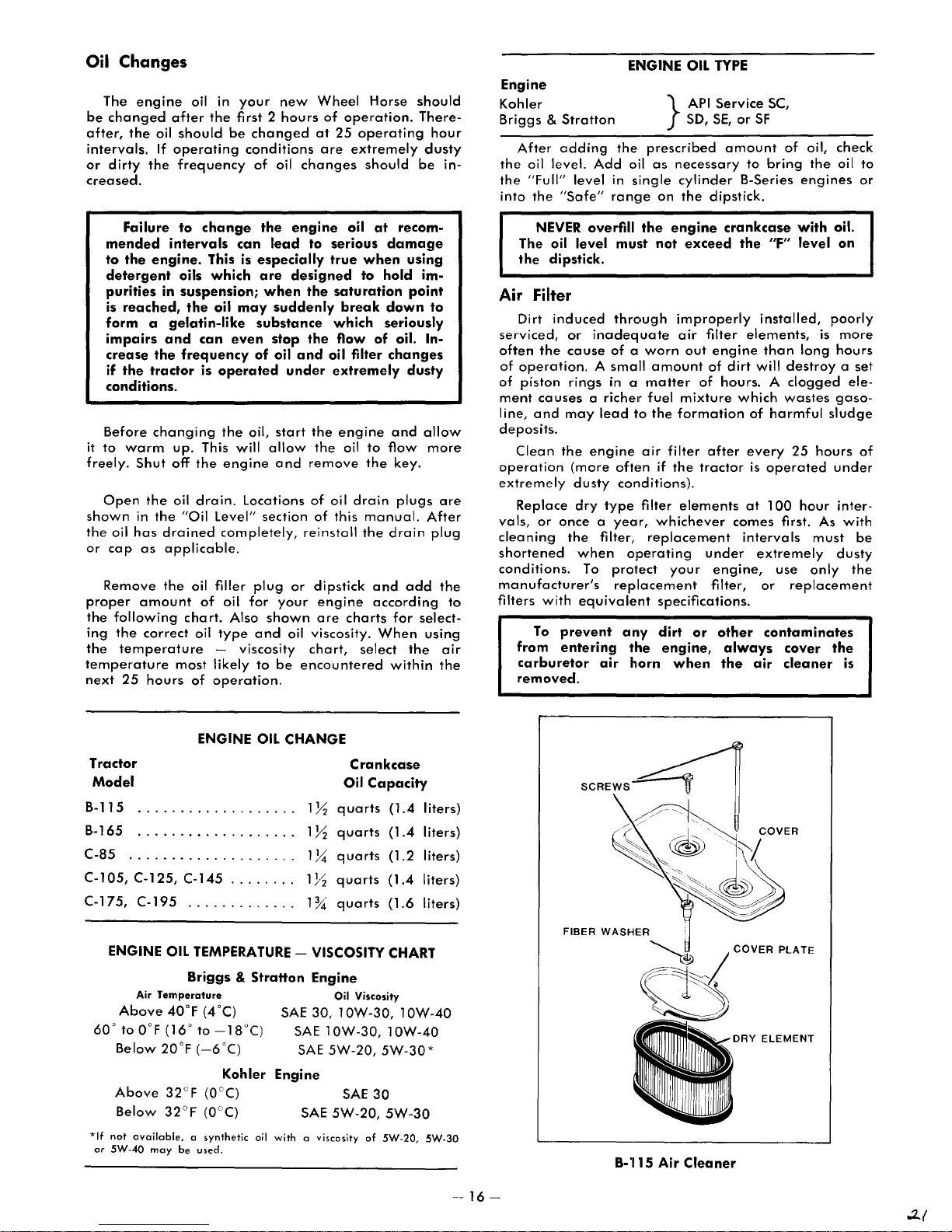
Oil
Changes
The
be
changed
after,
the
intervals.
or
dirty
creased.
engine
oil
If
the
oil in
after
the
should
operating
frequency
your
first 2
be
changed
conditions
of
new
hours
oil
Wheel
of
at
25
are
changes
Horse
operation.
operating
extremely
should
should
There-
hour
dusty
be
in-
Engine
Kohler
Briggs
After
the
oil level.
the
"Full" level
into
the
&
Stratton
adding
"Safe"
ENGINE OIL
the
Add
oil
in
range
}
prescribed
as
necessary
siingle
on
TYPE
API
Service
SE,
SO,
cylinder
the
dipstick.
or
SF
amount
to
B-Series
SC,
of
bring
oil,
check
the
oil to
engines
or
Failure
mended
to
the
detergent
purities
is
reached,
to
intervals
engine.
oils
in
suspension;
the
form a gelatin-like
impairs
crease
if
the
and
the
frequency
tractor
conditions.
Before
it
to
freely.
Open
shown
the
or
Remove
proper
the
ing
the
temperature
next
changing
warm
Shut
the
in
the
oil
has
drained
cap
as
the
amount
following
the
correct
temperature
25
hours
up.
off
oil
"Oil Level" section
applicable.
oil filler
chart.
most
of
change
can
This is
which
oil
may
can
even
is
operated
the
This will
the
engine
drain.
Locations
completely,
of
oil
Also
oil
type
- viscosity
likely
operation.
the
engine
lead
especiglly
are
designed
when
suddenly
substance
stop
of
oil
under
oil,
start
allow
and
plug
or
for
your
shown
and
oil viscosity.
to
be
oil
to
serious
true
when
to
the
saturation
break
which
the
flow
and
oil filter
extremely
the
engine
the
oil
remove
of
oil
drain
of
this
reinstall
the
dipstick
engine
are
charts
chart,
select
encountered
at
recom-
damage
using
hold
point
down
seriously
of
oil. In-
changes
dusty
and
to
flow
the
key.
plugs
manual.
drain
and
add
according
for
When
the
within
im-
to
allow
more
are
After
plug
the
select-
using
air
the
to
NEVER
The oil
the
overfill
level
dipstick.
Air Filter
Dirt
induced
serviced,
often
of
operation. A small
of
piston
ment
line,
deposits.
Clean
operation
extremely
Replace
vals,
cleaning
shortened
conditions.
manufacturer's
filters
from
carburetor
removed.
or
the
cause
rings
causes
and
may
the
(more
dusty
dry
or
once a year,
the
when
To
with
equivalent
To
prevent
entering
a richelr
engine
the
must
through
inadequate
of a worn
amount
in a
matter
fuel
lead
to
the
air
often
conditions).
type
filter
filter,
replacement
operating
protect
replacement
arlY
the
air
horn
engine
not
crankcase
exceed
improperly
air
filter
out
engine
of
dirt
of
hours. A clogged
mixture
which
formation
filter
after
if
the
tractor
elements
whichever
comes
under
your
engine,
filter,
specifications.
dirt
or
other
engine,
when
always
the
the
"F"
installed,
elements,
than
will
destroy a set
wastes
of
harmful
every
is
operated
at
100
first. As
intervals
extremely
use
or
replacement
contaminates
cover
air
cleaner
with
level
long
25
hour
is
sludge
hours
must
only
oil.
on
poorly
more
hours
ele-
gaso-
of
under
inter-
with
be
dusty
the
the
is
Tractor
Model
B-115
B-165
C-85
.................
C-l05,
C-175,
ENGINE
Above
60'
to
Below
Above
*If
not
available, a syntheti<
or
5W-40
ENGINE
...................
...................
C-125,
C-195
Air
OIL
Temperature
40°F (4°C)
OaF
(16'
20'F
32cF (O°C)
may
C-145
.....
.............
TEMPERATURE
Briggs & Stratton
to
-18°C)
(_6°C)
Kohler
be
used.
OIL
CHANGE
Oil
lY;
quarts
lY;
quarts
" .
" . lY;
1~
1%
quarts
quarts
quarts
- VISCOSITY CHART
Engine
Oil Vi.<osity
SAE
30,
10W-30,
SAE
10W-30,
SAE
5W-20,
Engine
SAE
SAE
5W-20,
oil
with
a vis<osity
Crankcase
Capacity
(1.4
(1.4
(1.2
(1.4
(l.6
10W-40
10W-40
5W-30*
30
5W-30
of
5W-20,
liters)
liters)
liters)
liters)
liters)
5W-30
SCREWS
B-1I15
Air
Cleaner
COVER
PLATE
-16-
..2..(
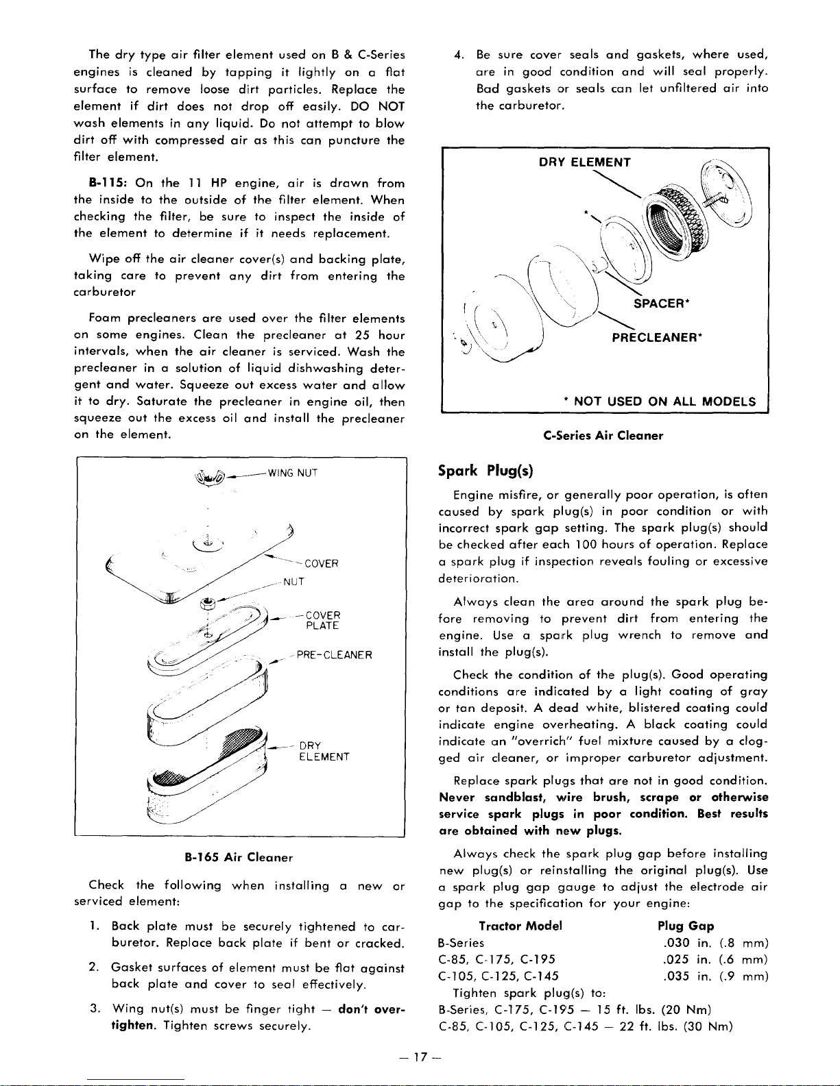
The
dry
engines
surface
element
wash
elements
dirt
off
filter
element.
B-115:
the
inside
checking
the
element
Wipe
taking
carburetor
on
intervals,
precleaner
gent
it
squeeze
on
Foam
some
and
to
dry.
the
care
element.
type
air
is
cleaned
to
remove
if
dirt
in
with
compressed
On
the
to
the
the
filter,
to
determine
off
the
air
to
precleaners
engines.
when
in a
water.
Saturate
out
the
filter
by
loose
does
any
11
HP
outside
be
cleaner
prevent
are
Clean
the
air
solution
Squeeze
the
excess
element
tapping
dirt
not
drop
liquid.
air
as
engine,
of
the
sure
to
if it
cover(s)
any
used
the
cleaner
of
liquid
out
precleaner
oil
and
used
it
lightly
particles.
off
easily.
Do
not
this
can
air
filter
inspect
needs
and
dirt
from
over
the
precleaner
is
serviced.
dishwashing
excess
water
in
install
on
B &
C-Series
on a flat
Replace
DO NOT
attempt
is
element.
replacement.
engine
the
puncture
drawn
the
inside
backing
entering
filter
elements
at
25
Wash
and
oil,
precleaner
to
the
blow
the
from
When
plate,
the
hour
the
deter-
allow
then
of
4.
Be
sure
cover
are
in
good
condition
Bad
the
carburetor.
gaskets
or
DRY
I ( \
.
~\J
~
C-Series
seals
and
seals
can
ELEMENT
~
';)
';;;;.CLEANER"
*
NOT
USED ON
Air
gaskets,
and
will
let
SPACER"
Cleaner
where
seal
unfiltered
ALL
MODELS
used,
properly.
air
into
Check
serviced
1.
Back
buretor.
2.
Gasket
back
3.
Wing
tighten.
-.
/ /
~
• T
"
the
following
element:
plate
Replace
surfaces
plate
nut(s)
Tighten
~
__
~-:.~----
~
4
I
;/~'
/'
~
Air
when
be
back
of
element
cover
be
screws
J
-;/
"
Cleaner
securely
plate
to
finger
.
<~£'
B-165
must
and
must
WINGNUT
----COVER
NUT
-~-
'~
-COVER
---
- PRE-CLEANER
_--
DRY
ELEMENT
installing
tightened
if
must
seal
tight -don't
securely.
PLATE
a
bent
or
cracked.
be
flat
effectively.
new
to
car-
against
over-
or
Spark
caused
incorrect
be
a
deterioration.
fore
engine.
install
conditions
or
indicate
indicate
ged
Never
service
are
new
a
gap
B-Series
C-85,
C-l05,
B-Series,
C-85, C-1
Plug(s)
Engine
checked
spark
Always
Check
tan
Replace
Always
spark
Tighten
misfire,
by
spark
plug
removing
Use a
the
the
deposit. A dead
engine
an
air
cleaner,
sandblast,
spark
obtained
plug(s)
plug
to
the
Tractor
C-175,
C-125,
C-175,
05, C-125,
or
generally
spark
after
clean
plug(s).
are
"overrich"
spark
check
specification
spark
plug(s)
gap
setting.
each
if
inspection
the
area
to
prevent
spark
condition
indicated
overheating.
or
improper
plu'gs
wire
plugs
with
or
gap
Model
C-195
C-145
in
new
the
spark
reinstalling
gauge
plu!;J(s) to:
C-19'5 - 15 ft. Ibs.
(-145 -22
in
100
hours
reveals
around
plug
of
the
by a light
white,
fuel
mixture
that
are
brush,
poor
plugs.
plug
to
for
poor
poor
The
spark
of
fouling
dirt
wrench
plug(s).
blistered
A
black
carburetor
not
scrape
condition.
gap
the
original
adjust
your
engine:
ft. Ibs.
operation,
condition
plug(s)
operation.
the
spark
from
entering
to
remove
Good
coating
coating
coating
caused
in
good
or
before
the
electrode
Plug
Gap
.030
.025
.035
(20
Nm)
(30
is
often
or
with
should
Replace
or
excessive
plug
bethe
and
operating
of
gray
could
could
by a clog-
adjustment.
condition.
otherwise
Best
results
installing
plug(s}. Use
air
(.8
(.9
Nm)
mm)
mm)
mm)
in.
in. (.6
in.
-
17-

Breaker Points
The
following
tractors,
electronic
tenance.
The
greatly
are
pass;
or
at
full
can
incorrect
The
cleaned,
the
condition
be
The
mize
operating
fer
If
the
of
A
shorted
results
The
breaker
Access
amount
some
ments
replacing
reasons,
be
which
ignition.
condition
affects
burned
as a result,
if it
does
throttle.
also
result
gap
engine
and
Maintenance
due
replaced.
primary
arcing
conditions, a small
(pitting)
condenser
the
points
condenser
in
no
condenser
points
to
of
cases,
affecting
or
it is
performed
engine
or
badly
run,
An
changes
the
to
across
will
will
output
are
the
disassembly
special
adjusting
suggested
by
and
Condenser
information
have
an
This
and
adjustment
operation.
oxidized,
the
engine
it is
improper
in
erratic
ignition
breaker
gap
reset
Checklist.
excessive
function
the
breaker
occur
fails,
excessive
occur
grounds
voltage
is
usually
changed.
breaker
tools.
engine
an
authorized
timing
the
does
not
engine
system
likely
engine
points
of
between
over a short
points
on
In
that
requires
of
the
If
little
may
not
to
"miss",
engine
operation,
timing.
should
at
the
intervals
Points
pitting
the
replaced
breaker
or
condenser
points.
amount
the
pitting
the
ig
to
fire
requires a significant
some
addition,
may
be
ignition
dealer.
apply
with
breaker
the
point
or
no
operate
breaker
be
that
are
burning
Under
of
point
period
nition
the
spark
each
engines
other
necessary
points.
system
to
B-Series
breakerless
no
main-
points
surfaces
current
at
particularly
point
gap
since
inspected,
shown
in
poor
should
is
to
mini-
normal
metal
trans-
surfaces.
or
burning
of
time.
system
plug(s).
time
and,
adjust-
For
service
and
after
these
will
all,
an
in
the
in
A.
Black,
B.
Engine
C.
Engine
weather
D.
Engine
POSSIBLE
A.
Mixture
B.
Mixture
C.
Mixture
D.
Idle
ment -readjust
if
needed.
Fuel Filter
A
fine-mesh
into
the
fitting
filters
reaches
service
taminated.
removing
entering
storage
condition.
moisture
during
er
tank.
fuel
shou
or
foreign
the
only
Always
the
container
The
fuel
winter
conditions
Some
tractor
filter,
Id
be
at 1 year
it
in
sooty
misses
starts,
starting.
runs
too
too
too
speed
CarburE!tor
screen
at
matter
carburetor.
if
the
clean
the
to
prevent
fuel
filter
gives
the
fuel
operation,
can
en9ines
located
replaced
intervals,
CONDITION
exhaust
and
sputters
rough
smoke,
backfires
and
or
stalls
at
CAUSE/PROBABLE
rich -
lean -readjust
lean -readjust
too
the
fuel
system.
you
C<:Iuse
after
low
speed
Adjustment
type
bottom
from
This
supply
area
around
excessive
are
only
system.
when
moisture
may
near
each
whichever
readjust
or
improper
then
strainer
of
the
strainer
becomes
Also
using
limited
Keep
cold
also
the
carburetor.
100
the
gasoline
the
amounts
insure
is
clean
to
hou
occurs
engine
at
high
dies
under
idle
speed.
REMEDY
main
fuel
main
fuel
main
fuel
idle
idle
fuel
Chart
is
incorporated
fuel
tank,
normally
severely
fuel
cap
of
that
and
protection
the
fuel
and
damp
condense
have
an
This
rs
of
first.
sluggish.
speed.
cold
needle.
needle.
needle.
adjust-
needle
which
before
requires
con-
before
dirt
from
the
fuel
in
good
against
tank
full
weath-
in
the
in-line
filter
operation
it
Carburetor
Carburetors
not
have
conditions
justed
correct
heating,
black
exhaust
first -
poorly
improperly
Correct
amount
such
as a good
ments,
sary
after
it
is
suggested
formed
Adjustment
are
to
be
reset.
is
noted,
immediately
setting
an
serviced,
such
by
excessive
"overrich"
adjusted
carburetor
of
knowledge
as
adjusting
an
can
smoke
clogged
tachometer.
governor
that
authorized
adjusted
If,
however,
the
carburetor
as
continued
lead
to
valve
is
noted,
mixture
air
carburetor.
adjustment
as
setti
the
carburetor.
carburetor
in
fouled
wear
cleaner
well
In
ngs,
dealer.
the
one
or
check
is
usually
requires a significant
as
addition,
adjustments
factory
of
the
should
operation
spark
other
the
caused
element,
special
other
may
a Iso
For
these
and
should
following
be
read-
with
plugs,
problems.
over-
air
cleaner
by
not
equipment,
adjust-
be
neces-
reasons,
be
in-
an
per-
CHARGING
ELECTRICAL SYSTEMS
Alternator
An
alternator
If
service
posed
a
are
damage
-18-
alternator
chargin9
other
wiring
clean,
equipped
the
ing
all
reconnecting
result.
tight
Proper
polarity
battery
on
any
components
to
AND
is
than
periodically
and
electrical
and
charging
ground
part
t:Jre
the
alternator
used
system
in
is
system.
cable
of
the
ground
to
charge
normally
connections
good
condition.
critical
(negative)
electrical
connected
cable
system
the
checking
with
an
Always
before
system.
correctly
(negative)
components
battery.
requires
that
on
the
alternator
disconnect
work-
Verify
before
The
no
all
ex-
tractor
or
will

Never
moved,
charging
system
Main
Fuse
A
25
motive
control
is
sole,
(B-Series).
type
circuit
attached
just
run
the
or
if
the
system.
components
amp
(C-Series)
ATO
of
the
to
the
behind
engine
battery
Serious
or
ATC
electrical
center
the
may
or
fuse
"rib"
battery
if
the
is
not
damage
result.
15
amp
is
system.
inside
(C-Series)
battery
connected
to
(B-Series)
used
to
The
the
or
is
to
the
charging
protect
fuse
holder
control
fuel
re-
auto-
the
con-
tank
C-SERIES:
The
light
the
battery.
switch
type
ATO
fuse
holder
console
is
(see
circu it
in
or
is
The
lights
the
Run
ATC
attached
Main
on
C.·Series
will
operate
position. A 15
fuse
is
part
to
the
Fuse,
preceding).
tractors
of
center
Hour Meter Fuse (C-195 Only)
The
fuse.
tion
the
C-195
The
switch
battery.
fuse
and
hour
holder
the
meter
is
hour
is
protected
connected
meter
Battery
&.
CAUTION
When
of
the
removed
negative
LAST
to
servicing
electrical
for
(ground)
avoid
the
battery
~;ystem,
any
reason,
cable
the
possibility
or
always
FIRST
if
the
the
and
&.
or
battery
and
of
electrical
is
powered
when
the
amp
automotive
light
rib
of
by
a 6
between
is
located
any
other
disconnect
reconnect
by
ignition
circuit. The
the
control
amp
SFE
the
igni-
behind
part
must
be
the
it
shorts.
Light Circuit
B-SERIES:
alternator
The
circuit
for
this
engine
D.C.
age
this
reason
Never
battery
to
for
operating
circuit
running.
interconnect
the
charging
/ )
B·SERIES
)'
C·SERIES
B &
C-Series
and
Fuse
on
is ALTERNATING CURRENT
the
lights
circuit
B-Series
the
will
the
as
this
system.
Fuse
lights.
not
A.C.
may
Locations
tractors
The
operate
light
result
has a separate
alternator
circuit
in
output
(A.c.).
without
and
serious
For
the
the
dam-
Maintain
each
cell
best
time
tractor
not
overfill
rosive
ing
metal
1.260
been
connect
before
The
be
add
and
can
water.
For
clean
sion
around
by
applying a solution
four
parts
applied
corrosion.
At
charge
electrolyte
battery
Light Bulb
Headlight
ped)
are
be
taken
they
are
Either
first
disconnecting
the
headlamp
clips
90
To
replace a tail
a
screwdriver. A slot
lens
for
push
remove
the
bulb
:#
1895
the
by
addin~l
to
add
so
the
the
and
overfilling
parts.
specific
out
of
the
the
cables
removal.
electrolyte
inspected
water,
remove
then
be
longest
by
wiping
the
water. A light
to
all
temperatures
state
from
damage.
Replacement
and
replaced
when
broken.
sealed
to
release
this
purpose.
the
bulb
it.
If
the
straight
(metal
water
gravity
disconnect
service
exposed
base)
electrolyte
distilled
water
battery.
ThE!
if a
the
slid
it
battery
must
tail
handling
beam
is
down
bulb
out.
is
will
The
can
battery
charge.
tractor
t()
off
frt~ezing
both
installed,
for
the
battery
level
mirror
the
battery
out
enough
life,
with a paper
terminals
of
terminal
below
be
maintained
light
as
described
headlamp
terminal
the
headlamp.
light
bulb,
is
located
If
the
and
has a plastic
Tail
or
:#
194
level
water
just
prior
mix
with
electrolyte
cause
damage
should
When
servicing,
on
B-Series
and
battery
hold
the
battery
one
coating
32°F
and
causing
bulbs
the
bulbs,
then
pry
bulb
turn
light
bulbs
(all
above
exactly
light
down.
to
part
surfaces
(on
below.
wires.
at
has a metal
counterclockwise
glass).
as
to
the
be
the
are
ground
permit
towel.
should
baking
of
grease
(O°C),
to
models
unit
turn
the
each
socket,
are
the
plates
necessary.
operating
solution.
solution
to
surround-
maintained
battery
take
as
they
tractors
used.
The
battery
adding
should
Any
be
removed
to
the
prevent
permanent
so
Care
particularly
is
replaced
Note
the
the
retaining
lens
off
end
simply
automotive
The
the
is
cor-
has
care
were
can
To
cable
be
kept
corro-
soda
may
prevent
full
cell
equip-
should
by
way
with
of
the
socket,
pull
in
Do
at
to
to
be
if
to
-19-

AUTOMATIC TRANSMISSION
Oil Quality
C-SERIES.
The
hydrostatic
requires
of
B-SERIES:
The
requires a straight
motor
The
premium
10W-30
hydrostatic
oil,
transaxle
or
API
Oil Level
transmission
quality
10W-40.
Service Classification
requires
Use
transmission
SAE
20
SAE
motor
only
weight
90
in
oi
premium
in
EP
your
I,
with
your
premium
SC,
gear
Wheel
a viscosity
quality
Wheel
SO,
oil.
quality
SE,
Horse
oil.
Horse
or
SF.
B-SERIES:
The
lubricant
use. The oil
of
the
tractor. The
when
the
oil is cold; if
add
oil
as
looking
unscrew
oil
NOT
transmission
through
through
OVERFILL
Use
foreign
during
the
care
oil level checks, oil fillings,
level
reservoir
required.
the
cap
from
the
hole
the
damage,
to
prevent
material
should
can
be
most
accurate
the
oil is
If
the
oil level is not visible
reservoir
the
reservoir
in
the
fender
transmission.
can
result.
dirt,
from
be
checked
observed
reading
below
or
if oil
under
clippings
entering
before
from
the
is
obtained
the
cold fill line,
must
be
and
observe/add
the
seat.
Overheating
or
other
transmission
or
oil
changes.
each
rear
by
added,
DO
and
C-Series
C-SERIES:
The
lubricant
use. The dipstick. is.
from
the
cl~an
with a clean
stick
and
ta.ined
stick.
or
essary.
seated
between
Never
ABOVE
Replace
in
Use
foreign
ing
oil level checks, oil fillings,
CHECK
C-Series -
Automatic
(C-145/C-175
level
transmission.
remove
the
operate
the
marks
the
the
filler
care
to
material
OIL
should
located
Remove
lint
again.
"F"
the
on
dipstick,
tube.
prevent
from
Correct
Transmission
Shown)
be
checked
in a filler
the
dipstick
free
rag.
The oil level
and
"L"
tractor
the
dirt,
entering
Transmission
levels
with
dipstick.
making
clippings
transmission
or
Dipstick
before
tube
coming
and
Replace
should
on
the
oil
Add
oil
sure
it
or
oil
changes.
DO
NOT
EXCEED
FULL
MARK
Oil Level
the
be
main-
the
BELOW
as
is
other
dur-
each
up
wipe
dipdipnec-
fully
The
transaxle
hours. Check
check
the
oil level,
transaxle
bottom
Oil
C-SERIES:
Drain
or
after
first.
The oil is
the
bottom
the
case.
of
filler
Changes
and
100
left
rear
B-Series
oil level
the
The oil
plu~1
B-Series
refill
hours
drained
of
the
end
Transmission
oil level
remove
should
hole.
Transaxle
the
transmission
of
operation,
by
transaxle.
of
the
transaxle.
Oil Level
should
removing
when
the
Oil Level
The
be
be
plug
checked
the
oil is cold.
filler
plug
maintained
oil
once
whichever
the
pipe
is
every
from
per
plug
located
25
To
the
at
the
year,
occurs
at
near
-20-

Because
check
vent
capacity
the
the
transmission
overfilling
is 5
quarts
transmission
oil
the
system.
(4.7
liters).
B-SERIES:
Changing
transmission
for
major
the
transmission
which
For
information
Hydrostatic
Transaxle
service.
should
the
lubricant
or
the
If
or
be
corrected
purposes,
Transmission
. . . . . . . . .
transaxle
oil
must
transaxle,
Oil Filter (C-Series Only)
Replace
operation.
transmission
whichever
the
oil
Thereafter,
oil
change
occurs
first).
filter
after
replace
will
not
level
while
The
in
either
is
not
frequently
a
immediately.
oil
capacities
...
..
1
Ys
qt.
the
the
(100
hours
drain
completely,
refilling,
approximate
the
hydrostatic
required
be
leak
is
indicated,
are:
%
qt.
(.7 l) SAE
(1.3
l)
SAE
first
10
filter
with
or
one
to
except
added
90
hours
pre-
refill
to
20
EP
of
each
year,
a-SPEED TRANSMISSION
Oil
Quality
The
mechanical
Horse
be
Transmission
a-Speed
used
is filled
whenever
Oil Level
The
lubricant
25
hours
of
required
level
Maintain
remove
Use
foreign
ing
oil
except
oil
care
level
operation.
at
material
with
level
for
the
the
to
checks,
dipstick
transmission
gear
oil.
the
transmission
Oil
SAE
API
Service
GL-5
should
Changing
major
service.
from
"full"
level
prevent
from
entering
oil fillings,
The
140
be
dirt,
in
same
checked
the
To
the
transmission
on
the
clippings
transmission
or
your
type
needs
lubricant
check
dipstick.
oil
new
Wheel
oil
filling:
Capacity
2
qt.
(1.91)
after
every
is
lubricant
or
other
dur-
changes.
must
not
case.
Cooling Fan
A
cooling
shaft
(located
forces
the
comes
maximum
On
facturer's
side
nificant
the
suggested
authorized
kept
spect
accumulated
equipment
and
system.
air
transmission
cracked
C-Series
name
with
the
amount
fan
on
The
cooling
clean
for
dirt
seal
areas,
over
airflow
that
dealer.
for
is
fan
is
bolted
just
behind
the
transmission
oil.
or
broken.
is
tractors
B-Series
the
faces
manufacturer's
of
disassembly
fan
replacement
fins
on
best
cooling
buildup,
dirt
or
used,
avoid
to
to
the
Replace
Be
directed
side
out;
tractors.
the
transmission
efficiency.
and
clippings.
directing
prevent
the
right
the
sure
across
of
the
on
name
For
brush
forcing
transmission
footrest).
cooling
cooling
to
install
the
fan
with
B-Series
faces
is
required
this
be
performed
or
If
pressure
the
water
The
fins
to
fan
if it
it
so
transmission.
the
manu-
tractors,
in. A
to
replace
reason,
by
should
Periodically
wash
spray
also
out
washing
at
into
input
fan
cool
be-
that
the
sig-
it is
an
be
in-
any
joints
the
S-SPEED
The
5-Speed
the
factory;
required.
TRANSMISSION
transmission
checking
the
is
packed
transmission
CHASSIS LUBRICATION
The
and
front
facilitate
Before
fittings
into
the
any
excess
grease
1
Front
steering
applying
carefully
fitting.
(lithium
Wheel,
gear,
spindles,
axle
pivot
are
lubrication
grease. A general
Spindle
with a pressure
the
grease
to
prevent
After
inserting
baSI;!)
is
t
1--_-
and
used
front
equipped
gun,
dirt
the
purpose
to
lubricate
Front
Axle
with
lubricant
wheel
with
grease
clean
from
being
grease,
pressure
/
Lube Fittings
grease
bearings
fittings
the
wipe
the
is
not
to
gun.
zerk
forced
off
gun
tractor.
at
-21-

lubricate
ation.
All
lubricated
purpose
wear
surfaces.
the
other
at
grease
chassis
pivoting
the
or
same
machine
after
each
arms
intervals
oil,
and
with
applied
25
levers
hours
either
of
oper-
should
general
directly
be
to
parking
of
the
skid
Then
ment,
the
rear
brake
band
brake
rod
both
tighten
the
is
engaged.
should
until the-
rear
the
parking
end
not
engolged,
wheels
nut
brake
of
the
With
"drag"
adjust
brake
when
another
lever's
the
on
band
lever
brake
the
the
~
slot
brake
the
nut
is
tight
tractor
turn.
should
when
released,
on
After
not
the
drum.
the
enough
is
pushed.
adjust-
travel
parking
the
brake
end
to
to
Steering
Gear
Lube Fitting
FOOT BRAKE ADJUSTMENT
5-Speed Models
The
brake
Block
the
and
place
brake
adjustment.
1.
Check
tacting
brake
pads
being
2.
With
nut
brake
off
the
check
The
brake
after
adjusting
of
force
applied
1.
The
washer
in. (6.8 - 7 cm).
required
adjustment
wheels
the
transmission
that
the
pedal
will
operated,
the
and
disc
the
adjustment
disc
to
that
rod
the
distance
on
to
the
drag
brake
tighten
is
turn
the
spring
to
the
to
prevent
transmission
back
stop
is
released.
on
causing
pedal
the
no
longer
freely.
brake
adjustment
brake.
the
brake
between
brake
obtain
is
made
shift
plate
the
disc
released,
adjustment
nut
Tighten
disc
This
the
rod
Turn
this
at
the
the
tractor
lever
brake
(or
If
it
does
while
premature
free
to
turn.
just
enough
the
is
still
should
determines
lever.
inside
should
the
adjustment
dimension.
brake
in
rod)
not,
the
loosen
nut
free
of
be
caliper.
from
rolling
Neutral
lever
is
when
the
tractor
brake
the
until
Next,
to
permit
lock
nut
to
be
checked
the
amount
the
nut
21K6 -2%
nut
for
con-
the
brake
wear.
lock
the
back
and
turn.
and
as
B-SpeE!d
Brake
Adjustment
C-Series Automatic Models
The
brake
is
transmission,
turn,
brakes
depressed,
dynamically
actuated
viding
also
serves
To
adjust
cover,
one
screw
1.
2.
3.
which
Set
in
done
lever
You will
it
Tighten
the
pressed,
Release
brake
band,
brakes
the
linkage
brakin<;J
after
the
additional
as
the
is sec:ured
at
the
the
parking
the
first
by
as
the
drops
into
the
coils
then
the
band
located
the
re(lr
returns
the
j'ransmission
braking
the
parking
brake,
bottom
brake
notch
pulling
brake
feel
the
the
nut
of
Ithe
back
parking
i!,
not
transmission
wheels.
the
tractor.
action.
brake.
remove
by
and a bolt
so
in
the
back
pedal
lever
first
notch
on
the
heavy
off
brake
dragging
on
the
left
As
the
transmission
The
reaches
The
the
two
screws
at
that
the
control
on
the
is
slowly
move
back
of
the
brake
the
linkage
spring
nut ~ turn.
and
on
the
side
shafts
brake
to
brake
neutral,
brake
left
hand
at
the
lever
cam.
parking
depressed.
slightly
control
are
fully
check
brake
of
and,
pedal
neutral,
band
the
front.
is
latched
This is
brake
bolt
that
drum.
the
in
is
is
pro-
band
side
top,
as
cam.
until
com-
the
S-Speed
Brake
Adjustment
B-Speed Models
The
To
brake
brakes
adjust
pull
transmission,
turn,
and
the
back
band,
brakes
the
brake
on
rear
the
located
the
transmission
wheels.
push
parking
on
down
the
brake
on
left
shafts
the
lever.
side
brake
With
of
and,
pedal
the
in
the
C-Series
--
22-
Automatic -Brake
(C-145/C-175
Shown)
Adjustment

If
the
pressed
the
tractor
authorized
C-Series
tractor
and
creeps
then
to
neutral
dealer
Automatic
(C-145/C-175
after
released,
should
requires
make
Brake
B-Series Automatic Models
The
brake
1.
With
2.
Slowly
distance
adjustment
tance,
If
the
changed
that
the
the
nut
adjustment
the
nut
and
brake
disc
off
the
the
disc
depress
overtravel
be
between
and
position
for
some
distance
and
the
brake
tighten
is
adjustment
to
turn
the
spring
nut
tighten
end
pedal
the
no
longer
freely.
the
brake
starts
:Va
and
as
of
the
reason,
between
of
the
is
made
nut
brake
lever
% in. (9.5 -
required
the
nut
it
the
rod
the
brake
the
linkage
adjustment.
this
adjustment.
Band & Drum
Shown)
at
the
released,
adjustment
free
to
just
enough
pedal
moves
to
compress.
to
lock
nut.
on
the
should
spring
is
7"~
be
in.
pedal
that
brake
loosen
nut
turn.
Next,
and
before
This
19mm).
obtain
brake
readjusted
side
(22mm).
is
returns
caliper.
the
until
to
permit
note
should
Turn
this
rod
(front)
de-
Your
lock
the
back
the
the
the
dis-
is
so
of
B-Series
To
adjust
1.
Engage
2. Loosen
bolt.
3. Turn
(.25
clutch
Check
4.
threaded
clutch/brake
(9.5 mm).
proceed
Loosen
on
ed
required,
the
brake
the
the
the
the
mm)
pulley
the
as
the
the
PTa
spacer
locknut
pad
B-Series PTO
PTa
clutch
PTa
clutch.
locknut
adiustment
gClp
between
face,
9ap
between
spacer,
bracket,
If
adjustment
follows:
locknut
rod;
turn
,clockwise
to
attain
and
recheck
Clnd
the
C-Series (Except C-195)
The
PTa
adjustment
If
c!utch
ther
onto
slippage
To
adjust
1.
Engage
2. Loosen
bracket
clutch
due
slippage
the
is
eliminclted.
clutch
the
the
the
to
to
is
PIa
PTa
two
the
and
normal
apparent,
rod
in
brake:
clutch.
bolts
support
and
on
the
bolt
the
then
tighten
on
the
which
behind
the
hex
or
the
proper
the
clutch
Adjustments
brake
wear
one
that
bracket.
may
turn
turn
brake:
PTa
brake
adjustment
so
there
brake
the
PTa
becomes
the
counterclockwise,
pulley
of
hold
is a .010
pad
the
hex
head
rod,
should
threaded
end
of
gap.
gap
between
face.
require
friction
the
trunnion
intervals
the
and
locknut.
and
be
necessary,
the
Retighten
periodic
surfaces.
until
brake
the
of
the
the
:Va
spacer
thread-
the
far-
the
pad
in.
in.
as
B-Series
If
the
pressed
the
tractor
authorized
PTO
CLUTCH
tractor
and
Automatic -Brake
then
to
dealer
creeps
neutral
after
released,
should
AND
the
the
requires
make
BRAKE ADJUSTMENT
The
PTa
clutch
adjustment
Adjustments
due
are
and
to
normal
made
brake
as
may
wear
follows:
Adjustment
brake
linkage
adjustment.
this
adjustment.
require
of
friction
pedal
that
surfaces.
is
de-
returns
Your
periodic
C-Series
-
23-
(Exc:ept
C-195)
PTO
Adjustments

3.
Place a .012
the
4.
While
gauge
bolts.
brake
holding
and
in. (.3
pad
the
pulley,
and
mm)
the
brake
tighten
feeler
clutch
pad
the
gauge
pulley.
against
two
brake
between
the
feeler
bracket
CLEANING
The
tractor
automotive
ed
surfaces
finish.
should
detergent
may
AND
be
and
be
waxed
STORAGE
washed
water.
to
regularly
After
protect
30
with
days,
the
a mild
paint-
original
C-195
The PTO
adjustment
If
clutch
1.
Engage
2.
loosen
the
(3.2
threaded
may
clutch
snowthrowing,
3.
Disengage
is a ~ in.
the
position
clutch
due
or
brake
the
the
threaded
mm)
be
increased
slips
clutch
of
and
to
norma I wear
slippage
PTO
clutch.
locknut
spacer
gap
between
spacer
under
etc.).
the
PTO
(6.4
mm)
rod
and
the
nut
brake
on
and
up
high
clutch
the
is
the
until
the
to
load
space
brake
on
may
require
of
friction
apparent:
clutch
there
the
hex
trunnion.
~ in.
applications
and
between
bracket.
the
rod,
rod
head
(6.4
check
if
periodic
surfaces.
and
is
a
of
This
mm)
(tilling,
that
the
nut
Adjust
necessary.
turn
Ya
if
there
in.
the
gap
the
on
the
Minor
paint
with
an
pound.
normal
bare
oil
can
Black
Authorized
period
minimum
Rubbing
circumstances,
metal
or
grease
be
made.
and
When
the
of
difficulty
1.
Perform
in
the
2.
Check
3.
Drain
tractor
gasoline
and
in
the
STORE GASOLINE
4.
Wash
su
rfaces.
scratches
automotive
compound
surfaces
to
prevent
Aerosol
linen
Beige
Wheel
tractor
time,
the
required
"Maintenance
tires
for
all
fuel
and
let
grows
forms
harmful
carburetor
the
tractor
cleaning
as
should
cans
Horse
will
following
when
proper
from
the
old,
or
abrasions
is
not
it
is
highly
be
given a light
rust
until
of
Wheel
are
available
Dealer.
not
be
the
unit
maintenance
Checklist".
inflation.
the
engine
it
gum
and
fuel
FOR
MORE THAN 2 MONTHS.
and
repaint
can
and
polishing
recommended
abrasive.
permanent
Horse
through
used
for
steps
will
is
returned
steps
fuel
tank.
run
out
becomes
and
varnish
pump.
all
be
an
help
less
bare
removed
under
Exposed
coating
repairs
Red,
Satin
extended
insure
to
service:
called
Start
of
gas.
volatile
deposits
DO NOT
metal
com-
of
your
for
the
As
C-195
PTO
Adjustments
5.
6.
Charge
40
F (4 C) a
for
about
(4
C)
the
battery
(more
tery
must
and
internal
(0 C).
Remove
the
the
often
the
battery.
battery
60
d(]ys~
water
"trickle
in
higher
be
flJlly
damage
key
In
In
level
charged"
charged
from
temperatures
will
maintain a charge
temperatures
should
temperatures).
in
the
be
every
to
prevent
weather
tractor.
lower
above
checked
30
The
freezing
below
than
40
and
days,
bat-
32
F
F
-24-

TROUBLESHOOTING CHECKLIST
SYMPTOM
Engine
Engine
start.
Engine
will
turns
hard
not
to
turn
over
start.
but
over.
will
not
POSSIBLE
Dead
battery.
Open
safety
Starter.
Solenoid.
Ignition
Spark
plug(s)
Breaker
(N/
A, B·Series).
No
fuel
Fuel
valve
Improper
Ignition
Spark
plug
or
loose.
Breaker
improperly
(N/
A, B-Series).
Spark
plug(s)
improperly
Coil,
condenser
defective.
Fuel
line
Fuel
pump
C-Series).
Carburetor
adjusted.
CAUSE
interlock
switch.
not
points
in
tank.
closed.
carburetor
switch.
wire(s)
points
gapped
faulty
gapped.
clogged.
faulty
dirty
firing.
faulty
grounded
faulty
or
magneto
(B-165,
or
switch.
adjustment.
or
or
improperly
POSSIBLE
Charge
Be
sure
depress
Consult
Consult
Consult
Check
spark
reset
gap.
Check
Consult
Refuel
Open
Reset
Consult
Check
Consult
Check
reset
Consult
Clean
in
Consult
Readjust
dealer
service.
fuel
carburetor
gap.
fuel
fuel
for
breaker
tractor.
spark
spark
tank.
REMEDY
or
replace
PTO
is
left
pedal.
authorized
authorized
authorized
plug
points
authorized
valve.
authorized
plug
authorized
plug
authorized
line;
authorized
carburetor.
authorized
battery.
disengaged
dealer.
dealer.
dealer.
condition
condition.
dealer.
adjustment.
dealer.
wires.
dealer.
condition
dealer.
check
strainer
dealer.
Consult
carburetor
and
and
and
Engine
erratically.
starts,
but
operates
Clogged
Water
Vent
Faulty
C-Series).
Improper
in
in
fuel
fuel
line.
fuel.
fuel
cap
pump
carburetor
-
plugged.
(B-165,
25-
adjustment.
Clean
in
fuel
Drain
fresh
supply.
Check
Consult
Readjust
fuel
line;
tank.
old
fuel
vent.
authorized
carburetor.
check
and
strainer
replace
dealer.
with

TROUBLESHOOTING CHECKLIST (Continued)
SYMPTOM
Engine
Engine
high
Engine
Engine
knocks.
occasionally
speed.
overheating.
idles
poorly.
"skips"
at
POSSIBLE
Fuel
octane
Incorrect
Engine
Spark
gap
Incorrect
Incorrect
Air
Oil
Fuel
Improper
Eng i
Improper
Improper
overheated.
plug(s)
too
intake
level
mixture
ne
overloaded.
CAUSE
too
low.
ignition
fouled,
wide.
ignition
carburetor
screen
too
high
too
ignition
carburetor
spark
timing.
timing.
adjustment.
or
fins
or
too
lean.
timing.
adjustment.
plug
faulty
clogged
gap.
low.
or
POSSIBLE
Drain
fuel
higher
Consult
Shut
cool.
Check
gap.
Consult
Readjust
Clean
Adjust
Readjust
Consult
Reduce
Readjust
Check
spark
octane
authorized
off
spark
intake
oil
the
plug(s).
REMEDY
and
supply.
engine
authorized
authorized
load
and
plug
carburetor.
screen
level
carburetor.
on
carburetor.
condition
replace
dealer.
allow
condition
dealer.
and
as
necessary.
dealer.
tractor.
and
with
fins.
gap
to
and
of
Engine
Engine
will
Tractor
tra
(Automatic
Engine
engaged.
not
nsm
backfires.
runs
loses
ission
stalls
fine,
move.
models)
but
power
overheats.
whenever
or
tractor
PTa
Improper
Fa u
(N/
Transmission
Faulty
Transmission
01
too
Transmission
resulted
at
low
oil.
is
Excessive
Faulty
carburetor
Ity
brea
A,
B-Series).
transmission.
low.
from
RPM
load
interlock
ker
poi
nts
clutch
oil
level
damage
operating
or
contamination
on
PTa.
system.
adjustment.
disengaged.
too
high
has
engine
of
Readjust
Consult
Engage
Consult
Adjust
Consult
authorized
Check
lessen
Seat
interlock
authorized
oil
for
load
must
carburetor.
authorized
clutch.
authorized
level
as
dealer
service.
jammed
on
be
occupied
system.
dealer.
for
attachment.
dealer.
dealer.
necessary.
attachments.
to
close
Consult
-
26-
S(
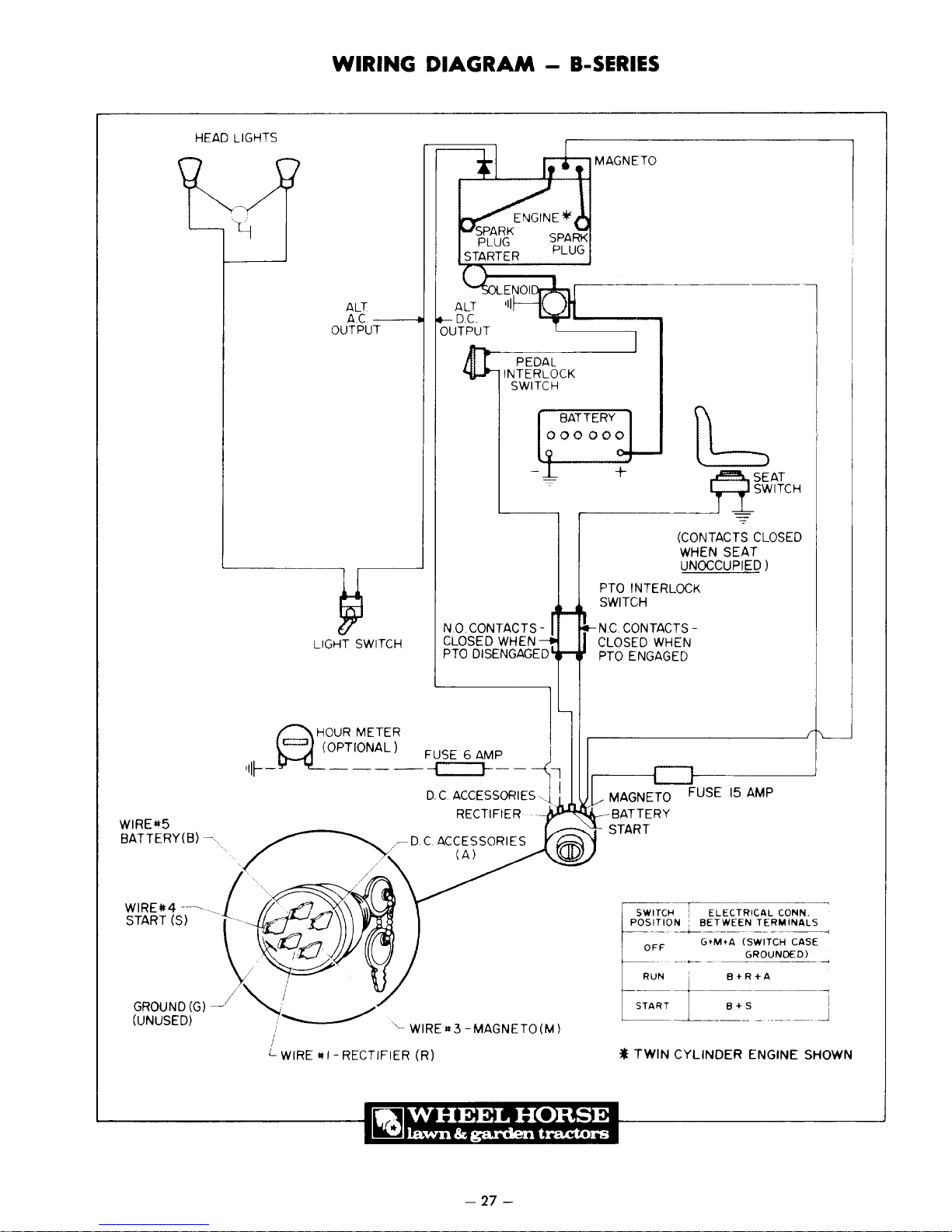
HEAD LIGHTS
WIRING
DIAGRAM
-
B-SERIES
ALT
A.C--~
OUTPUT
ALT
D.C.
OUTPUT
1r1I~---.------'
INTERLOCK
PEDAL
SWITCH
BATTERY
000000
+
,---
____
PTO INTERLOCK
SWITCH
N.0. CONTACTS-
LIGHT SWITCH
Q
H,OUR
METER
ql~_~OPTIONAL_)
CLOSED
PTO
_~SE
WHEN
DISENGAGED
6
~~_
~-l
N.C.
CONTACTS CLOSED WHEN
PTO
ENGAGED
~SEAT
~SWITCH
(CONTACTS CLOSED
WHEN
SEAT
UNOCCUPIED)
WIREit5
BATTERY(B)
~.
/
.~
GROUND(G)--J/
(UNUSED)
~~
/'--
L WIRE
It
/r-D.CACCESSORIES
/"
I - RECTIFIER
D.
C ACCESSORIES,j I
RECTIFIER .
(A)
WIRElt3
(R)
-MAGNETO(M)
-
27-
_IU'"~'"
SWITCH :
POSITION:
OFF
*
TWIN
FUSE
15
ELECTRICAL
BETWEEN
---+------
..
-------
GtMtA
__ +
____
._
CYLINDER
AMP
CONN.
TERMINALS
-.
__
.
~"-
----------1
(SWITCH CASE
..
<>ROUNDEO)
ENGINE SHOWN
..
~
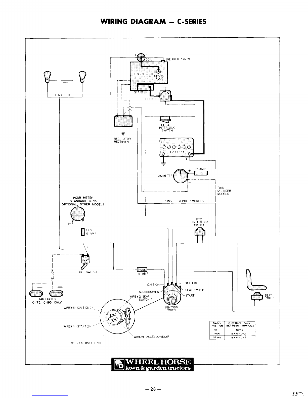
HEADLIGHTS
WIRING
REGULATOR
RECTIFIER
DIAGRAM
,,-~""'~_....r::::l"
-
C-SERIES
BRE
AKER ''(lINTS
l::;J
PEDAL
INTERLDCK
SWITC""i
000000
BATTERY
r---:---
-
····.·
..
···0
..
"::
:;-
M
C-175, C-195 ONLY
:
TAILLIGHTS
OPTIONAL,
'-------\
r~~~-
I
I
3
o
.-J
.-J
W
>-
_
i
1 =
..
·:····
... " ...
"
HOUR
METER
STANDARD,
C-195
OTHER MODELS
J~
n FUSE
y 5 AM"
\
'--1
----
L-
LIGHT SWITCY
______
)
'----+-----
~~
15
AMP I
IGNITION
ACCESSORIES
-=-
~++
AMMfTIR
SIN(;LE
fl'"
'~'L1NDER
_J1
-~-.,..""
....
SEAT
START
25AMP-l
FUSE
____
~_~
MODELS
PTO
INTERLOCK
SWITCH
-
SWITCH
IrWIN
CYLINDER
MODELS
I
I
1\
....
lb
•...
SEAT
WIRE>4
..
START(SI
WIRU
5 - BATTERY(8)
WIRUI-ACCESSORIES(RI
-28-
SWITCH
POSITION BETWEEN
~---t"~--
START
OFF
RUN
- -
~-
- -
ELECTRICAL
--
-----------
NONE
------
8+R+I+A
~I
-------
TER.
CONN
+'$
MINAL.
- -
----<
5 '
-----.
""
.......

P'(Jj,~,(:
t
"hdr,q,>
"otIU~
r1H'
(il
,]r1(j
p'oduct
IntufllldtlOrl
prlntJrlg
without
and
vVheel
specifications.
Irlcurrlng
speclf'LCltlons
Horse
Pro(Juc!',
designs
Obi
qat
,lft·
,>h')Wr1
herein
as
of
!r,(
.ld'
'eserves
1.1'd
Jr,.j
on
the
eqLJlprnpnt
fight
wlthour
thf-'
te'
.alWHEEL
:
~
lawn
&
garden
HORSE
tractors
 Loading...