

Networked AoIP Broadcast Console
Manufactured by Wheatstone Corporation
1

Publication Information
©2018 Wheatstone Corporation
Wheatstone con s ide r s this document and its contents to be proprietary and confidential. Except for making a reasonable number of copies for your own
internal use, you may not reproduce this publication, or any part there of, in any for m , by any method, for any purpose, or in a ny language other tha n English
without the written consent of Wh eatstone Corporation. All others uses are illegal.
This publication is de s igned to assist in the installation and use of the product as it exists on the date of publication of this manual, and may not reflect the
product at the cur r ent time or an unkn own time in the fu ture. This publication does not in any way warrant description accurac y or guarantee the use for the
product to which it r efers.
Wheatstone reser ves the right, without notice, to make such changes in equipment, de s ign, specificati ons, components, or documentation, as progress may
warrant, improving the perf orm a nce of the product.
Trademarks
Product names and other appropriate trademarks, e.g. WheatNet-IP™, VoxPro®, PR&E® are registered trademarks of Wheatstone Corporation or its
subsidiaries. Mic r osoft
respective companies.
®
and Windows® are registered tr a d em arks of Microsoft Corporation. All other tradem arks and trade n ames are the property of their
Customer Servi c e Contact Information
Wheatstone
600 Industrial Drive
New Bern, NC 28562 USA
For technical support, including on-site service, general product training, repair and parts, contact Wheatston e / PR&E through the webpage:
www.wheatstone.com; through email at techsupport@wheatstone.com; or by phone,+01 252-638-7000.
Manual Revisions
A = Initial release, Octobe r 2017
B = technical corrections, PR&E IP Navigator addition s , operational clar ifications, O c tober 2017
C = Appendix A on networking multiple consoles added; some technical corrections; consolidated software app info into chapter 3, July 2018
D = Added info on a new feature: saving/loading EQ Configuration files (DMX Surface S etup, build 1.0.29 and later), September 2018
D.1 = Added info a bout saving two Studio EXT selections, October 2018
D.2 = Changed exclamation point graphic to display pr op erly in a PDF, October 2018
2

TABLE OF CONTENTS
Publication Information .................................................................. 2
Safety Instructions & Hazard/Warning Labels .................................. 4
1 – Introducing the DMX Console .................................................... 5
DMX Overview ..................................................................... 6
DMX Specifications ............................................................ 7
Warranty Statement ............................................................ 9
FCC Compliance Statement ................................................. 9
2 – DMX Hardware Installation ........................................................ 10
Locating the DMX Components ............................................ 10
PR&E Mix Engine Connections ............................................. 12
DMX Power Up .................................................................... 13
Checking Out the DMX Features ........................................... 14
PR&E Mix Engine Signal Notes ............................................. 16
Additional DMX Features ..................................................... 17
Razor I/O Interface Notes ................................................... 19
3 – PR&E Apps and Console Configuration ........................................ 20
DMX Surface Setup App ...................................................... 20
PR&E Navigator App ............................................................ 31
PR&E System Configuration Tool .......................................... 43
Software Updates ............................................................... 44
4 – DMX Operation and Applications ................................................ 45
Console Operation .............................................................. 45
Using the Advanced Channel Features .................................. 51
DMX Applications ............................................................... 55
Razor I/O Interface ............................................................. 57
5 – DMX Service Information ........................................................... 58
Appendix A – Creating a PRE-IP Network ........................................... 60
3
4
1 – INTRODUCING THE DMX CONSOLE
T
hanks for joining the growing ranks of broadcasters
employing PR&E products, now designed, manufactured,
and supported by the Wheatstone Corporation.
Throughout PR&E’s long history we’ve endea v or ed to
provide the finest quality products , documentation , and after-sale support.
To obtain maximum be nefit from the DMX console’s capabil ities, please
read through this introduction and Chapters 2 and 3 prior to installing the
DMX console. For those in a hurry, a DMX Quick Guide (a PDF file on the
USB thumb drive th at ships with the console) summarizes the console’s
physical connections, software, and Surface controls.
The DMX console has these main components:
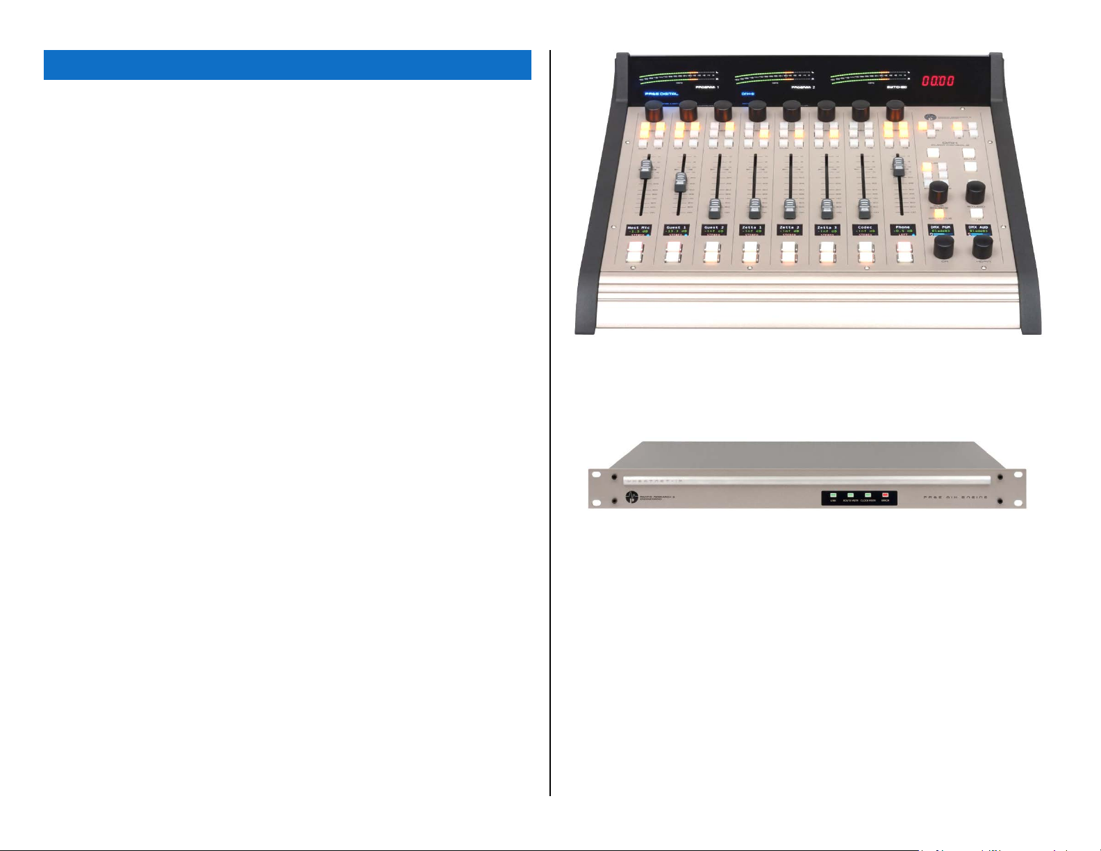
● DMX-8 or DMX-16 Surface – This part is commonly referred to as
the “console” s ince it sits on the countertop and ha s all of the board
operator controls. Figure 1-1 shows the DMX-8 Surface. The DMX
Surface has these features:
● Fader Channels – There are eight fader channels on the DMX-8
and sixteen on the DMX-16. Each fader channel has eight push
buttons with LE D illumination (channel on, channel off, cue on/off,
talkback (TB), and four PGM bus assigns), a color Organic Light
Emitting Diode (OLED) display to show channel status, a 100 mm
fader, and a rotary Channel Encoder to select the channel’s source.
The Channel Encoders also allow access to these Advanced Channel Features: audio mode, panning, and EQ & Dynamics settings,
any of which can be locked out for daily operations.
● Monitor Controls – The console supports a Control R oom and an
associated Studio with: CR monitor, CR headphone, Cue, and
Studio Monitor lev el controls; C R and Studio monitor sou rc e
selectors; timer controls; and four console Event buttons.
● Meter Bridge – There are three stereo LED meters showing PGM
1, PGM 2, and a Switched signal (PGM 3, PGM 4, EXT, and CUE, if
enabled). An On Air “Hot Mic” indicator and a four digit timer are
also included in the D M X meter bridge.
● Headphone outpu t – A board operator headphone amp is included in the DMX Surface with a ¼” TRS jack on the right side of the
chassis, in-line with the OLED displays.
Figure 1-1 DMX-8 Surface
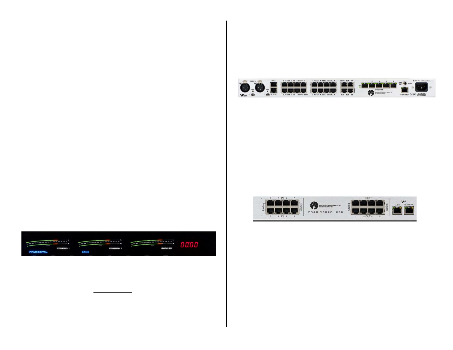
● PR&E Mix Engine – The 1RU Mix Engine (Figure 1-2) has the audio,
logic, and netw ork connections for the DMX console along with the
DSP, signal mixing, and AoIP (Audio over IP) interface functions.
Figure 1-2 PR&E Mix Engine, front panel
The PR&E Mix Engine has these main features:
● 5-port Gigabit Ethe r net switch to network the Surface and Engine,
along with three other Ethernet devic es , like an admin PC; audio
playback server; VoxPro PC; Razor I/O Interface; or a main AoIP
gigabit switch to network multiple DMX studios together
● Two low-noise mic preamps, with female XLR inputs, each with
switchable phantom power and input gain trim pot
● Eight stereo/dual mono inputs (four analog and four AES)
● Four stereo program outputs (analog and AES on each output)
● Four stereo analog outputs for Control Room, Studio, Cue, and an
operator headphone outp ut for an outboa rd amp
● One 6-port GPIO logic connector
5
● DC power source for the DMX-8 Surface (the DMX-16 Surface has
Figure 1-3 Surface Controls
DMX and EMX consoles a nd Razor I/O Interfaces are not
a separate in-line DC supply)
● Installation Kit – The DMX ships with a USB thumb drive with PDF
documentation files and the PR&E software application installers for
the three software apps used for console configuration . Note that PR&E
Navigator is a licensed application, so a site license (gratis) is required
to continue using it beyond a n initial evaluation period.
DMX-8 consoles include a n IEC AC power cord for the Mix Engine and a
DC cable for the Surface. DMX-16 consoles include an in-line DC supply for the Surface and two IEC AC power cords for the Mix Engine and
in-line supply. All consoles include a s hort CAT5e cable to con nect the
Mix Engine to its built-in Ethernet switch.
DMX OVERVIEW
The DMX console is a compact, self-contained, Audio over Internet
Protocol (AoIP) radio broadcast and production c onsole that uses the
WheatNet-IP (WNIP) AoIP netw or king convention. Designed for 24 / 7
operation, the console has two main hardware components: a 1RU rack
mount PR&E Mix Engine, which has all of the console’s audio and logic
connections plus a 5-port Gigabit Ethernet Switch; and a tabletop board
operator controller, called the Surface (which most users refer to as the
“console”). Both Surface and Mix Engine are fully FCC and CE certified.
The DMX console ships with a default configu r a tion so it can be powered
up and used straight out of the box. These default settings are quickly
changed, to configure the console for use in an on-air studio, production
room, newsroom, or other application, using the Windows PC apps that are
included with the console. Their use is c ov er ed in deta il in Chapter 3.
Razor I/O Interfaces (1RU, FCC and CE certified) are available to add
audio and logic I/O to any DMX console. Razors use RJ45 connectors for
audio (eight inputs a nd eight outputs ). They come in three I/O sty les: all
analog I/O with two mic preamps (Razor 16A); all AES I/O (Razor 16D);
or half analog and half-AES (Razor 16AD). Each Razor also has a 6-port
GPIO logic connector. Each Razor connects to a port on the Mix Engine’s
Gigabit Ethernet s witch using a single CAT5e or CAT6 cable of up to 330
feet (100 meters).
interoperable with a WNIP network because they lack
the Intellige n t Networking capabilities built into every
WNIP Blade. However, audio can be st reamed between
the PRE-IP devices and the WNIP devices when WNIP
Navigator is licensed for “cross-networking.” For details,
contact Wheatstone technical su pport, prior to
networking a WNI P a nd PRE-IP system toge th er, to
ensure that the two systems are running the code
required to support cross-network audio streaming.
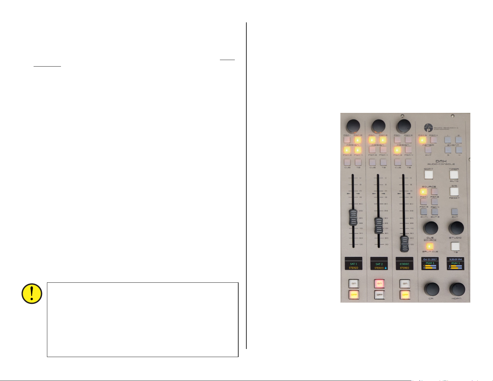
DMX Surface
The Surface’s eight or sixteen audio c ontrol channel strips are called
Fader Channels (three channels are shown in Figure 1-3along with the
monitor controls). Each fader channel has a large-knob rotary encoder to
allow the board operator to select the audio source for each fader channel.
The channel display, located just below each channel’s fader, shows the
name of the audio source currently “dialed up” on that channel along with
other source or channel status information. Rotating the encoder, while
the channel is off, switches the channel display to list alternate sources
that are visible on that channel. One source name is highlighted. Pressing
once or “clickin g” the rotary encoder “takes” that highligh ted s ource,
connecting it to that fader channel.
The fader channel’s
audio is assigned to any
combination of Program
buses using the four
assignment buttons just
below the channel
encoder.
Each fader channel has
a 100 mm fader for bus
level control, plus
illuminated Channel Off,
Channel On, Cue, and
Talkback (TB) buttons. All
of the fader channel
controls are iden tified in
Figure 4-2 on page 46.
At the right end of the
Surface are the Monitor
Controls. Each control and
display is identif ied in
Figure 4-4 on page 49.
The left column (CR) has
the Control Room con trols.
Three buttons at the top
select which source (PGM
3, PGM 4, or External) is
feeding the Switched
Meter. A large userdefined Soft button (no
default setting) is just above the six Control Room mon itor s ource select
buttons (PGM 1 – PGM 4, EXT 1, and EXT 2) which control which source
feeds the Control Room monitor s and board operator headphone output. A
Spilt Cue button sets how cue audio is fed to the hea dphones (if cue is set
to feed the headphones during console configuration).
6
The right column (STUDIO) has four Event buttons; two large Timer
control buttons; a studio monitor sou r c e s elector (EXT); and a large Talk
to Studio button (TB).
The CUE/SOURCE, CR, STUDIO, and HDPN controls are rotary encoders
used primarily to c ontrol the level of the four dedicated monitor outputs on
the Mix Engine. The two Monitor OLED displays show the current levels for
those four outputs and their status (a red X over a bar graph icon indicates
that output is muted).
The CUE/SOURCE and STUDIO encoders are also used to select and take
“wild sources” for the CR and Studio, and are used to assign sources to the
various EXT buttons.
The Surface controls are all on a sin g le field-replaceable Control Panel
that connects to an internal network interface board us in g one (DMX-8) or
two (DMX-16) plug-in ribbon cables. This allows for rapid field
replacement, with m inimal interruption to operations , in case of spills or
other damage to the Surface controls since the program audio is flowing
through the Mix Engine rather than through the Surface (except for the
audio to the side panel-mounted headphone jack).
Meter Bridge
The integrated direct-view Meter Bridge (Figure 1-4) sits above and
behind the control panel. It has three stereo level meters, a Timer, and an
On Air indicator. The left meter displays the Program 1 bus levels. The
middle meter displays the Program 2 bus levels . The right meter is
switchable between showing the other two program buses ( PGM 3 or PGM
4) or an External signal (EXT) like an off-air tuner signal. The switched
meter can also be set to auto-switch to show cue levels while cu e is active.
The meters normally show both the average and peak levels, but
software settin g s allow them to be changed to show only the average level
or only the peak levels for special functions.
powering); Signal Processing with EQ and dynamics (applied on a fader
channel basis); eight routable audi o inputs (four analog and four AES);
four Program audio o u tputs (four analog and four AES outputting the
same set of signals); four dedi c a ted analog output s (to feed powered
Control Room and Studio monitors, powered cue speakers, and an
outboard board operat or headphone amp); six GPIO logic contact s
(each independently set to fun c tion as a logic inpu t or logic output) and an
Ethernet jack to connect the Engine to the built-in Gigabit switch.
Figure 1-5 PR&E Mix Engine, rear panel
Input and Output Connectors
All audio, logic, and network connections on the Engine and on the
optional Razor I/O Interface (Figure 1-6)—other than microph one preamp
inputs which have female XLR connectors, use RJ45 connectors and
category wiring (CAT5, C AT 5e, or CAT6). Figure 2-4 on page 12 has wiring
pin outs for the RJ45 connectors used to connect analog audio, digital
audio, and logic to/f rom the DMX console.
Analog and AES wiring conforms to th e StudioHub+ con vention with two
balanced analog, or one AES/EBU (AES3) signal, per RJ45 jack.
The RJ45 Logic jack has six GPIO logic ports plus a +5V and a GND
connection which use the WheatNet-IP (WNIP) logic jack wiring format.
Figure 1-6 Razor 16AD Interface, rear panel RJ45 Connector Detail
Figure 1-4 DMX Meter Bridge
The four-digit Timer is controlled manually, using the Monitor section
S/S button (Timer Sta r t/ Stop control), or a utomatically , when the Auto
Timer button is lit and an au d io s ource, set for T imer R es et (assigned to
specific audio signals in the Surface Setup
app) is turned on.
PR&E Mix Engine
All audio and logic connections are made on the rear of the Mix Engine
(Figure 1-5). This 1RU device has a 5-port Gigabit switch; two highquality low-noise Mic Preamps (with gain control and 48-volt phantom
DMX SPECIFICATIONS
Test Conditions:
FSD = Full Scale Digital, 0 dB FSD equivalent to +24 dBu analog
0 dBu corresponds to 0.775 v olts R M S—regardless of the circuit
impedance, as measured using a 600 ohm circuit.
Noise specs measured using a 22 Hz – 20 kHz bandwidth. A 30k Hz
bandwidth increases the noise measurement by 1.7 dB.
Wheatstone / PR&E reserves the righ t to c hange the following
specifications without notice or obligation.
7

Mic Preamp
Source Impedance: 150 – 600 Ω, balanced
Nominal Input Level: -50 dBu
Input Rang e: -70 to -31 dBu (using trim control to reach nominal level)
Equivale nt Input Noise: -131 dBu
Logic GPIO
Six per RJ45 connector: Connection assignments made using PR&E
Navigator
Logic Inputs: Current-limited using internal pull-up. Supports +5 to +12
voltage logic. For a log ic low, input volta ge m ust fall below +2 .5 volts.
Logic Output: +5 to +24 VDC logic, 50 m A nominal, 100 mA max
(logic input or o utput; the type of log ic c ommand)
Analog I/O (Inputs & Outputs: +4 dBu, balanced)
Input Impedance: >10 k Ω, bridging
Optimal Source Impe dance: <1 k Ω
Analog In > Analog Out Frequen cy Response:
+0.0, -0.25 dB, 20 Hz to 20 kHz @ +4 dBu
Analog In > Analog Out THD & Noise:
<0.0025%, 20 Hz-20 kHz @ + 4 dBu
Nominal / Maximum Input Level: +4 dBu / +24 dBu
(±18 dB of level gain/trim control available in the PR&E IP Navigator)
Output Source Impedance: <10 Ω balanced
Output Load Impedance: 600 Ω optimal
Nominal / Maximum Output Level: +4 dBu / +24 dBu
(±18 dB of output leve l gain/trim contr ol in the PR&E IP Navigator)
A > D Conversion: 24-bit resolution
D > A Conve rsion: 24-bit, advanced Delta-Sigma
Digital I/O (AES/EBU Inputs & Outputs)
Reference Level: -20 dB FSD (equivalent to analog +4 dBu)
Nominal / Maximum Input or O utput Level: -20 dB FSD / 0 dB FSD
(±18 dB of level gain/ tr im control available in the PR&E IP Navigator)
Digital In > Digital Out Frequency Response:
±0.0 dB, 20 Hz to 20 kHz @ -20 dB FSD
Digital Input > Analog Output THD & Noise:
<0.00017%, 20 Hz-20 kHz @ -20 dB F SD
Signal Format: AES-3, S/PDIF (inputs only)
Digital I/O (continued)
AES-3 Input Compliance: 24-bit (uses SRC to support incoming s a m p le
rates of 32 – 96 kHz, 16- to 24-bit resolutions)
AES-3 Output Compliance: 24-bit
Output Sample Rate: 44.1 or 48 kHz
Processing Resolution: 24-bit
Surface Dimensions
DMX-08: 4.25" x 17.625" x 17" (H, W, D)
DMX-16: 4.25" x 29.625" x 17" (H, W, D)
DMX-16 Engine Dimensions
A 1RU rack-mounted device:
1.75" x 19.0" x 13.25" (H, W, D)
Razor I/O Interface Dimensions
A 1RU rack-mounted device:
1.75" x 19.0" x 9.25" (H, W, D)
Power Supply
Type: Internal switc hing supply on the Razor and the DMX-16 Engine,
which also powers the DMX-8 control surface; the DMX-16 Surface uses
a separate in-line switching DC power supply
AC input: Detachable IEC cord
AC input: 90-240 VAC, 50/60 Hz
Output: +16 VDC @ 1 amp (PWR OUT jack on DMX Engine)
Output: +16 VDC @ 2.67 amps (Surface in-line supply)
Power Requirements
DMX-16 Engine: <27 watts at 120 VAC / 60 Hz
DMX-08 Surface: <10 watts at 120 VAC / 60 Hz
DMX-16 Surface: <20 watts at 120 VAC / 60 Hz
Razor: <15 watts at 120 VAC / 60 Hz
Environment
Ambient Temperature: Less than 40°C
Cooling: Convection c ooled, no fans
8

WARRANTY STATEMENT
LIMITED WARRANTY BY WHEATSTONE CORPORATION
1. All equipment sold and shipped to final destinations w i thin the USA and its
possessions warranted for one (1) full year from the date of purchase against
defects in material and workmanship. All equipment sold and shipped to final
destinations outside the U.S.A. and its possessions warranted f or one (1) f ull
year from the date of purchase ag ainst defects in material and workmanshi p.
All repairs to maintain the unit at original specification will be made at no
charge to the original purchaser, except for shipping and insurance costs to be
prepaid by the owner to the factory in the event the unit cannot be serviced by
an authorized Wheatstone Corporation dealer.
2. This Warranty is subject to the following restrictions and conditions:
a) The owner must h ave filled out the en closed Warranty Card and returned
it to Wheatstone Corpor ation; or at the time of servi cing the owner must
provide proof of purchase from an authorized Wheatstone Corporation distributor or de aler.
b) This Warranty is valid for the original purchaser on the unit. Parts used for
replacement are warranted for the remainder of the original warranty period. Repair or replacement is in the discretion of Wheatstone Corporation
and is the exclu sive remedy hereunder.
c) This Warranty DOES NOT apply to damage or defects resulting from abuse,
careless use, misuse, improper installation, electrical spikes or surges, or
alteration, repair, or service of the unit or equipment by anyone other than
Wheatstone Corporation or its authorized dealer.
d) This Warranty is void if the serial number has been removed, altered or
defaced.
e) This Wa r ranty DOES N O T cover lo ss or damage, direct or in direct, arising
out of the use or inab il it y to use this unit or for s hi pping or transportation
to any dealer.
f) Wheatstone Corporation reserves the right to modify or change any unit in
whole or in part at any time prior to return delivery in order to incorporate
electronic or mechanical impro ve me nts d ee med appr opriate by the
Wheatstone Corp o r ation but without incurring any responsibility for modifications or changes of any unit previously delivered or to supply any new
equipment in accordance with any earlier specifications.
g) THERE ARE NO OTHER WARRANTIES, EXPRESSED, IMPLIED, OR STATUTO-
RY, INCLUDING ANY WARRANTIES OF MERCHANTABILITY OR FITNESS
FOR A PARTICULAR PURPOSE. IF FOR ANY REASON, ANY IMPLIED OR
STATUTORY WARRANTY CANNOT BE DISCLAIMED, THEY ARE LIMITED TO
THIRTY (30) DAYS FROM THE DATE OF PURCHASE. WHEATSTONE
COPORATION IS NOT RESPONSIBLE FOR ELECTRICAL DAMAGE, LOSS OF
USE, INCONVEN IENCE, DAMAGE TO O T HER PROPERTY, OR ANY OTHER INCIDENTAL OR CONSEQUENTIAL, WHETHER DIRECT OR INDIRECT, AND
WHETHER ARISING IN CONTRACT, TORT, OR OTHERWISE. NO REPRESENTATIVES, DEALERS, OR WHEATSTONE PERSONNEL ARE AUT HORIZED
TO MAKE ANY WARRANTIES, REPRESENTATIONS, OR GUARANTIESS OTHER THAN THOSE EXPRESSLY STATED HEREIN.
9

2 – DMX HARDWARE INSTALLATION
ach DMX Surface is 17” (43.2 cm) deep and 4 1/4" (11 cm)
tall. The DMX-8 Surface is 17 5/8" (45 cm) wide. The DMX16 Surface is 29 5/8” (75.3 cm) wide.
The PR&E Mix Engine (1RU) mounts within the studio
cabinetry below the Surface location. Install a 1RU blank panel, or mount
the Mix Engine at the top of the rack, to ensure adequate ventilation . All
DMX components are convection cooled so the y can be mounted into any
studio, includin g ones with active m ic r op hones, witho ut adding any
environmental noises. When locating the Surface and Engine, avoid close
proximity to device s which generate electromagnetic fields, such as large
power transform er s, motors, and audio amps using switching supplies.
LOCATING THE DMX COMPONENTS
The DMX Surface is designed to set on top of the studio furn iture
countertop with the fron t of its palm rest sitting between six and twelve
inches (15 to 30 cm) from the edge of the countertop (Figure 2-1). This
“setback space” allows keyboards and mice, a VoxPro controller, copy, log
sheets, etc. to be plac ed in front of the console.
The PR&E Mix Engin e (1 RU) is rack mounted in a 19” rack below the
countertop. It’ s typically loc ated near the top of a r a ck close to the DMX
Surface. The r e are no controls on the front panel, but there are four sta tus
LEDs on the front to indicate Engine status. The Engine’s rear panel must
be easily accessible since that’s where the audio, logic, and network
connections for the DMX cons ole a re m a de. We recommend adding a 1R U
blank or vent panel above the Mix En gin e to ensure adequate ventilation .
With a DMX-8 Surface, a 16-foot locking DC cable (included) connects
the Surface to the PWR OUT jack on the ba ck of the Mix Engine. This
constrains where the Mix Engine ca n physically be located s ince the DC
cable must not be under strain w hen connected between the Su r f ace a nd
Mix Engine.
The DMX-16 Surface uses an in-line DC supply with captive DC cable and
an IEC AC cord. An isolated AC outlet must be located below the
countertop to allow the six-foot DC cable to plug into the Surface and the
six-foot AC cord to plug in to an AC outlet.
Note: The DMX-16 DC supply (Wheatstone p/n 980064) can
power a DMX-8 Surface if the Surface must be located more than
15 feet from where the Mix Engine is mounted.
The Surface requires a straight-thru category cable (customer-
supplied CAT5e or CAT6 cable) to connect the Surface to Port 4 on the
Mix Engine’s rear panel Ethernet switch.
The DMX Surface is typically just set onto the countertop since its weight
(16 lbs for DMX-8, 26 lbs for DMX-16) and four large rubber feet should
hold it in place. However, if the Surface must be fastened to the
countertop for security reason s , a step-by-step procedure is listed in the
section Fastening the Surface to the Coun tertop, on page 11.
Figure 2-1 DMX-8 Surface, Countertop Positioning
For the cleanest in s tallation, we r ecommend drilling a one to two inch
cable access hole through the countertop below the Surfa ce’s position.
Only the customer-supplied CAT5e/CAT6 cable and the DC power cable
and connector pass through this hole so hole size is not critical. The hole
could be sized to match an available hole grommet or it could be left raw
since it’ll be covered by the Surfac e.
1. Position the Surface on the countertop so that the palm rest is
parallel to the countertop edge and is s e tback the desired amou nt
(typically, between six and twelve inches).
10
2. Use a pencil to mark th e c ountertop at the center of the front edge
of the palm rest (for the DMX-8, this is the center line between
fader channels 5 and 6, as shown in Figure 2-1).
3. Move the Surface out of the way and mark a point 13” beh ind the
palm rest mark, perpendicular to the countertop e dge. This marks
where the one to two inch cable access hole will be drilled.
4. Drill the cable access hole through the c ountertop.
Surface Placement & Cable Connections
Before setting the Surfac e back into position, remove the upper rear
cosmetic cover by removing the black #1 Phillips screws. The top of the
cover fits into a slot in the Meter Bridge top cover, so it may h av e to be
pulled down sligh tly to remove it from the slot. When removed, the
network host board, with the DC power jack and RJ45 Ethernet jack,
shown in Figure 2-2, is revealed.
Figure 2-2 Surface rear view (upper rear cover removed)
Route the DC and CAT5e cables up through the countertop hole and
through the two lower chassis access holes (Fig 2-2). Plug and latch the
CAT5e cable into the RJ45 Ethernet connector. Plug the DC cable into the
DC power jack, tightening its housing onto the threaded jack. Reattach
the upper rear cover then set the Surface into position on the countertop.
On a DMX-8 Surface, route both the DC and CAT5e cables to the back of
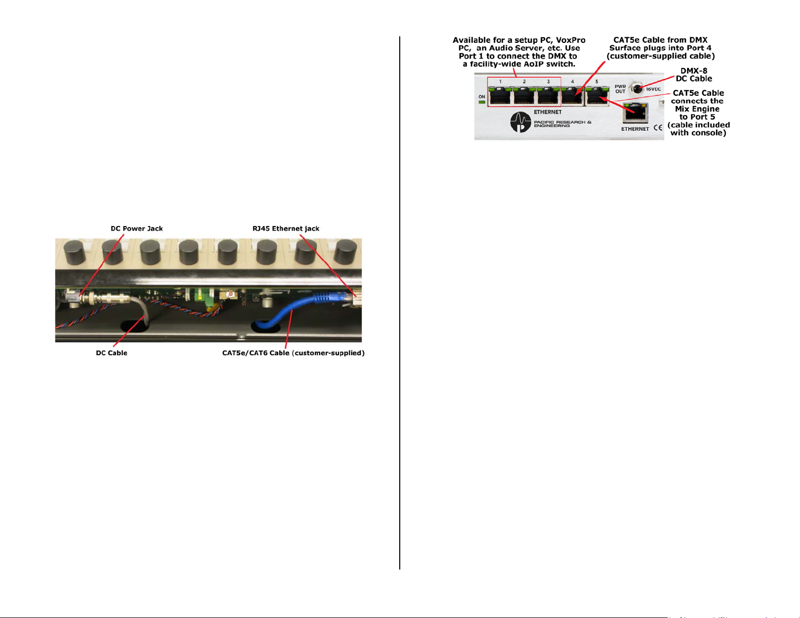
the Mix Engine (Figure 2-3). Plug the CAT5e cable into Port 4 on the builtin ETHERNET switch. On a DMX-8 Surface plug the DC cable into the
PWR OUT jack, tightening its housing on to the threaded jack .
On a DMX-16 Surface, route the CAT5e cable to the En gin e a nd plug it
into Port 4 on the ETHERNET switch. Plug the in-line DC power supply’s
IEC AC cord into an is ola ted AC outlet.
If not connected a lr eady, connect the shor t blu e CAT5 cable (supplied
with the console) from the ETHERNET jack to Port 5 on the ETHERNET
switch, as shown in Figure 2-3
Figure 2-3 Mix Engine, Rear Panel Partial View,
Ethernet and DC Power Connections
Fastening the Surface to the Countertop
If the Surface must be fastened to the countertop for security reasons,
the two front feet from the chassis must be removed. The Surface’s
control panel (identif ied in Figure 2-1) must also be r em ov ed. Two long #6
screws with oversize washers and lock washers are required. The screw
length must extend through the countertop, from below, and through the
two front feet with j ust enough thread left to fasten to the chassis. These
two screws must not extend over ¼” through the chassis when tight, to
avoid contacting th e c ontrol panel circuit board or ribbon c a ble.
The cable access hole must already have been drilled (per the steps
starting on page 10) and the two Surface cables must have been run
through the hole and plugged into the Surface. The Surface must be
unpowered during this procedure.
1. Unscrew the two front feet. Retain the two #6 s crews, lock
washers, and flat washers for possible future reuse.
2. Remove all of the hex head screws , us in g a 1/ 16” hex driver, from
around the control panel. Lift it up just enough to unplug the
ribbon cable(s): one cable on a DMX-8, tw o cables on a DMX-16.
Set the control pan e l a s ide.
3. Set the Surface into position and m ark the countertop through the
front two feet’s mounting holes using a pencil, the 1/16” hex
driver, or a thin center punc h.
4. Move the Surface aside and drill two 3/16” holes completely
through the cou ntertop.
5. This step requires two people. One person inserts and holds the
two long #6 screws (with lock washers and oversize washers)
through the cou ntertop from below (with the appropriate
screwdriver for the two screws).
A second person sets the two feet onto the screws then aligns the
Surface over the two scr ews , holding it in position while the two
long #6 screws are tightened. Make sure the Surface remains
11

parallel with the countertop edge while tightening the two screws.
Do not overly compres s the two rubber feet and verify the two
screws do not protrude over ¼” through the chassis.
6. Set the back edge of the control panel onto the Surface chassis
and plug in the ribbon cable(s). Set the control panel back down
onto the chassis and reinstall the hex-head screws.
PR&E MIX ENGINE CONNECTIONS
To facilitate wiring the PR&E Mix Engine, create a wire list, listing all
connections to and from peripheral devices. Identify and c r ea te labels for
each end of each audio, logic, and network cable. List these connections in
a master facility wiring logbook to ease ins ta llation, futu r e system wiring
and equipment changes, and sys tem troubleshooting.
Audio cabling to and from the Mix Engine should always be run with the
maximum practic a l d is tance from all AC mains wiring. The Surface’s power
cable only carries DC voltage, so audio wiring can r un parallel to or even
be tie wrapped with this c able without problem.
All line level ana log a udio, AES/EBU , and logic signals are on the Mix
Engine and use RJ45 jacks. Pin out signal lists, and the standard category
wire colors used for the analog and digital audio conn e c tor s and the Logic
connector are shown in Figure 2-4.
Figure 2-4 Audio & Logic RJ45 Pin Outs & Signals
For most applicat ions, either shielded twisted pair (STP) or unsh ield ed
twisted pair (UTP) wiring can be used interchangeably. When crimping
your own CAT5 cables, UTP has an advantage because it’s a lot easier to
crimp than STP w ir ing. To simplify au dio wiring, standard length straightthru CAT5 cables can be used along with RJ45 Au dio Adapters to connect
to peripheral devices.
StudioHub, and other vendors, have a wide variety of RJ45 Audio
Adapters, most of which a re car r ied by W heatstone and PR&E dealers . For
more information about what adapters are available, and about
StudioHub+ wiring practices , refer to the StudioHub adapter w eb pa ge:
http://www.studiohub.com/adapterdonglessplitterscouplers.php
To simplify logic wiring, various GPIO Interfaces for WheatNet-IP Logic
connectors are a vailable from Nota BotYet (
breaks out the six G PIO connections fr om the Mix Engine or Raz or RJ45
Logic jacks to screw terminals so that “old school” hardware-wired
peripherals, like warn ing lights and hot mic LEDs, can easily be c onnected.
When RJ45-to-audio and RJ45-to-logic adapters are used, generic premade straight-thru CAT5 cables, with RJ45 plugs on ea c h end, can be used
to quickly conne c t the Mix Engine an d Razor I/O Interfaces to the audio
and logic connections on peripheral devices.
When wiring directly from an RJ45 ja c k on the Mix Engine or Razor to
individual XLR, TRS, or other audio c onnectors, single-pair UTP (DataMax
5100 or similar) can be used to wire an AES or mono analog con nection.
Dual-pair UTP (DataMax 5200 or similar) can be used for wiring to stereo
connections when a single connec tor (like a D-Sub) is used on the
peripheral device.
When wiring to a stere o a nalog device with two connectors use two
single-pair UTP wires connected to a common RJ45 to clea nly connect the
two audio connector s. Alternately , when breaking out the two wire pairs
from a single CAT5 cable to go to two audio connectors, place shrink
tubing over each wire pair then shrink tube those and the end of the CAT5
jacket to create a reliable, and clean looking, connection.
The exception to the practice of using UTP cable is for the microphone
cables that plug into the f em ale XLR connectors on the Engine, Razor 16A,
and M4IP-USB. These must use s hielded analog wiring specifica lly
designed for low-level balanced signals. Room monitor outputs that
connect to self-powered monitor speakers ma y also need to use shielded
cable, with the shield termin a ted a t th e m on itor speaker end, sin c e there
is no shield conne c tion on the Mix Engine’s RJ45 jacks.
Note: The StudioHub+ wiring convention specifies pin 4 as DC
Ground to support POE (Power over Ethernet). The Mix Engine and
Razor RJ45 connectors do not tie pin 4
ground since neither product supports POE. Thus, a ground
connection can only be made at the peripheral device end. If the
peripheral device has an unbalanced input with a Tip-Sleeve or
RCA connector, an audio balun transformer (balanced:
unbalanced) or a signal matchbox must be used.
All Mix Engine analog line-level inputs and outputs are intended to
connect balanced +4 dBu signals using only the plus (+) and minus (-)
signals from the peripheral s to connect to the + a nd - terminals on the
RJ45 plugs (as listed in Figure 2-4).
Unbalanced device outputs can directly connect to DMX analog inputs
by connecting th e low (-) signal wires (p in 2, ORG, and/or pin 6 , GRN) to
GND on the unbalanced device. Connect the hot wire (the un ba lanced +
signal) to the WHT/ORG and/or WHT/GRN wires (terminals 1 and 3). Since
the unbalanced device will h a ve a very low output level—as compared to a
www.notabotyet.com). Each
(the blue CAT5 wire) to
12

balanced signal, use the PR&E Navigator Device > Sources tab to adjust
the input gain. Any DMX input can be increased by up to +18 dB.
When DMX analog outputs need to connect to unbalanced devices, a
matchbox or an audio balun transformer (balanced:unbalanced) must be
used. You can, alternately, connect the + wires (the WHT/ORG and/or
WHT/GRN wires on terminals 1 a nd 3) to the unbalanced device direc tly ,
but the ground wire from the unbalanced device must be broken out of the
wiring and connected to the Mix En g ine or Razor chassis in order to
connect it to ground. One way to do this would be to connect a small
spade lug and grou nd wire to the Phillips screw on a MIC XLR connector.
Note: On an output, do not ground the two low (-) signals (the
ORG and GRN wires on terminals 2 and 6) at the unbalanced
device in an attempt to connect an unbalanced device directly to a
Mix Engine or Razor output. This can cause phase issues and
crosstalk, and c ould lead to componen t failure since this effectively
shorts an activ e op a m p output to ground.
Ethernet Connections
Ethernet network wiring also uses RJ45 jacks but, because a PRE-IP
network is running at 1000Ba s e-T (1 Gigabit or 1 GB) for the most reliable
network operation only C AT5e or C AT6 cabling should be used.
For a short conn ection, like conne c ting the PR&E Mix Engine to Port 5
on the Etherne t switch (Figure 2-3 on page 11), CAT5 cable can be u s ed
but all longer cable runs must use either CAT5e or CAT6 cabling.
Ports 1, 2, and 3 on the five-port Gigabit Ethernet switch are available
to connect an “a d m in PC” with the PR&E ap plic ations installed on it. This
PC will not need to rem a in connected during normal use u nless PR&E
Navigator is used to control signal connections. Alternately , if a VoxPro or
other audio editor PC is networked with the DMX, the PR&E apps can be
installed on that PC (it would then b e termed the admin PC). The other
two switch ports are available to n etwork a WNIP-compatible media
server, and/or a Razor I/O Interface or an M4IP-USB Blade.
Port 1 can alternately connect the DMX to an AoIP switch to network
the DMX with additional DMX and EMX consoles, Razor I/O Interfaces ,
M4IP-USB Blades, and WNIP-compatible media severs to create a large
PRE-IP network. See Appendix A for details on PRE-IP networ k expansion.
DMX POWER UP
The PR&E Mix Engine, the Razor I/O Interfaces , and M4IP-USB Blades
do not have power switches since all are designed for continuous 24/7
operation. They are designed to work with AC mains supplying 90 - 240
VAC @ 50 or 60 Hz. For the most reliable operation, all DMX c omponents
should only plug into isolated ground circuits (orange outlets in the U SA)
which are on a UPS (Uninterruptible P ower Supply).
When AC power is first applied, it takes a b out 90 seconds for e a ch DMX
device to boot up, c onnect to the PRE -IP netw ork, and be ready for use. If
the DMX-16 Surface is powered up without being connected to its Mix
Engine, or if th e Mix Engine itself is not pow ered, the meter bridge level
displays’ peak LEDs will scan across all meters to visually ind ic ate the
Surface is not communica ting with its Mix Engine. Once the Sur face and
Mix Engine are properly con nected via Ethernet, the meters’ LEDs stop
scanning.
When power is fir st applied to the Mix Engine, the rear panel green O n
LED (next to the E thernet switch) ligh ts up first. This is f ollowed by the
green LEDs blinking on active Eth er net switch ports. N ote that the Surfa ce
Ethernet jack only blinks one LED s ince it communicates at 100Base-T.
The Mix Engine and Razor ports wil l have both green LEDs blinking since
they communicate at 1000Base-T. A networked PC will also only blink one
LED when its NIC does not support 1GB speeds.
The front panel LINK LED (Figure 2-5) lights up solid when th e Mix
Engine’s Eth ern e t jack is connected to p ort 5 of the Ethern et s witch. On a
stand-alone DMX, the oth er two front panel green LEDs: ROUTE MSTR
(Route Master) and CLOCK MSTR (Clock Master) also light up solid—after
about 90 seconds, indicating the Mix Engine is ready for use.
When a new DMX is networked with existing EMX and DMX consoles , the
new PR&E Mix Engine may not be designated as a master, thus its ROUTE
MSTR and CLOC K MSTR LEDs could both be off. This simply indicates
there’s other networked Mi x Engines in the PRE-IP network which are se t
as the Route Maste r or Clock Master. W ith multiple Mix Engines, one Mix
Engine is designated as the Rou te M a s ter w hile a second one is designated
as the Clock Master.
Figure 2-5 Engine Front Panel Status LEDs
If the red ERROR LED s hould light, it indica tes an error condit ion has
occurred in the Mix Engine. To r eset this error, first try rebooting the Mix
Engine using PR&E Navigator. If the red LED r ema ins lit, power cycle the
Mix Engine (un plug the AC cord from the Mix Engine, wait five seconds
then plug the AC cord back in) .
If the red Error LED lights u p a gain after it restarts it indicates a serious
fault in the Mix Engine which will require service. Contact Wheatstone
technical support for assistance. See Chapter 5 (page 58) for information
on obtaining service and support for your DMX console.
13

CHECKING OUT THE DMX FEATURES
With the Mix Engine and DMX Surface both powered up and connected
to the built-in Ethernet switch, on a stand-alone DMX all three green LEDs
on the Engine’s front panel (Figure 2-5 on page 13) will be lit. The Surface
should appear as shown in Figure 1-1 on page 5, but without any m ete r
displays since there’s no audio connected to the c onsole yet!
Note: Figure 4-2, on page 46, identifies each fader chann el control
and Figure 4-4, on page 49, identifies each monitor control.
On Fader Channel 3, with the channel turned off, rotate the Channel
Encoder. That channel’s display switches to show a list of source names
with one name h ighlighted (Figure 2-6). The name shown above the white
line (Blade01 in Figure 2-6) lists the name of the system device with that
highlighted source (Blade 01 is the default n a m e for the PR&E Mix Engine).
Rotate the channel 3 encoder until BL001S02 is highlighted as shown in
Figure 2-6. Press on c e on the channel encod er to select that signa l. This is
called “clicking” the encoder–just like clicking a PC m ouse button. The
highlighted signal is now connected to that fader channel and BL001S02 is
shown, in green, in the middle of the channel 3’s display (Figure 2-7).
Note that in the nor m al displays the spac e a bov e the white line is used
to show when cue, equalization, and dynamics are active on that channel.
When cue is active, CUE is shown in the middle of this area. Icons for the
High Pass and/or Low Pass Filters are shown wh en they’re active. EQ (for
Equalization) and DYN (for Dynamics) are shown when they’re active on a
channel. From the factory, mic processing is loaded into channels 1 and 2,
and is turned on, hence the EQ and DYN indications on those two fader
channels.
Figure 2-6 Selecting a Channel Source
Rotate the encoder clockw ise to move the highlighting down the
alphanumeric list of names. Rotate the en c oder c ounter-clockwise (CCW)
to move the highlighting up through the names. The names wrap to
present a continuous list. NoSource, which appears at the top of the list, is
a good way to identify when the names have wrapped around.
Every physical input on the DMX Engine has a signal name of up to eight
characters. The default names all start with BL, for Blade, followed by that
Blade’s ID number (1 is the default ID number for the PR&E Mix Engine).
The default names end with a signal number, like S02, to identify the
physical connection on the Mix Engine and optional Razor I/O Interface.
All DMX inputs are set for stereo—except for Analog Input 1, which is
set as dual mono, with BL01MIC1 and BL01MIC 2 set as its source names.
The remaining Analog inputs are: BL001S02; BL001S03; and BL001S04.
The four AES input s’ default names are BL001S05 thru BL001S08. These
numbers match the jack numbers listed on the Mix Engine’s rear panel.
Analog input 1 is design ed to jumper to MICS OUT so the two mic
preamps can be used without ha ving to change any settings. If the built-in
mic preamps are not used, Analog Input 1 can be reset to a stereo input
using PR&E Navigator
After the Mix Eng ine’s physical input signal names you’ll see the internal
signals within the DMX. Many, if n ot m ost, of these signa ls are typically
not set as “visible” on fader channels, but on a new console all signals are
set as visible to ease installing and configuring the DMX. Setting signal
visibility is cover ed in the Visibilities Page Tab section starting on page 29.
(see page 38, Changing the Signal Type section).
Figure 2-7 Displays for Channels 1, 2, and 3
Below the source name, in oran ge, is the channel’s mode setting. Th e
default setting for every channel is STEREO (mono sign a ls like mics are fed
to both left and right channels by default).
To either side of th e m ode name are icons to indicate source status. On
the right side a lock ic on indicates that source’s LIO status (logic control
status) by color when the channel is turned on. On the left side—if the
channel source is identified as a m ic , there’s a mic icon which turns red
while that channel is turned on.
Advanced Channel Features
Each channel has three Advanced Channel Features: Mode, Pan, and
EQ & Dynamics, which are accessed by “double-clicking” or quickly
pressing twice on the channel encoder. The advanced features are all
unlocked when the DMX ships from the f a c tory.
“Double-click” the channel 3 encoder (tap it twice quick ly). Mode now
appears above the white line. Rotating the encoder, while Mode is shown
in the display, ste ps through the four audio modes (Righ t, Left, Mono, and
Stereo). Make sure STER EO is s hown then double-click the encoder again.
Now Pan is shown above the white line. Rotating the encoder now pa ns
or balances the signal to the left or right of center. Readjust the encoder
so CENTER is shown then double-click the encoder again.
The displays on channels 1 -8 switch to show the EQ & Dynamics
control screens. The initial display screens set whether EQ & Dynamics are
turned on (set I n) or off (set Out) on that channel. Additional screens are
14
displayed to adjus t the EQ & Dynamic s settings. On fader channels 1 and
2, both EQ and Dynamics are set In by default, for “light mic processing,”
since these channels are typically assigned to the Host and Guest mics.
The rest of the fader ch annels do not have any EQ or Dynamics settings
applied. Refer to the Cha pter 4 s ec tion , EQ & Dynamics, starting on page
51, about how to: set EQ and Dynamics in/out; how to adjust their
settings; how to save the EQ & Dynamics settings on any channel; and
how to recall previ ously saved settings to any channel.
For now, double-click the channel encoder again. The eight channels
switch to their normal displays showin g their current source names.
Note: The Mode, Pan, and EQ & Dynamics controls should be
selectively locked out from board operator access pr ior to releasing
the console for daily use. This is done using the Talent Access page
tab in the DMX Surface S e t up
app (page 23).
Connecting Audio
To understand the audio connections and DMX Surface features, connect
a stereo analog audio signal (like a +4 dBu test tone or a CD player) to the
ANALOG 2 IN jack on the Mix Engine (Figure 2-9 on page 16 shows the
Mix Engine jacks) using wiring that follows the StudioHub+ wiring protocol
(Figure 2-4 on page 12). This audio input is named BL001S02, which was
set as the Channel 3 source in the previous section.
Assign channel 3 to PGM 1, PGM 2, PGM 3, and PGM 4 (light up all
four assignment buttons). Set the channel fader so the middle line on the
fader knob aligns with the two arrows at the -12 dB position. This sets that
channel for unity gain through the console.
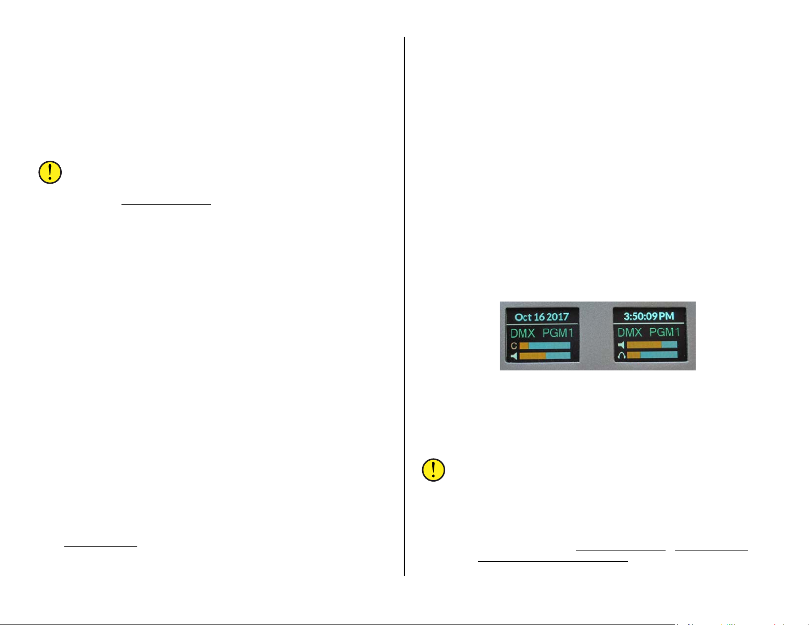
the CR Out jack. In the left column of the monitor section, select PGM 1
as the monitor source for the Control Room. DMX PGM1 is shown in the
left monitor disp la y (Figure 2-8). Use the CR encoder to adjust the
volume of CR Out. Its relative output level is indicated in the bottom bar
graph, with the sp ea ker icon, in the lef t m onitor display.
Move the test output to the HDPN Out jack. Its output level, and the
DMX Surface’s headphone jack level, is adjusted using the HDPN
encoder. Its level is indicated in the bot tom b a r g r aph in the righ t display
with the headphone icon. It uses the same monitor source as CR Out.
Move the test output to the STU Out jack. Its current monitor source is
shown in the right-hand display. NoSource appears in the right-hand
display from the factory. To set a source for the Studio, press/hold (for
three seconds) the EXT button just above the Studio encoder. The button
blinks and a list of source names appear in the right-hand display. Rotate
the Studio encoder to highlight DMX PGM1 then click th e Studio encoder
to assign that sour ce to the EXT button. The EXT button lights up solid and
DMX PGM1, now set as the Studio monitor source, is shown in the righ t
monitor display.
The Studio encoder is also used to adjust the STU Out volume, when not
selecting monit or s ources. The s tudio monitor level is indicated by the
upper bar graph in the right display with the speaker icon.
Turn Channel 3 on by pressing and releasing the On button directly
below that channel’s display. The button turns red indicating that
BL001S02 is now connected to the assigned Program buses.
If the input is a +4 dBu test tone, then all of the green meter segments
will light, along with the first y ellow segment, which indicates -20 dbFS
(dBFS = deciBels below Full Scale). This is equivalent to 0 VU on an analog
VU meter. The Program 1 and Program 2 meters should show this
level. The Switched meter will also show this level by press in g Meter
PGM 3 or Meter PGM 4 in the monitor s ection of the control s urface.
Connecting an analog test set to each of the four PGM ANALOG outpu ts
will confirm each is putting out +4 dBu. Connecting a digital test set to the
four PGM DIGIT AL outputs (they h av e the same signals as the four analog
jacks) will confirm each is putting out -20 dbFS. The default sources
connected to the PGM outp uts are the PGM 1 to PGM 4 buses, bu t an
alternate source can be connected to any of these four stereo-only outputs
using PR&E Navigator
To check how the four analog monitor outputs (the four OUT jacks) work
connect a test set or a powered mon itor speaker with a balanced input, to
’s Crosspoint grid to change their connection.
Figure 2-8 Monitor Displays Show the Monitor Output Levels
Move the test output to the CUE Out jack. Press Cue on channel 3 (it
lights and CUE is shown in the chann e l display) then use the Cue encoder
to adjust the cue v olume. The upper bar gra ph in the left display, with a C,
indicates the cue output level. Note that e ven though this is a “stereo”
output, the DMX cue system is a mono sum of the input signal.
By following the steps covered in th e Checking Out the DMX
Features section you should now have a good understanding of
how to connect audio into and out of the Mix Engine and how to
use the DMX Surface controls. The rest of this chapter goes over
more specific details about the audio and logic jacks on the Mix
Engine and Razor I/O Interface.
Chapter 3 (beginning on page 20) covers how to install and use
15
the supplied PR&E apps (DMX Surface Setup
the PR&E System Configuration Tool
configure the console for your specific application.
) to name the DMX signals and
, PR&E Navigator, and
PR&E MIX ENGINE SIGNAL NOTES
This section covers the PR&E Mix Engine connections and which PR&E
app is used to configure that signal or c onnection. Figure 2-9 details the
audio and logic jacks on the back of the Mix Engine.
either a logic outpu t (e.g., as an On Tally, Studio In Use tally, Start Pulse,
etc.) or as a logic input (e.g., for Channel On, Channel Off, Cue, etc.).
Each Blade (PR&E Mix Engine, Razor, and M4IP-USB) also has 128 Soft
LIO (SLIO) logic signals th at can be used with WNIP-compatible devices,
like talent stations and media servers, for bi-directional command and
control of the DMX cons ole over Ethern et. SLIO signals are also assigned
using PR&E Navigator
(starting on page 40) for details on assigning both LI O and SLIO logic.
as either an input or an output. See Assigning Logic
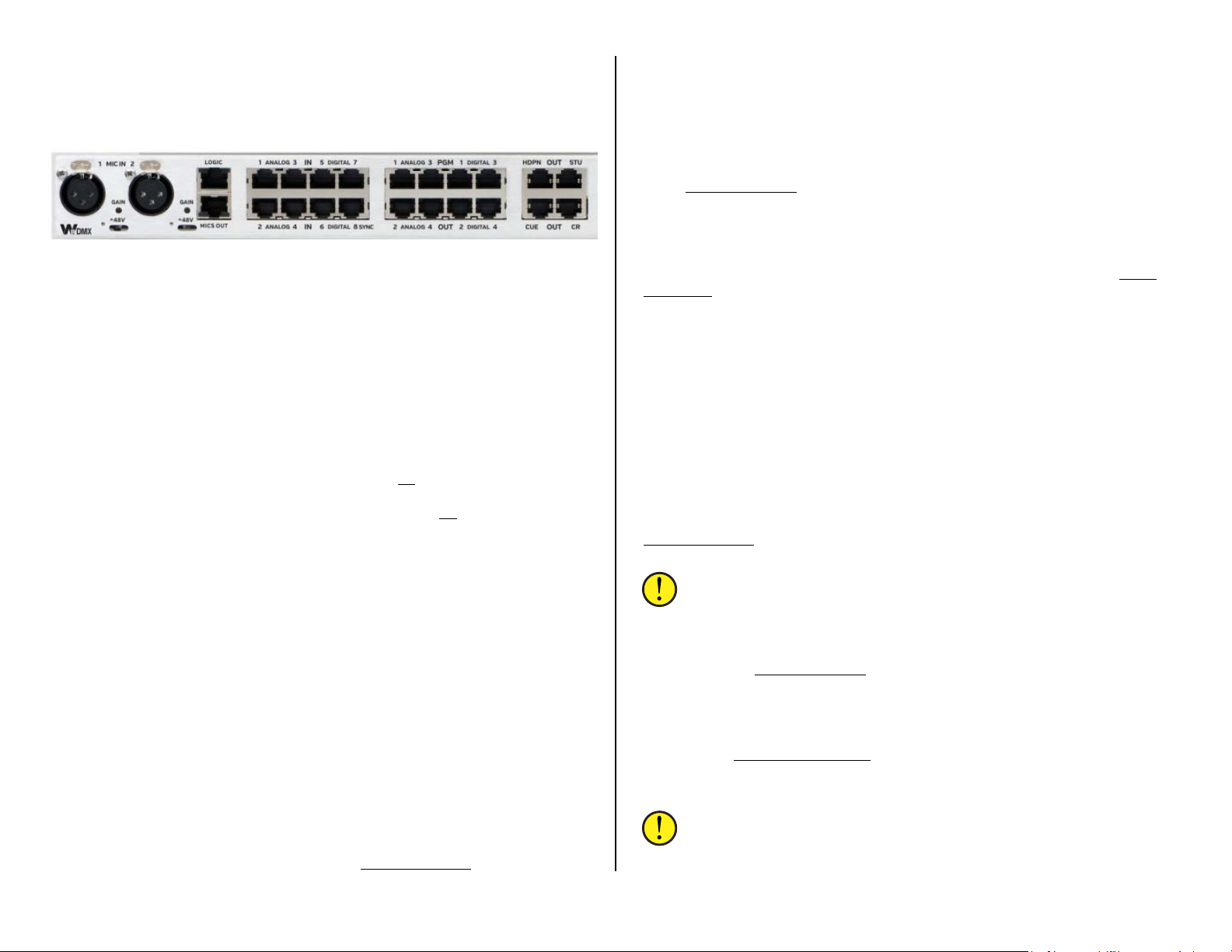
Figure 2-9 Mix Engine, rear panel, RJ45 Audio & Logic Jacks
Mic Preamps – There are two microphone preamps in the Mix Engine
with female XLR j a cks. One or two, dynamic or condens er, mics can be
plugged into these low-noise preamps in or d er to boost the mics up to line
level. The two mics are typically assigned to fader channels 1 and 2, which
have factory-set EQ and Dynamics Processing already applied, so having
to use external mic processors is not req uired with the DMX . If additional
mic preamps are needed, each Razor 16A I/O Interface has two mic
preamps and each M4IP-USB Blade has four SQ mic preamps along with
Vorsis mic processing, four USB ports, and local analog and AES outputs
for headphone and studio monitors or recor ding outputs.
Each Mix Engine preamp has an input trim control and a 48-volt
phantom power sw itch. Set the phantom switch on
mics. A yellow LE D lights to show phantom power is active. For dynamic
mics, like an RE-27, set the phantom power s witch to off (LED off).
The trim level, if it needs adjustment, is made after the console is wired
up since it requires the mic to be assigned to a fader chann el so its level
can be seen on th e meters and it can be listened to. Typically, the trim
level is adjusted with the channel fader set to un ity gain. With the talent
speaking at their normal “radio voice level” adjust the trim pot so the top
of their average bar graph signal is around -20 dB FSD or their peaks are
bouncing around -8 dB dBFS on the Program meters. If you want to add
EQ and Dynamics Processing, you would do so after the mic preamp gain
trim is properly adjusted.
MICS OUT – This jack has the line level outputs from both mic preamps:
Mic Preamp 1 is “left” and Mic Preamp 2 is “right.” Connect a short
straight-thru CAT5 cable from MICS OUT to ANALOG IN 1 since that
input is preset for two mono mic signa ls rather than for a stereo signal as
are all other Mix Engine inputs.
LOGIC - The Mix Engine and Razor I/ O Interfaces each have one RJ45
Logic jack for con necting logic to non-IP external devices like a Henry
warning light in ter face or a CD play er . Each Logic jack has six LIO logic
ports (on pins 2–7) plus ground (on pin 1) and +5 volts (on pin 8). Each
logic port is independently a s s ign ed, using PR&E Navigator
to power condenser
, to set it as
ANALOG IN - All analog inpu ts a r e des ign ed for balanced +4 dBu sign a ls,
but unbalanced -10 dBv signals can also be connected—without needing a
match box, since each input has input gain and balance controls in PR&E
Navigator (see Level & Balance Con tr ols on page 39).
Inputs are labeled as ANALOG IN 1-4 on the Mix Engine. They are
assigned these default names: BL01MIC1 (in put 1 left), BL01MIC2 (in put 1
right), BL001S02 (input 2), BL001S03 (input 3), a nd BL001S04 (input 4)
in the DMX signal lists. Inputs 2, 3, an d 4 can also be separated in to two
mono inputs (see Changing the Signal Type on page 38) to allow two
independent mono signals, like a pa ir of phone hybr ids, to c onnect to one
RJ45 jack.
DIGITAL IN – The four digital inputs are designe d for stereo differ ential
AES/EBU (AES3) signals which, in most cases, can alternately have an
unbalanced S/PDIF digital signal connected. These jacks are labeled as
DIGITAL IN 5–8 on the Mix Engine. Their def a ult names are BL001S05 –
BL001S08 in the signal list s . They have the same gain/balance controls in
PR&E Navigator
split into two mono signals for connecting digital phone systems.
Note: Digital In 8 can also be used as a Sync Ref er ence input to
synchronize the DMX to an external sample cloc k signal.
PGM OUTPUTS – There are eight PGM Outputs (f ou r stereo bala nced
analog and four AES/EBU) which, by default, connect to the PGM 1 – PGM
4 buses. In the PR&E Navigator
named CB01PGMA – CB01PGMD. A different source can be conn ec ted to
any of these destinations but note th at these outputs cannot be split for
dual mono out operation and the same signal is appli e d to both the analog
and AES/EBU outputs. If you change the source on any PGM output,
uncheck the DMX S ur fa ce Se tup
(Input/Output on page 23) since that option reconnects the four PGM
buses to the four PGM outputs if the Mix Engine is rebooted or powered.
Note: The four AES/EBU outputs can only connect to balanced
AES/EBU inpu ts. Connecting them to unbalanced S/PDIF inputs will
not work. A signa l tr a nslator is required.
as the analog signals and any AES/EBU input can also be
Crosspoint Gr id these four destinations are
option Use Def a ult Signal Mapping
16

MONITOR OUTPUTS – The default sources connected to the four stereo
analog outputs (CUE, CR, STU, HDPN) are: DMX CUE; DMX CR; DMX Stu;
and DMXHdpn. Normally the four monitor level controls (CUE, CR,
STUDIO, and HDPN) control the levels of these monitor outpu ts (their
default destina tion names are: CB01CUE; CB01CR; CB01STU; and
CB01HDPN in the PR&E Navigator
source is connected the Surface control no lon g er affects that output. If
any alternate source is connected be sure to uncheck Use Default Signal
Mapping in the DMX Surface Setup
CR OUT is normally connected to powered Control Room monitor
speakers, while CUE OUT is normally conn ec te d to one or two powered
cue speakers, so they a r e not often connected to an alternate source. If
there is no associated talk studio, the STU OUT jack could connect to a
hybrid and call recorder, an air skimmer, an internet streamer, or oth er
device. Likewise, the HDPN OUT jack, if it doesn’t need to connect to an
outboard headphone amp, could connect to an alternate source for
another stereo analog line output from the Mix Engine.
Note: The built-in ¼” headphone jack, on the right side of
Surface, is destination DMXH d pn, so it is not affected if the HDPN
OUT jack on the Mix Engine is connected to an alternate source.
Crosspoint grid). But when an alternate
app to maintain tha t new source.
ADDITIONAL DMX FEATURES
This section covers other DMX Surface operational features including
how to use the PGM 4 assignment buttons as Off Line bus select buttons
and how to assign sources to the user-set buttons in the monitor control
section. Other topics covered include: gain trim and balance control on the
inputs and outputs; setting mic and monitor muting; and using Telco
devices with the DMX console.
Callers & Remotes
Callers and remotes are commonly called Telco devices since each has a
From Network audio signal (the audio from the caller or remote) and a To
Network audio sign al (called the mix-minus signal) which is sent back to
the Telco device so the caller / rem ote can hear the board operator or hear
the on-air signal—but always minus their own From Network audio.
The To Network audio s ig nal is typically derived from the Telco channel’ s
bus-minus signal which is manually connected to th e hybrid or codec using
the crosspoint grid in PR&E Navigator
Associated Conn ections (each method is cov er ed in Chapter 3).
When using callers and remotes on the DMX, the PGM 4 bus assign
buttons serve double-duty as Off Line (OL) bus assign buttons. The Off
Line bus is solely used to create the To Network signal for a ph one caller
or remote while they are not on-air (i.e., their channel is turn ed off). When
the board operator and/or producer’s mics are assigned to PGM 4/OL
(which is also typically set for p r e -sw itch and pre-fader operation), the
talent can carry on a hands-free conversation with the calle r or r e mote.
or automatically connected by using
When the caller or r emote goes live, the To Network signal is the busminus of the air s ignal (typically PGM 1) so that the caller/remote hears
everything else going to air, but always min us their own audio.
Selecting a Telco device as the channel source is what triggers the builtin Auto Fold Back feature which automatically toggles the To Networ k
signal between the OL bus ( used when the channel is off) and the on-air
PGM bus (used while their channel is turned on). This feature allows a
caller or remote to go liv e to air without the boa rd operator ha ving to
change any board settings . If the board operator n eeds to talk to the caller
or remote while they’re live, pressing the TB button override s the PGM
bus-minus audio sending their mic to that caller or remote.
When a caller or a remote is assigned to a dedicated f a der c hannel,
setting up their To Network signal is simple: that fader channel’s busminus signal is connected (typically using PR&E Navigator
Grid) to the phone hybrid or codec outpu t from the Mix E ngine or Razor.
When callers (or m or e likely remotes) ar e set visible on mu ltiple fader
channels things g et m ore complicate d s ince their mix-minus signal, which
is derived from the bus-minus signal of the channel the caller or remote is
on, also has to be changed to be from whatever channel they are on .
Fortunately, the PR&E Navigator
“trigger conditi on” to be set up for the s ystem to monitor: like a codec
being dialed up on fader cha nnel 15. When that trig ger condition is
detected the system responds by connecting, in this example, the fader 15
bus-minus signal to that codec’s output.
Typically, an Associated Connection would be setup for each fader that a
codec is visible on so that no matter which channel the code c gets taken
on, the correct bus-minus signal will always be connected back to that
codec. Setting up Associated Conne c tions is covered in the Creating and
Using Associate Connections section on page 41.
Associated Connections feature allows a
’s Crosspoint
Using the Off Line Bus
Because the DMX Surface does not have dedicated Off Line bus
assignment buttons, the PGM 4 bus assign buttons can be setup to
function as Off Line assign buttons using the DMX Surface Setup
the PGM 4 / Off Line Options section on page 26).
When this is done, the board operator mic channel is assigned to the OL
bus (its PGM 4 button is lit). When the caller/remote ch annel is off, and
assigned to cue, the board operator can hear th e caller/r em ote in the cue
speakers (or their headphon es ) and th e c aller/remote can hear the talent
using their mic, to a llow for a hands-free conversation.
If a Host or call screener also need to talk to the caller/remote then their
mic channels would also be assigned to PGM 4. They would then talk to
the caller using their mics an d hear the caller through the c ue speaker.
app (see
17

Telco Device Connections
Each caller/remote device’s From Network signal typically con nects to a
Razor analog or digital input with two devices sharing a common RJ45 jack
input, which is s e t for two mono signals ra ther than one ster e o s ignal.
A Razor mono analog or digital output is then connected to the To
Network input on the caller/remot e de vice. The caller/remote output is
connected, in PR&E Navigator
for the channel that the caller/remote is using. See the note on the next
page regarding mono vs. stereo signals on Razor I/O Interfaces.
’s Crosspoint grid, to the bus-minus signal
Signal Gain & Balance Adjustments
PR&E Navigator has level controls for every ph ysical input an d output on
the Mix Engine and Razor (see Level & Balance Controls on page 39). Up
to 18 dB of gain, or 18 dB of trim, from unity gain (0 dB), can be applied
in real time to the audio. Viewing and adjusting the level controls for the
inputs is done in the Blade > Sources tab for each Blade. The outputs are
viewed and adjusted in the Blade > Destinations tab for each Blade.
Monitor Muting & Hot Mic Logic
Although any signal can be set to mute th e monitor outpu ts , typically
only mics are set to mute outputs. For Control Room mics you’ll want to
mute the CR and CU E outputs, unless C ue only feeds the studio, in which
case the Studio mics would be s et to m ute the STU and CUE outputs.
These settings are made usin g the DMX Surface Setup
tab (details on using the VDips Page Ta b is on page 25).
app’s VDips page
Setting Monitor & Meter Button Sourc es
The DMX Surface’s monitor section, at the right end of the S urface, has
two columns of controls (see Figure 4-4, page 49). The lef t c olumn (CR)
has the meter and Control Room monitor controls ; the right column
(Studio) has the Events, Timer, and Studio monitor controls. There are
also four user-set source selectors (Meter EXT, CR EXT 1 and EXT 2, and
Studio EXT) plus a user-set Soft button which can be assigned for a
number of different functions, from simple (being set as a talk-to-producer
button or as a remote door lock/unlock button) to complex (taking a salvo
to setup certain channels for a specific function like voice tra cking).
To assign a source to the Meter EXT, or to the CR Monitor EXT 1 or
EXT 2 buttons, press/hold that button for thr ee s econds (until the b utton
begins to blink). The left monitor dis play switches t o s how the source
names available to be assigned to th a t button. Highlight the desired n a m e
using the Cue/Source en c oder a nd then click the encoder to ass ign the
highlighted sourc e to that button.
Two sources can be assigned to the Studi o E XT button: one is selected
when lit and the other is selected when it’s unlit. Press/hold the unlit EXT
button, until it bl inks, to set the unlit button source . Press/hold the lit EXT
button, until it bl inks, to set the li t button source. I n e a c h case the right
monitor display switches to show the available source names that can be
assigned. Use the Studio encoder to highlight a sou r ce name then click the
Studio encoder to a s sign that source.
You can also select a s tudio monitor “ on-the-fly” source by press/holding
the studio encoder, for about three second s , until the list of visible source
names appears in the right-hand monitor display. Highlighted the desired
source then click the Studio encoder. The selec ted source is th e n shown in
red in the right monitor display.
The list of source names that can be assigned to the EXT buttons is set
using the DMX Surface Setup
app’s Visibilities page t a b (page 29).
Saving and Taking Events
The four Event buttons (Event 1 – Event 4) are used to both save and
take console events. A console “Sa ve Event” saves the current settings for
all fader channels (including the Advanced Channel Feature settings) along
with the monitor panel sources and user-set button settings. Typica lly,
engineering sav es the four events a nd then locks out the s ave function
from further us e s o that board operators c an only take eve nts.
To save an Event after the console is se tup for a specific s how or
daypart: press/hold the Event button you want to update. After about
three seconds the button begins blinking. Continue holding the button for
another couple seconds, until the button is lit solid, which indicates the
current status of every Surface control is now saved to that Event number.
Note the event number, an d its console fun c tion or day part, and relay
that information to the board operators.
To take an Event press/hold an Event button until it begins to blink th e n
release the button. Tapping the blinking button then takes that event,
updating the DMX Surface settings. That Event button then is lit solid to
indicate it’s currently active.
Once the desired Events are saved use th e DMX Surface Setup app’s
Talent Access page tab (page 23) to lock out the board operat ors from
overwriting the saved eve nts by unchecking Allow Save Events.
Programming the Soft Button
The Soft button in the CR column in monitor controls can be assigned to:
take a salvo (to make multiple system con nections simu lta neously); make
a momentary connection (useful for talking to an external destination); be
an indicator, to show the hotline phone is ringing; or control a logic output
with button illumin ation (like a Dump button for a profanity delay unit with
the LED functioning as a safe indicator).
How the Soft button functions: as a tally only; as a toggle switch; or as
a momentary switch, is sent in the Buttons pa g e ta b in the DMX Surface
Setup app (page 28). What the button controls, and how the button’s LED
is controlled, is se t in the PR&E Navigator
starts on page 40).
18
app (the Assigning Logic section

RAZOR I/O INTERFACE NOTES
Each Razor has eighteen RJ45 connectors: eigh t have the audio in puts;
eight have the audio outputs; one h a s the Logic LIO; and one (Ethernet)
connects the Ra zor to a PR&E Mix Engin e Ethernet switch port or to a
facility AoIP s witch in a larger PRE-IP network.
On a Razor 16A, sixteen RJ45 connectors are used for the analog inputs
and outputs, each carrying two analog signals (stereo or dual mono). The
Razor 16A also ha s two built-in mic prea m ps, like the PR&E Mix Engine, so
it also has two fema le XLR Mic Inputs and one Mics Out RJ45 jack, which
is connected to an Analog Input usin g a short CAT5 patch cor d . That input
would then need to be split into two mono inp uts from its default stereo
setting using the PR&E Navigator
for details on splitting a stereo input or output into dual mono signals) .
On the Razor 16D, the sixteen RJ45 inputs and outputs each carry one
stereo AES/EB U signal. Any input or output can also be spli t into two mono
signals in PR&E Navigator (page 38, Changing Signal Type).
On the Razor 16AD (rear p anel shown in Figure 2-10) the first four
RJ45 jacks (IN 1–4) are stereo analog inputs. The remain ing four RJ45 IN
jacks (IN 5–8) have four stereo AES/EBU inputs. T he first four RJ45 O U T
jacks have the analog outputs (OUT 1–4) while the last four RJ45 jacks
(OUT 5–8) have the stereo AES/EBU signals.
(see Changing Signal Type on page 38
screen shows the levels for that Razor’s inputs. A second screen shows the
eight stereo output levels. The othe r two screens show tec hnical details for
that Razor like its system name, IP address, MAC address, and version of
code that’s run ning on that Razor.
Figure 2-10 Razor 16AD rear panel connections
Note: The Razor’s Ethernet A oIP jack has eight paired incoming
and eight paired outgoing audio streams. When a Razor input or
output is split into tw o mono signals , each mono signal consumes
one of the eight aud io s tr eams going into or out of the Razor . This
means that if f our stereo inputs or outputs are split in to eig ht
mono signals, and all of those mono sign a ls are connected in PR&E
Navigator, the remaining four stereo inputs or outputs cannot be
used simultaneously because all eight audio streams would already
be consumed by the eight mono sign a ls .
LOGIC - The RJ45 Logic connector is used to connect hard-wired logic to
external devices like warning light interfaces an d tallies. Each Logic
connector is wired per Figur e 2-4 on page 12. The logic conn ec tion s a r e
configured using PR&E Navigator
assigned logic function (see Assigning Logic on page 40).
FRONT PANEL DISPLAY & CONTROL - The Razor has a front panel
OLED display and a rotary encoder (Figure 2-11). The encoder is used to
step through the four scr eens that can be displayed on the Razor. One
as either a logic input or output with an
Figure 2-11 Razor front panel OLED and Encoder
19

3 – PR&E APPS AND CONSOLE CONFIGURATION
T
he DMX console’s factory-default configuration settings
allow it to be powered u p a nd used straight out of the box.
To set up the console for your specific application the
default configur a tion settings are edited using the software
apps included on a USB flash drive that ships with the console. The apps
can also be downloaded from a Wheatstone file download site (con tact
Wheatstone Tech Support for the links).
The PR&E software apps are installed on an admin PC running Windows
10, 8, 7, or even XP sp3. To communicate with the Mix Engine and DMX
Surface, this admin PC must be set for a fixed IP address in the
192.168.87.0 subnet. Even though the DMX can be changed to use
another Class C subnet, we recommend leaving the DMX set to the default
192.168.87.0 subnet.
Before setting the IP on the NIC connected to the DMX, c onnect the
admin PC to Port 1, 2, or 3 on the Mix Engine’s built-in Ethernet switch
(see Figure 2-3, page 11). T hen set the admin PC to 192.168.87.21 with
a subnet mask of 255.255.255.0. This puts it on the same subnet as the
PR&E Mix Engine (IP address = 192.168.87.101 & name = Blade01) and
the DMX Surface (IP address = 192.168.87.201 & name = Surf01).
set to the recommended settings. If the NIC was incorrectly assigned,
close the DMX Surface Setup
Panel to correct the s e ttings, then restart the DMX Surface Setup
Figure 3-1 DMX Surface Setup, Default View
app then use the adm in PC’s Network Control
app.
To insure each PR&E app is properly installed right-click on the ins ta lle r
icon, or on its file name, and select “Run as Administrator.” Accept the
default installation settings. If a previous ver sion was installed, the
installer automa tically uninsta lls that version prior to in s talling the new
version. A shortcut icon is added to the desktop. In the Sta r t m enu, the
three PR&E apps can be found in the Wheatstone PR&E folder.
DMX SURFACE SETUP APP
The DMX Surface Setup app is one of the main apps used to
configure the DMX console (the other being PR&E Navigator)
Double-click its desktop icon, shown at right. The app opens
showing the Device Properties tab (Figure 3-1). Click on th e
Locator tab to show it (Figure 3-2). The Locator tab lists every
DMX device connected to the Mix Engine’s Ethernet switch. For a
new DMX console only two dev ices will be shown: the Mix Engine and the
DMX Surface. (Figure 3-2 also shows that the admin PC has the WNIP
audio driver installed to play and record AoIP audio.)
If no devices are shown, confirm the admin PC, Mix Engine, and Surface
are all plugged into the Ether net switch. Make sure the admin PC’s NIC is
.
Figure 3-2 DMX Surface Setup, Locator Tab View
20
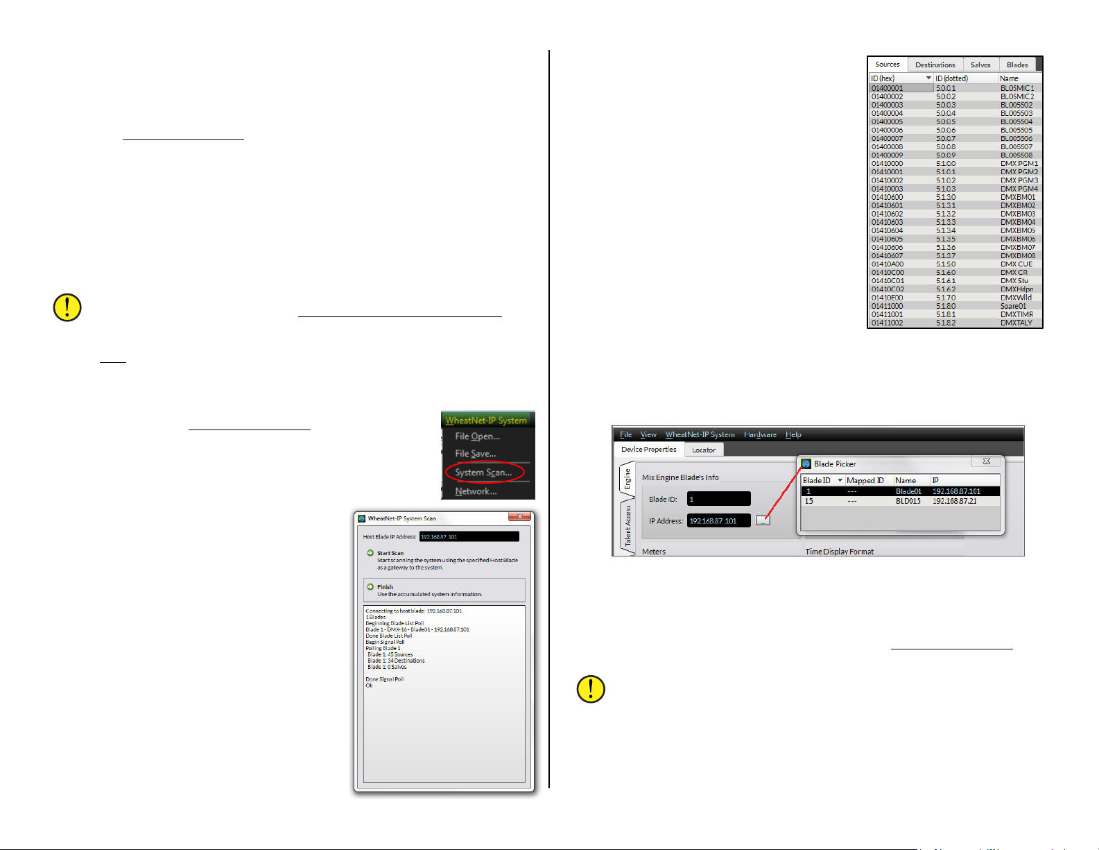
If you still have no devices listed verify that the correct IP address is
shown above the Select NIC… button. If the app is using the wrong NIC,
click Select NIC… to open the Network Setup window. Click Set Nic… to
view the NICs on the admin PC. Select the correc t N IC then click Okay
twice to close the window. If the NIC is changed you must close and
reopen the DMX Surface Setup
To refresh the Loc ator’s list of devices, click Refresh. This clears the list
and re-queries the network to dis play detected devices.
Clicking on a device row in the Locator pane (as shown in Figure 3-2 on
page 20) shows the details for that devic e in the Set Selected Device
Properties pane below the Locator. This is where the default settings for
any device can be manually edited by advanced users who wish to use a
different subnet and a s s ign their own IP addresses for networking multiple
DMX consoles toge ther.
Note: When multiple DMX consoles and Razor I/O Interfaces will
be networked together use the PR&E System Configuration Tool
(see page 42) to automatically change their settin gs rather than
manually editing their entries in the Device Properties pane. The
Tool
is used with new DMX consoles and Razors to change their
factory default settings to simplify adding additiona l devices.
app.
Selecting the Mix Engine & Surface
Up to this point the DMX Surface Setup app is simply
showing the PRE-IP devices it’s detected on the network.
To configure the DMX Surface we must first scan the
system and then set the Mix Engine as the Host for the
DMX Surface. The first step is to click the menu item:
WheatNet-IP System and select System Scan
to open the System Scan window.
The Host Blade IP Address should show
192.168.87.101 (the IP address of the PR&E
Mix Engine on a new DMX console). If no
address is shown, manually enter that IP
address into the entry box.
Click on Start Scan and the app now
queries that Blade (the gen er ic network
identity for a PR&E Mix Engine) and shows
various message s in the log window. Once
Finish appears click on it to c los e the
window. A “sav e sy s te m info?” dialog pops
up. Click Yes to save the system information.
A Save File dialog box opens showing the
default save loca tion. Click Save then Yes to
save the sysinfo.wnsi3 data file, which
saves your system inf or m ation to the PC.
The System Info pane, at the right side of
the app window, will now be populated with
Source names, as shown at right. C lick on
the other tabs: Destinations; Salvos; and
Blades, to show the scanned Destination
names; that no Salvos have been created
yet; and that the PR&E Mix Engine is Blade
ID 1 with the default name of Blade01.
Click on the Device Properties tab to
show that tab. It has six page tabs
(Engine, Talent Access, VDips, Monitor
Config, Buttons, and Visibilities) along the
left side of the tab (Figure 3-1 on page 20).
The page tabs allow various DMX
parameters to be viewed and edited to
configure the DMX Surface. Click on each
page tab to see what each has to offer then
reselect the Engine page tab.
Each page tab is separated into sections listing similar pa r ameters. In
the Mix Engine Blade’s Info section (Figure 3-3) click the Picker icon (the
small rectangular icon) to open the Blade Picker, which lists the detected
blades. Double-click the Blade01 row to select it. This closes the Picker
and transfers the Blade ID and IP address into the two entry boxes.
Figure 3-3 Selecting the DMX Engine in the Surface Setup App
This action sets that DMX Mix Engine as the “host” for your DMX
Surface. Next, the DMX Surface that’s being hosted by this Mix Engine
must be selected so that th e app can communicate directly w ith it. This is
done using the Devices pane at the bott om of the DMX Surface Setup
app’s window. When first using the app, this pane will be empty.
Note: If this pane is not shown, select the menu item View then
check Devices to display the Devices pane, as shown at the bottom
of Figure 3-1 on page 20.
Click the Add button to op e n the Add Device dialog box (Figure 3-4 on
page 22). In the Add Device window c lick Locate… to open the Locate
window. If Surf01 is not listed, click Rescan. Once Surf01 is shown, click
on its name to highlight it then click OK. The new DMX Surface name
21

(Surf01) and its IP address (192.168.87.201) are then entered into the
Add Device dialog box (the Device Type is automatically set as DMX).
Click OK to transfer the settings t o the View Devices pane.
To now connect to that DMX Surface, click on its row to highlight it then
click the small square next to Remove (“x” the box). This instructs the
admin PC to now contact that Surface. When Surf01 Connected appears
in the lower right cor ner (as shown in the bottom half of F igure 3-4), the
admin PC is now com m unicating with the DMX Surface. Its current settings
are then shown in the DMX Surface setup
app.
Figure 3-4 Selecting the DMX Surface in the DMX Setup App
Now that the admin PC is communicating with the Mix Engine and the
Surface, it’s time to use the DMX Surface Setup
console for your specific application.
Note: Several settings, like editing the console’s default signal
names, setting signal formats, a nd assigning logic, are done using
the PR&E Navigator
app (its description starts on page 31).
app to configure the DMX
Figure 3-5 Apply Changes Warning Pop-Up
Note: We recommend that you do not check Do not show this
warning again during this session. When it’s checked, if you switch
to a new page tab, and there were any pending changes on the
previous page tab, those pending changes are discarded.
Engine Page Tab
The Engine page tab has eight sections: Mix Engine Blade’s Info
(covered in the last s e c tion), Meters, M a chine Logic, Input/Output, On-Air
Tallies, Display Brightness, Time Display Format, and Source Select. These
settings affect the overall operation of the DMX Surface.
If, at any time in the f uture, you’ll network multiple consoles and
Razors together, we recommend that y ou use the PR&E System
Configuration Tool (page 42) to change the console from using its
factory default settings. Doin g this now will mak e it e a s ie r to a dd a
new console or Ra zor in the future since their factory default
settings will not be in conflict with any device already in your PREIP network.
Appendix A also has details about creating a PRE-IP AoIP network.
Device Properties Page Tabs
The DMX Surface Setup page tabs are divided into sections to group
similar configu r a tion settings. When changes are made on a page tab they
are all “pending” until the Device Properties tab Apply button is clicked to
send the changes to the DMX Surface.
If a different page tab is selected, after you’ve made changes but Apply
was not clicked, a pop-up warning (Figure 3-5) appears. Clicking Yes
applies the changes. Clicking No discards all changes made on the
previous tab sinc e the last time Apply was clicked.
Figure 3-6 Engine Page Tab
Meters
When Switched Meter Auto Cue is checked (the box has an x) the cue
bus level appears in the s witched meter while cue is active. This overrides
the source set by the Meter buttons. When unchecked, the default setting,
cue does not affect the switc hed meter display.
The Mode: setting affects all three meters. Peak and Average is the
default setting, but the meters can alternately show Average Only or Peak
only for special applications.
22

The Average signal level is shown using a bar graph display while the
Peak level is shown using one L ED per channel, to indicate the highest
instantaneous audio levels, which are typically 6 – 12 dB above the top of
the average level bar graph. Note that the Peak decay time is fixed.
The AutoDim Level settin g is used with th e AutoDim Timeout entry.
When the AutoDim Timeout is reached the OLED displays dim to the
assigned Dim level setting. If the AutoDim level is set to 1 the displays are
basically turned off. The default entry is 4 for this setting.
Machine Logic
This sets whether there is a logic output (either a tally or a start/stop
pulse) when remote channel on/off commands are received. When No LIO
with RMT is unchecked, the default setting, tally or rem ote start/stop
commands are sent out with remote channel on/off commands. When this
option is checked, no tally or remote start/stop command is sent when the
channel is remote ly turned on or off.
Input/Output
When Use Default Signal Mapping is checked the console’s default
monitor and program output connections are automatically recon nected
and locked whenever the Mix Engine or Surface are rebooted or power
cycled.
Note: Uncheck this option w hen any monitor or program output is
changed from th e ir de fault setting, otherwise the defa ult monitor
and/or program sources will autom atically be rec onnected in place
of those alternate c onnections when the Mix Engine or Surface is
rebooted or power cycled.
On-Air Tallies
The four on-air tallies (1 – 4) are usually all check ed even though,
typically, only Tally 1 and Tally 2 ar e used to provide hot mic warning
tallies for the Control Room and a S tudio. Tally 3 and Tally 4 can be used
to trigger hot mic warning lights in two ex te r nal locations like an announce
booth, a newsroom, or a sports bullpen. The tallies are triggered when the
logic function : Studio 1 In-Use up to Studio 4 In-Use is assigned as the
logic output comma nd on an LIO or SLIO.
The AutoDim Timeout en try sets how many minutes, from one to 59,
must pass after a Surface control w a s last touched before switching the
OLED displays fr om the Normal Level to the AutoDim Level. The default
setting is 2, which means that after no Surface control has been touched
for two minutes, the OLED displays dim dow n to the AutoDim Level.
Touching any c ontrol immediately returns the dimmed OL ED brightness to
the Normal Level.
Setting the timeout to 0 defeats dimming and the Normal Level setting is
used all of the time. Although this is OK for console configuration, we
recommend setting the AutoDim Timeou t to between 2 and 10 minutes
and setting the AutoDim Level so the dim m ed displays still s how a dim
image (settings of 2–4).
Time Display Format
The right monitor dis play shows the time-of-day in standa r d USA 12
hour format (AM/PM) or using military/ European forma t (24 hours). The
left monitor disp la y shows the date as month day year.
The date and time are set using P R&E Navigator (see page 33 Info Tab
for details). Until this is done, the date will show a de fault date starting in
the year 2000. The date is always shown as Month Day Year.
Note: The date and time must be reset, using PR&E Navigator,
each time the DMX is power cyc led.
Source Select
The default selec tion is Source Names. When the encoders are used to
select a new source, all visible source names are listed alphanumerically
with the host Bla de name shown in the dis p la y for each sour ce.
Display Brightness
These three parameters co ntrol the OLED displays’ brightness levels.
The Normal Level setting sets the brightness of the OLED display s from 16,
the maximum OLED brightness, to 1, which is virtually off. Becau s e OLED
displays will burn-in after displaying the sam e gr a phic over a long period
of time—and will als o g r a dually dim over tim e , we do not recommend
setting a new c onsole to a Normal Level of 16. The default level is 11, bu t
you’ll want to use the lowest settin g that still yields a n easy-to-read
display. In prod uction rooms with very low lighting t his might mean a
setting of 6 matches the ambient lighting in the s tudio.
To see the new setting reflected in th e O LED display brightness, c lick
Apply to transmit the updated setting to the Surfac e .
When Location Names is selected, r otating the channel encoder first
shows a list of Blade names. Clicking a Blade name then shows all of the
visible sources from that Blade. To view signals on a nother Blade, click
<< locations to step ba c k to the Blade list so another device c an be
selected. Needless to say most users leave Source Names selected.
Talent Access Page Tab
This page tab (shown in Figure 3-7 on page 24) has four sections:
Events; Bus Assignments; Channel Features; and Timeout to set board
operator access to various DMX Surface controls.
A fifth section: EQ allows the current EQ and Dynamics settings on any
channel to be saved to an “EQ configuration file” and a previously -saved
EQ configuration file to be loaded into any channe l.
23

Figure 3-7 Talent Access Page Tab
During console
If the DMX Surface Setup app is installed on a PC in the air
sounding “very strange” or even being severely distorted.
configuration the
section settings are
typically all left
checked, except for the
Timeout entry. When
it’s unchecked the
Advanced Channel
Features do not au totimeout, which makes
setting up the channel
EQ and Dynamics a lot
easier.
It’s important to
selectively limit access
to some features prior
to releasing the console
for daily operations.
Typically, Allow EQ & Dynamics is unchecked on air consoles once these
are set on the channels since, in the wrong hands, having access to these
controls could result in one or more channels suddenly having very
“strange sounding” audio!
Allow Save Events is also typically unchecked once the four console
events have been saved during con figuration.
Timeout Enabled would also be checked again so that any enabled
Advanced Channel Features (like Mode and P a nning) will timeout (return
to normal display) after no Surface control has been touched for twenty
seconds.
Events
These two settings control access to the four Event button s in the
monitor section of the DMX Surface. The Event buttons are used to save,
for later recall, four console setups. The current monitor set tings, current
channel sources, channel button settings, and Advanced Channel Feature
settings are all saved to allow your four most-commonly-used board
setups to be recalled at the touc h of an Event button .
For example: Event 1 could be used to recall the console settings for a
morning show with multiple mics and a remote traffic service; Event 2
could setup the con s ole for a single board operator; Event 3 could set up
the console for a regularly scheduled live remo te; an d Event 4 could set
up the Surface for overnight or una tten ded opera tion.
When Allow Save Events is checked, anyone can save an Event—which
will overwrite any previously saved Event. When unchecked, the Event
Save function is not active. This selection is typically unchecked once the
four Events are set up and saved during console configuration.
When Allow Take Events is checked, the board opera tor can take Events.
When unchecked the four Event buttons have no function. If Allow Tak e
Events is unchecked then Allow Save Events should also be unchecked.
Bus Assignments
These four selections set whether the board operator can change the
PGM assignment bu t ton settings across all of the console c hannels. For
most application s all four buttons a r e checked which allows the board
operators to change any assignment button setting as required.
Unchecking one or more Allow PGM Bus Assign selections (and then
pressing Apply) means the PGM button settings currently set on the
console cannot be changed by the board operators. This might be done for
consoles that serve dual-purposes, like simultaneous on-air and network
origination. The PGM buttons would be pre-assigned for the correct
operational mode and then would be unchec ked here to prevent board
operators from changing one or more PGM bus assignment settings.
Channel Features
This section sets wh ether any of the Advanced Channel Features are
accessible by the board operators.
Allow Mode, when checked, allows a fader channel’s audio mode to be
changed from Ster e o ( the default setting) to Left only, Right only, or Mono
sum. When unchecked, this feature is locked out from board operator use.
Allow Panning, when checked, allows le ft-right panning control of the
audio signal on th at fader channel. When unchecked, this feature is locked
out from board operator use.
Allow EQ & Dynamics, when checked, allows the four-band parametric
equalization, the high and low pass filters and shelving, and the audio
dynamics (compression and expansion) to be adjusted and set for any
channel. This is an advanced feature that should only be ac c es s ed by
engineering while configu ring the console. Once s et, Allow EQ & Dynamics
should be unchecked to prevent board operators from ac c es s in g this
powerful feature.
Details on using the Advanced Channel Features are presented in
Chapter 4 (starting on page 51).
studio, assign a user password (File > Set Password) to prevent
program access, if only to keep Allow EQ & Dynamics from being
checked (assuming it’s been unchecked by engineering before
releasing the console for daily usa ge ) . In the wro ng h ands,
changing the EQ & Dynamics settings could result in a channel
24

Timeout
When any Advanced Channel Feature is active on a fader channel, and
no Surface contr ol has been touch ed for twenty seconds, the Advanced
Channel Feature is automatically turned off and the channel display, or
displays in the case of EQ & Dynamics, reverts to their normal view.
Unchecking Enabled allows any Advanced C hannel Feature to rema in
displayed until changed by th e user. This is very useful for c onsole
configuration ( especially when adjusting EQ & Dynamics), but once
configuration is finished Enabled should be checked to turn on the timeout
for daily console u s e .
EQ
These two rows of controls are used to save and recall EQ configuration
files, which are saved in a WheatNetIP_DMX folder inside the Wheatstone
folder in the PC’ s D oc uments folder. These EQ f ile s allow the equalization
and dynamics settings set on any channel to be saved for later application
to any fader in an y DMX console.
The top row controls are used to save the EQ & Dy namics settings from
a channel to an E Q f ile. Select the channel with the EQ & Dynamics
settings you w ant to save using the drop-down channel list. Click the Pull
EQ/Dyn settings from button. A Save Dialog box opens so you can name
the EQ file (shown in Figure 4-9 on page 54). The .dmx_eq suffix is
automatically a dd ed to the name you enter.
The bottom row controls allow the s ettings in a saved EQ file to be
loaded into any channel. Select a channel from the drop-down list then
click the Push EQ/Dyn settings to button. A pop-up warning asks whether
you want to alter the s ettings on a cha nnel. Clicking Yes opens a Find File
Dialog box to select a pr e viously-sav ed E Q file. Clicking No clos es the
warning box.
Note: The EQ settings are immediately applied—even on a channel
that’s turned on, so the sound can noticeably change when the EQ
& Dynamics settings are applied.
A PRE_mic.dmx_eq file is included with the DMX Surfac e S etup app. It
contains the EQ & Dynamics settings that were applied to channels 1 and 2
when the DMX shipped from the factory.
VDips Page Tab
This page tab is where console options and logic features are assigned to
audio sources. All of the active Engine and Razor input signals are typically
manually added to the Signals list (Figure 3-8). Clicking on a row
highlights that signal with its current settings displayed in the seven
assignment sections on the right half of the page tab. These settings can
then be edited as required. To see/hear the effect of the new selections,
click Apply to transmit the updated set tings to the DMX Surface.
Default Settings
Before adding any signa ls to the Signals List, read through the
descriptions of the assignment sele c tions over the n ext couple pages. You
may find selection s which should be applied to most sources. These
common selections can be automatic ally checked on each newly added
source by clicking the Default row, at the top of the Signals list, and then
enabling the desired “Defa ult” selections. Figure 3-8 shows PFL/Cue
Dropout, PGM4 Pre Fader, PGM4 Pre On, and PGM4 Off Line checked.
Every new signal added to the Signals list will ha ve these settings
automatically a s signed as well.
Figure 3-8 VDips Page Tab Sections
Signals List
Sources are manually added, one at a time, to the Signals list to
populate it as shown in Figure 3-8, w hich shows the active input signals
from the Mix Engine and an optional Razor I/O Interfa ce.
To add a new signal, click Add… to open the Add Signal pop-up selector
(shown in Figure 3-9 on page 26). Click the Picker button ( ) to open
the Source Picker.
25
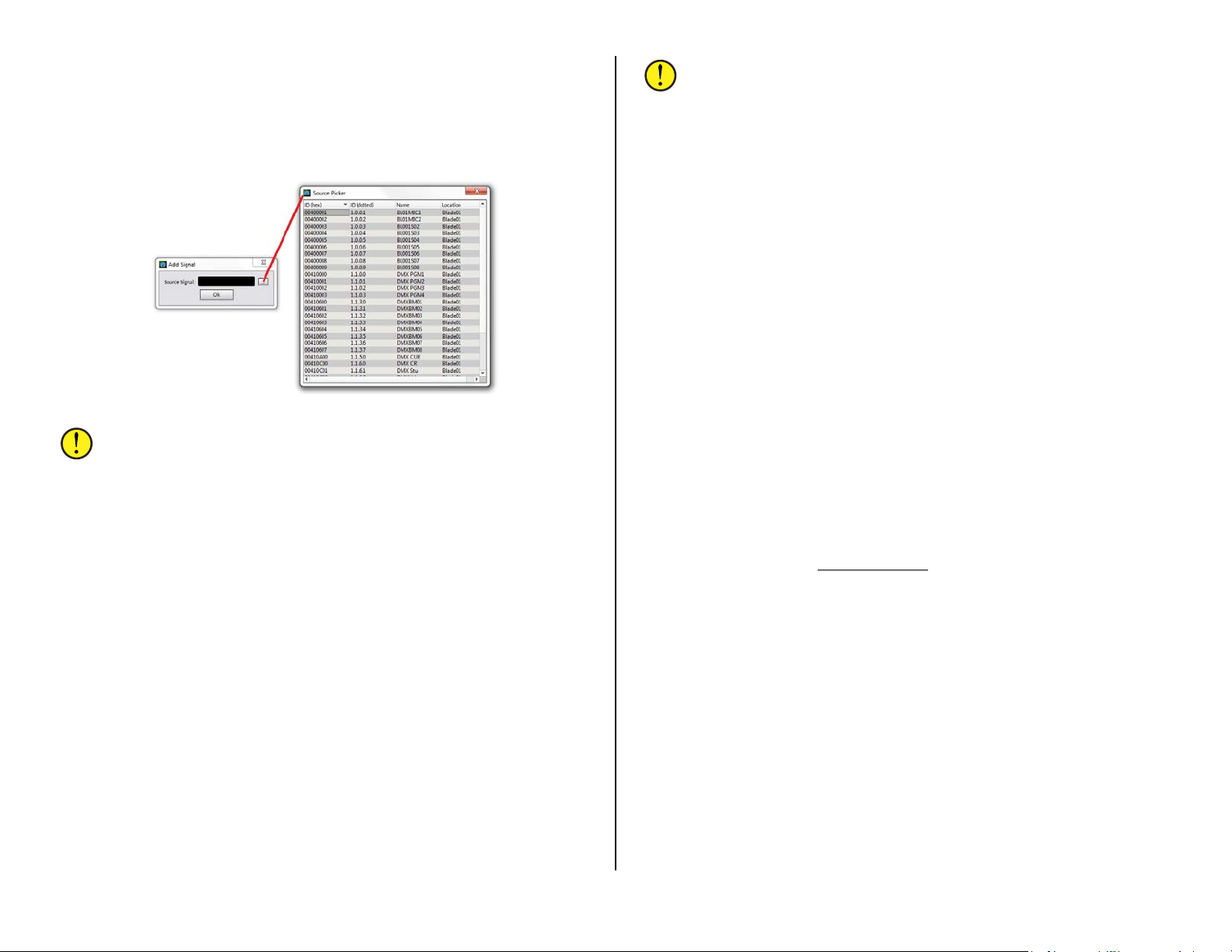
Double-click a sig nal row to select a source, which also closes the Source
Picker. Clicking OK adds that source to the Signals list and clos e s the Add
Signals box.
Repeat this process (click Add…, click the Picker button, double-click on
another source r ow then click OK) for each source you need to configu r e.
Fortunately, this repetitive proc e s s only needs to be done once.
Figure 3-9 Adding a Source to the Signals List
Note: Clicking Apply immediately updates all sou rce settings—
even for sources that are currently turned on, so use caution when
making sources changes when the console is already on-air.
If any Default Options are checked, thos e options are automatically
checked on each newly added signal. Each newly added signal is also
automatically s ele cted (highlighted) so addition a l c onfiguration settings
can be edited as required. To see the effect this has on the sou rc e
channel’s functions, click Apply to send the updated settings to the
Surface.
Options
These nine settings are independently checked for each source to control
what features become active when that source is active on a fader
channel.
PFL/Cue Dropout – This controls what happens when that source’s channel
is turned on. When checked, cue (alternately called PFL or Pre-Fader
Listen) is automatically turn e d off, if active, w hen the channel is turned
on.
When unchecked, and cue is active, cue remains active when the
source’s channel is turned on. This control is ty p ic ally unchecked if Fader
Cue is checked.
Timer Reset – When checked, a Timer Reset command is sent to the tim er
each time that source’s channel is turned on. If unchecked no timer reset
is sent to the timer.
Note: For the Timer Reset function to actually reset the timer, the
Timer Auto button must be lit on the Surface. When the Timer
Auto button is unlit, the timer reset command, even if it is
checked, will not reach the timer .
Machine Start Pulsed – Sets th e type of logic comma nd sent to the
source’s remote logic. When checked a Start Pulse is output. When
unchecked a sustained logic closure (tally) occurs for as long as the source
channel is on.
EFS (Electronic Fader Start) – Controls whether moving the source’s
channel fader affects channel on and off. When checked, moving the fader
to full off turns the channel off. Moving the fader away f rom full off turns
the channel on.
When unchecked fader movement does not affect ch annel on/off status.
This command is typically assigned th e same for all sourc e s , although
some users like to just enable this feature on microphones.
Fader Cue – This setting is simila r to EFS in that fader movement affects
the channel status. When checked, moving the fad er to f ull off turns cue
on and moving th e fader away from full off turns cue off. This action
emulates a feature found on analog consoles that used rotary channel
volume controls to put the cha nnel into cue when the pot was full off.
When unchecked, fader movement has no effect on cue—unless EFS and
PFL/Cue Dropout are both checked, in which case cue is turned off when
the fader is moved from full off.
Remote Ready – When unchecked (the standard setting), the off button
lights up when the channel is off. When checked, the off button lighting is
controlled by that source’s Ready command logic. The ready logic
command is assigned in PR&E Navigator
PGM 4 / Off Line Options
PGM 4 differs from the PGM 1 – PGM 3 buses in that sources can be set
to feed PGM 4 pre-on switch and/or pre-fader by checking the PGM4 Pre
On and PGM4 Pre Fader selections, and leaving the PGM4 Off Line selection
unchecked.
When PGM4 Off Line is checked on Telco sources (hybrids, ISDNs,
codecs, two-ways devices, and so on) the PGM 4 assignment buttons serve
a dual purpose in that they not only s et which sources feed the PGM 4 bus,
they also control what sourc es feed the hidden Off Line or OL bus. T he OL
bus is used solely with callers and r em ote s to create a return signal, which
is minus their ow n audio, so the board operator can carr y on a hands-free
conversation while they’re not on-air. When the caller/remote channel is
turned on, their bus-minus signal switches to the bus assigned in the BusMinus / Base Mix section (most often PGM 1, but could be any P G M bu s
including PGM 4) so the caller/remote hears ev er ything else going to air.
(see Assigning Logic on page 50).
26
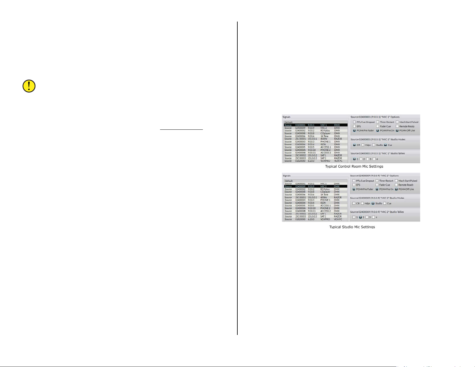
Since there are no Off Line assign b uttons on the console, s ources are
assigned to the OL bus using the PGM 4 buttons. Thus, when PGM4 Off
Line is checked—on any si gna l, the PGM 4 buttons also function as OL
bus assign buttons. Typically, when the OL bus is active the PGM 4 bus is
not used. When PGM4 Off Line is unchecked for all sour c es, the PGM 4
buttons assign the channel sourc e s to the PGM 4 bus like norma l and the
OL bus is not used. In this condition, the caller/remote bus-minus signal is
always derived from the bus assigned in the Bus-minus/ Base Mix section.
Note: The PGM4 Pre Fader and PGM4 Pre On settings affect both
PGM 4 and the OL audio. This means the PGM 4 output, which is
still active even if PGM4 Off Line is checked, could have some
sources active a ll of the time (if PGM4 Pre On is checked) and
those could be at a fixed level (if PGM4 Pre Fader is checked),
which could lead to unexpected operation. Thus, we recommend
not using the PGM 4 bus when Off Line is active (e.g., the PGM4
Off Line option is checked for any source). PR&E Navigator
then be used to connect a different source to the Program output
labeled PGM OUT 4 on the Mix Engine.
PGM4 Pre Fader –When checked that source feeds the OL or PGM 4 bus
without fader lev el control (e.g., the same level as the cue bus). When
unchecked, the channel fader still controls th e lev el feeding the OL and
PGM 4 buses.
PGM4 Pre On – When checked that source always feeds the OL and PGM 4
buses unless PGM 4 Pre Fader is unchecked, in which case the fader still
controls the level. When this option is unchecked, the source only feeds
the OL and PGM 4 buses when the channel is turned on. Typically this
setting is checked for all sources so that no channels have to be on in
order to feed the OL bus.
PGM4 Off Line – This setting affects the bus minus signal sent to that caller
or remote device and affects what th e PGM 4 assign buttons do. When
checked on any source, the PGM 4 buttons also assign their channels to
the OL bus; when unchecked on all sources, the PGM 4 buttons just assign
channels to the PGM 4 bus and the OL bus is not active. For a caller or
remote this mean s they will always h e ar the bus assigned in their Bus
Minus / Base Mix s election (Default setting is PGM 1 for all sources).
Studio Mutes
Any source can be set to mute one or more dedicated outputs when
their channel is turned on. Typically, only microphone s a re set to mute
outputs.
For mics located in the Con tr ol Room, both the CR and Cue outputs are
typically checked (muted). For mics located in a Studio, typically only the
Studio output is checked (muted), unless cue is fed to the studio, then
Studio and Cue would be checked.
can
Usually the HDP N output is never checked. Figure 3-10 shows the typical
settings for a CR mic and a Studio mic.
Studio Tallies
Each mic is typic a lly set to trigger one tally (1 – 4) by chec king one of
the Tallies. Tally 1 is typically us ed for the Control Room a nd Tally 2 is
typically used for an associated talk s tudio. Tallies 3 and 4 can be used to
trigger hot mic wa r ning lights at two othe r loc ations (produce r position,
call screener, newsroom, or other location). Ass ig ning a Tally activates two
Surface displays when the mic channel is on: a red On Air indicator lights
up in the Meter Bridge; and a mic icon, sh own in the channel displa y to
the left of the Mode name, wh ich turns red. These mic status indicators
will not be shown if a mic is not assigned to a Studio Tally.
Figure 3-10 CR & Studio Mic Settings
Bus-Minus / Direc t Out
The DMX includes an internal mono signal associated with each fader
channel as indicated by the 1 – 8 (for a DMX-8 Surface) or 1 – 16 (for a
DMX-16 Surface) check boxes. These signals have the default names:
DMXBM01 – DMXBM16, since they are Bus-Minus audio signals which are
used with callers and remotes. However, these mono signals can
alternately be u s e d to c reate a Direct Out signal of any source to feed
devices like an outboard FX unit, an air skimmer, or a system mon itor.
The settings in this section set which type of signal is generated when
the source is assigned to a channel. If no boxes are checked a bus-minus
signal is created on any channel that source is taken on. When one or
more boxes are checked, and that source is taken on one of the checked
channels, a channel Direct Out signal is created for that source.
27

Note: Direct Out audio is affected by the settings in the Direct Out
Pre Fader and Direct Out Pre On sections.
For Telco devices no channel boxes s hould be checked, so that a busminus signal is created when that Telco device is dialed up on any fader.
This means an IFB (Interruptible Fold Back) a udio signal is created that
can be returned to the Telco device so they can hear the board operator or
the program audio. This also means that any fader channel can have a
codec or a phone hybrid on it, each with its own unique IFB signal.
Bus Minus / Base M ix
This setting is only used when no channels are checked in the Bus-Minus
/ Direct Out section, which means that a bus-minus signal is being created
for this source. This selection sets which bus: PGM 1, PGM 2, PGM 3, or
PGM 4 is used to create a bus-m i nus IFB that’s sent back to the caller or
remote while their channel is on (the OL bus is fed to the caller or remote
while their channel is off). The normal selection is PGM 1.
Note: If PGM4 Off Line is not checked for any source, this BusMinus / Base Mix is always returned to the caller or remote. The
channel’s TB button would then be used to talk back to that caller
or remote.
Direct Out Pre Fader
When checked for the same channel numbers as set in the Bus-Minus /
Direct Out section , the Direct Out audio is sent at a fixed level (sam e level
as the cue bus). When unchecked, the level feeding the Direct Out is
controlled by the chann el fader .
When cue is set to au to-switch into the boar d operator headphones
(Headphone Cue Defeat unchecked), the Split Cue button in the monitor
section on the Surface s ets how cue is fed into the headphones. W hen the
Split Cue button is unlit, cue is fed in stereo, cutting off the monitor aud io.
When the Split Cue button is lit, cue is fed to the left ear while the CR
monitor source is f ed to the right ear.
Level Locked - When checked, a nd the Apply button is then clicked, the
current level of that level encoder ( CR, STUDIO, or HDPN) is fixed at that
output. Turn ing that encoder will no longer affect the volume of that
output. Uncheck Level Locked then click Apply to return level c ontrol to
that encoder. Checking Level Locked: would be used when a studio-
mounted volume control (like that found in a TS22 talent station) is
available, checking the Studio Level Locked would allow the TS-22 to
control the monitor volume; the Headphone Level Locked would be
checked when mics have talen t s ta ti ons or when an external headphone
amp and cabinet-mounted level control/headphon e jack panels are us ed.
Direct Out Pre On
When checked for the same channel numbers as set in the Bus-Minus /
Direct Out section , the direct out audio is not affected by the channel
on/off status. The audio is always feeding the Direct Out unless Direct Out
Pre Fader is also unchecked, then the channel fader affects the level going
to the Direct Out. When unchecked, the Direct Out audio follows the
channel on/off status.
Monitor Config Page Tab
This page tab’s settings affect the CR, STU, and HDPN monitor outputs
on the Mix Engine. The Headphone setting also affects the board
operator’s headphone jac k on the right side of the DMX Surface.
Cue Defeat - When checked the cue system does not affect that monitor
output. When unchecked, any channel with cue turned on gets switched
into that monitor ou tput replacing the mon itor audio. The normal setting is
Cue Defeat checked for the Control Room an d Studio and unchecked for
the Headphone output (as shown in Figure 3-11, left illustration).
Figure 3-11 Monitor Config & Buttons Page Tab Entries
Buttons Page Tab
Figure 3-11, right illustration, shows the five available functions in the
drop-down list that can be assigned to the Soft button in the monitor
section of the DMX Surface. Once the function is selected, PR&E Navigator
is used to configure the logic using the settings: Switch 1 and Switch LED
1. Here’s what each function does and what each could be used for:
• None – The default setting. The switch and LED have no assigned
functions and the button does not light when pressed.
• Tally – Sets the Soft button LED to function solely as an indicator
with no switch functionality. Add a new logic-only destina tion in
PR&E Navigator
LED 1 (see Assigning Soft Bu tton Functionality on page 41). The
Spare01 source is then connected to the new LIO destination in
the PR&E Navigator
28
with the Direction: input and the Function: Switch
crosspoint tab. When that logic input is
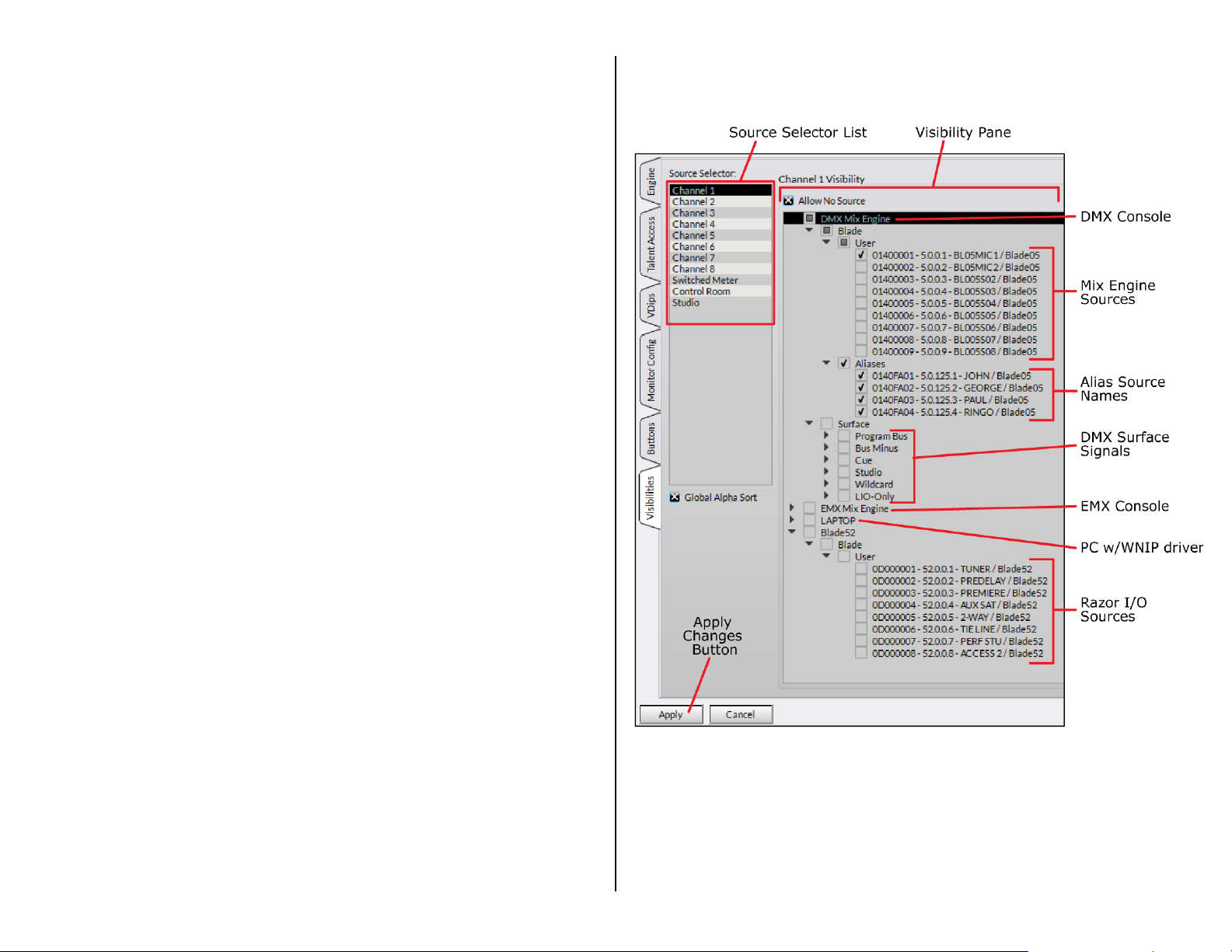
triggered, the Soft button LED lights up. This setting w ould be
used to create a hotline phone ring indicator.
• Toggle – Sets the switch to function as a sustained mechanical
toggle switch. A logic-only des tination is created with the
Direction: output and Function: Switch 1. The Surface itself
controls the button LED, indicating whether the output logic is on
(button is lit) or off (bu tton is unlit). This setting migh t be used to
control studio access (studio door loc ked = lit, unloc ked = unlit).
• Momentary/Surface LED - Sets the switch to be momentary. A
logic-only destina tion is created with the Direction: output and
Function: Switch 1. The Surface controls the button LED, lighting it
to indicate the button is being pressed. This setting might be used
to create a talk bu tton to talk to a call s c reen or producer p os ition.
• Momentary/LIO LED – Sets the switc h to trigger a logic output
while pressed and sets the LED to be controlled by a logic input. It
combines the logic-only settings for Tally and Toggle. Th is s e tting
could create a profanity delay Dump button, with the LED being
the Safe or Dump Ready indicator.
Visibilities Page Tab
Each DMX source selector: fader channel; CR monitor; Studio monitor;
and Switched Meter, has its own Visibilities List to set whic h alternate
sources are displayed whil e using that type source selector.
The default Visib ility setting for all selectors is to display all sourc e s . This
is desirable for in stalling the console since it allow s any source to be
“dialed up” anywhere. But, for daily operation of the console, it’s essential
that the Visibilit ie s lists--especially on the fader channels, are edited to
remove signals that should not be s hown, like the PGM bus es a nd other
internal console signals as well non-air sources like pre-delays and tuners.
Figure 3-12 shows the Visibilities page tab with the Chan nel 1 Source
Selector highlighted. This channel is typically ded ic ated to the board
operator or host mic. In the exa m ple, there are five sources ch ec ked: the
left channel of the Analog I n 1 jack (BL05MIC1), plus four Alias names,
and Allow No Source. When th e c hannel 1 encoder is rotated, NoSource,
BL05MIC1, GEORGE, JOHN, PAUL, and RINGO will appear in the
channel 1 display. If NoSource is taken, it s ile nces that channel. Taking
any other source displays that name which, in this case, includes four
“talent names” all associated with MIC 1.
If Allow No Source is un checked that name won’t appear in that list of
alternate sources. This is typically done on the Switc hed Meter, Control
Room and Studio selectors since they should not be silen c e d at any time.
The default Visib ility setting, f or all selectors, is to display all sources.
But, for daily ope r a tion of the console, it’s essential t hat the list of visible
sources be narrowed, if only to prevent a Program bus from being tak en
on a channel and then assigned to the same bus. Doing this will cause
“digital feedback” a s the fader is potted up which ca n over load the bus,
causing it to mute.
Figure 3-12 Visibilities Page Tab Settings
Visibility List s
On fader channels with a dedicated sour ce, like the Host mic or phone
channel, only one source, or maybe several talent name Aliases are
checked along with NoSource.
On media server playback ch a nn els , there is often a B Serve or backup
server, so typically the main a nd B Serves on the media server ch a nnels
29
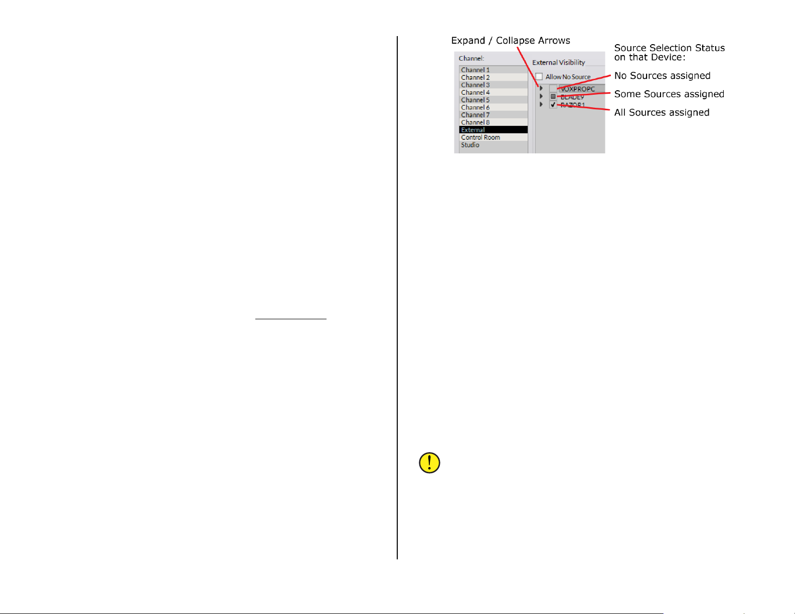
are checked. On fader channels with a “regular source,” which might only
be used periodically, like a CD player, Instant Replay, or a traffic service,
checking a han d ful of alternate sour ces adds flexibility to those fader
channels.
Most users set up the last two or three f a d er s nearest the monitor
section as “re m ote line selectors” which typically have every sour c e which
might go live to air, or need to be recorded, checked. Of course, these lists
would still exclu de the Surface signals and sources like off-air tuners and
processed pre-delay m onitor signals.
Telco Devic e Visibilities
In previous PR&E consoles, Telco dev ic es c ould only be included, or
made visible, on fader ch an nels specifically-designated as “Telco
channels.” Telco faders had a unique mix-minus signal associated with that
channel which created the return signal for the Telco device.
On the DMX, every fader channel has its own bus-minus signal to create
a mix-minus return signal for a Telco device. This means there are no
channel restrictions so a Telco device can be set as visible on any fader
channel.
When a Telco device can be taken on various channels, when it is taken
that channel’s bus-minus signal must be connected to that Telco device.
This could be done m a nually, but it can a lso be done automatically by
creating an Associated Connection, for each Telco device and each channel
that it’s set as v isible on . These are assigned in PR&E Navigator
34 for an overview of using Associated Connections with Telco devices.
. See page
Setting the Visibility List
Click on a name in the Source Selector: list. That Channel number,
Switched Meter, Contr ol Room, or Studio is then highlighted and its
current settings are shown in the Visibility Pane. The Visibility Pane title
also shows the highlighted selector’s name.
When first selected, all system devices are shown collapsed (Figure 3-
13) with boxes indicating which sources are selected on each device. An
empty box means no signals are selecte d; a filled box indic a tes at least
one signal is selected; and a checked box indicates all signals are selected
(the default sett ing on a new console).
Click on a right-facing a r row to expa nd that device (the arrow then
points down). Sub-categories (Blade, Us er , Surface, etc.) are expanded in
like manner until you reach the source names (as shown in Figure 3-12 on
page 29). The sub-categories and devices are selectively collapsed by
clicking their down-facing arrows, which then poin t right again.
The current expanded/coll a ps ed view is maintained when switc hing
between channel and monitor selectors—until the app is closed. Reopening
the app will again show all devices as c ollapsed.
Figure 3-13 Visibilities Controls
Visibility Pane
Figure 3-12 (page 29) shows the expanded sources for a DMX console
(Mix Engine and Surface) and a Razor I/O Interface. Two other devices, an
EMX console and a PC are shown collapsed. The Program bu s es a nd other
internal bus signals appear under the Surface sub-category below the Mix
Engine. These sig nals are all normally unselected on channel selectors
while many will be set a s visible on the monitor and meter selectors.
When a device is fully expanded in div idual signals have their own
checkbox. When checked, that signal is visible. When unchecked, that
signal will not appear as an alternate source on that selector.
The Allow No Source selection is checked by default so that NoSource
can be taken to silence a channel. It also serves as a handy signal list
divider so you can tell when you’ve wrapped around the sourc e lis t and are
back at the top of the lis t again. Un-checking Allow No Sour c e is typically
done on the monitor and meter select or s so that NoSource is not an
option on those selectors.
The Source Selector: channel, monitor, an d meter s electors have a
right-click context menu that a llows the visibili ty setting from one selector
to be copied and pasted into another selector. After setting a s e lec tor’s
visibility list, right-click on its highlighted selector name and selec t Copy
then right-click on another selector and select Paste to update tha t
selector’s settings.
Note: There is also a Paste All selection in the context menu.
Selecting this pa s te s the copied list of s ources to every channel,
monitor, and meter s elector.
Once the signal visibility is set, w hether for one channel or for all
channels, click Apply to transmit the ch a nges to the Surfac e. The source
selectors will immediately update an d use the new visibility lists.
30
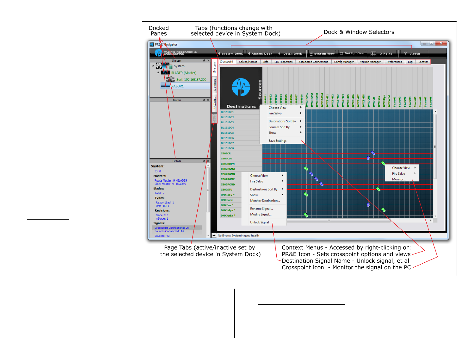
Global Alpha Sort
Figure 3-14 PR&E Navigator Controls Overview
This option is typically checked s o that
the visible source names are listed in
alphanumeric order, regardless of which
device the source is physically on. As
each source name is highligh ted, th e
name of the device it’ s on is shown
above the white line . This allows sourc e s
with the same na m e , like PGM 1, but
which are on different devic es to be
identified withou t having to assign every
signal a unique name. Identical source
names, even if on the same device, will
still appear as separate entries in the
list, but we recommend trying to us e
unique names—if only to make it easier
for board operator’ s to select the cor r e c t
source.
When unchecked, sourc es are s orted
and listed alphanumerically by their
device. The devices are list ed in Blade ID
number order. Thus Blade 1’s sources
will be listed in alphanumeric-order first,
then Blade 2’s source na mes w ould be
listed, then Blade 3’s names, and so on.
PR&E NAVIGATOR APP
PR&E Navigator (Figure 3-14) is used
to initially configure the input and output
signals on the Mix Engine and Razor I/O
Interfaces and to connect sour c e s to
destinations. These actions can be don e
without havin g a license, but advanced
features like updating Blade softw are are
locked out until a site license (gratis) is
obtained from Wheatstone/PR&E
technical support.
After initially configuring the audio and logic signals , PR&E Navigator is
mainly used to connect sources to destinations through using the
Crosspoint grid or by using Salvos. Its main functions include:
• Setting the mode for physica l in puts and outputs between stereo and
dual mono (discrete 5.1 surround signals are also supported)
• Editing the names of the consoles sour c e s a nd destinations
• Viewing and updating the Mix Engine and Razor software
31
• Manually configuring system devices (in lieu of using the automatic
PR&E System Configuration Tool
• Assigning a specific Mix Engine to be the system master or clock
master in a multiple-console system
• Assigning system-wide settings like the system’s sample rate and the
date and time shown on the Surface monitor displays
)

• Assigning the LIO and SLIO (Logic Ins or Outs) that are available on
Figure 3-15 Signal
each device
• Creating Assoc ia ted Connections, based on system activity, that
automatically make other signa l c onnections
• Showing what devices are connected in the system
• Logging system a c tivity
To start PR&E Navigator double-click its desktop icon or,
from the Start M enu, select All Programs > Whe a ts tone PR&E
> PR&E Navigator.
PR&E Navigator opens showing the System Crosspoint Tab
(Figure 3-14 on page 31). A Login popup box also ap pea r s .
When first usin g the app, just click OK to close the popup since no
password is set by default. We do recommend setting a password (click
Set Password… on the popup window)—especially when PR&E Navigator
run on a studio PC, since improper use of the app could cause unexpec ted
audio connection changes a nd other undesired DMX operation .
is
System Tabs
The System > Crosspoint Tab is shown when the app starts. Clicking
on a Blade, Surf ace, or other device icon in the System Doc k changes
what’s displaye d, as will clicking on a differen t System tab or on a
different Page Tab. To re-display the Crosspoint Grid, c lick the System
icon in the Syste m D oc k, or the System page tab, then click the
Crosspoint ta b. A separate Crossp oint Grid floatin g window can also be
opened by clicking the X Point window selector .
The Crosspoint grid shows the system sources (horizontal axis) and
system destinations (vertical a xis) with icons indicating connected signals
in an XY grid. The sig nal name colors match the device colors shown in the
System Dock. These colors can be changed using the Blade Preferences
section of the System > Preferences tab.
Connected audio s ignals are shown by small round dots. The dot colors
indicate signal level (purple = n o or very low signal, green = normal level
signal, red = high level signal). A single dot indicates a mono connection.
Two dots at a 45° angle indicate a ster eo source connecte d to a stereo
destination. I f there are two dots stac ked vertically the source is mon o b ut
the destination is s te r eo. Likewise, tw o horizontal dot s indicate a stereo
source connected to a mono destination.
A green square indicates a logic-only crosspoin t.
A red circle aroun d a crosspoint indicates a fault in operation (the
destination could not subscribe to the source). I f the crosspoint is actua lly
connected (one or two round dots ar e shown within the circle) then th e
error just needs to be cleared by closing and restarting PR&E Navigator
.
Connecting Signals
As you mouse over the grid, pur ple X-Y crosshairs point to a source and
a destination so you can easily identify which signals will be connected if
you click on that crosspoin t in the grid. Click ing on a crosspoint adds an
icon to indicate that connection is n ow active. To disconnect a signal, click
on an active cros spoint to silence th e d es tination on an audio connection
or turn off the logic on a logic crosspoint.
As a safeguard, to prevent accidental connections or d is c onnections, you
can require the CTRL key be pressed while clicking on the grid to make or
break a connec tion. This option is se t in the General section of the System
> Preferences tab.
Destinations w ith a horizontal red line across the grid indicate they’r e
locked from change since they’re actively in-use. These signals may be
system-assigned (like PGM 1 connected to the PG M 1 output) or they are
Surface channels which are currently turned on. Regardless , any locked
signal can be unlocked by right -clicking on the Des tination name and
selecting Unlock Signal from the context menu.
Note: Use caution when unlocking channel destinations DMXIn01
– DMXIn16, since the red line indicates that channel is currently
turned on, and dedicated outputs feeding air (like the “PGMA”
output) or going to an internet strea m er since changing their
sources would affect your air or stream feeds.
Remote Monitoring of Audio Signals
Right-clicking on an active c rosspoint connection,
on a source nam e , or on a destination na me brings
up a context menu (as shown in Figure 3-14 on
page 31). Selecting Monitor…, Monitor Sour c e…, or
Monitor Destination… opens up a Monitor window
(Figure 3-15) showing the source levels and, if that
signal is connec ted to a Destination , the Destination
levels.
The bottom part of the window has controls to
listen to the audio. A drop down list sets which PC
audio destination to use to listen to th e signal
(typically the PC’s built-in speakers). Click Listen
to Source… to hear the audio in your PC speakers
or headphones. Use the Volume control to adj ust
the listening lev el.
Note: This monitoring featu r e is even more valu able when you
remote into the system from home or the road since the a udio
plays back on that remote PC allowing one to confir m the correct
audio is present. F or r e m ote access into your admin PC we
recommend using TeamViewer 12.
Monitor Pop-Up Window
32

Salvos/Macros Tab
Figure 3-17 System Info Tab, Detail
Figure 3-17 Info Tab
Clicking the System > Salvos/Macros tab shows a display that looks
like an unpopula te d Crosspoint grid. The difference is that this grid is not
“live.” In the Sa lvo grid (Figure 3-16) the signal connections needed for a
future show, daypart, or special event are selected and saved as a Salvo,
which means that all of the conn e c tions get taken immediately when that
Salvo is later “fir e d.”
Dozens of audio and logic crosspoint connections can be set and saved
in dozens of Salvos. Each Salvo begins life as a number (S a lvo 1, Salvo 2,
and so on) which doesn’t mean much so you’ll w an t to rename any Salv os
you create (select the Salvo in the drop down list then click Rename). Use
a name that easily indentifies what the Salvo was created to do.
Even though you c an enter a name with a n a lmost unlimited num be r of
characters, only about 25 characters are actually shown in the Salvo drop
down list. However, when you assign a salvo using the LIO tab, only the
first eight characters are shown, so it’s best to limit your names to eight
characters, like: DanceRMT; SuperPre; or GrdnShow or at least make sure
the first eight characters can be used to identify the s alvo.
previous Salvo are remove d so you have a clean slate. As soon as you
make the first connection “(empty)” is rem oved from the nam e indicating
that Salvo is in-use. There is no Save Salvo button sin c e the active Salvo
is updated with every edit.
When you select a S alvo from the drop down lis t its connections are
shown in the Salvo Edit Screen in rea d -only mode. The Details Dock also
lists that Salvo’s c onnections by their destination and source names. To
make further changes, click the Editable button to allow connections to b e
added or removed.
To take the Salvo, se lect it from the drop dow n list then click Fire. The
crosspoints assigned in the Salvo are all immediately connected—except
for any connection on a locked destin a tion, like channels that are turned
on, their conne c tions are not made. To make those connec tions, turn off
the channel(s) and fire the Salvo again. You can also assign the Soft
button in the monitor s e c tion of the DMX Surface, or a button on a
programmable button panel, to fire a salvo.
Info Tab
This tab’s main use is to set
the date and time (highlighted
in Figure 3-17) which appear in
the Surface’s two monitor
displays. Check Use this PC’s
time then click Apply to update
the clock and time on the
monitor displays. If the admin
PC is always connected to the
Internet, click NTP to assign a
remote time server to keep the
system time sync hronized.
The other setting on e m a y
want to change is the Clock
master sample rate which can
be set for 44.1 or 48 kHz. The
other section’s s e ttings should
be left at their default settings.
Figure 3-16 Salvo/Macro Tab
Click New to create a new Salvo with the name Salvo X (em pty), with X
being the next unused Salvo number. Any existing connections from the
LIO Properties Tab
This tab (Figure 3-18 on page
34) is used to set the
unconnected state condition for
the User-defined logic f unctions
(User 1 – User 500). Each Userdefined logic fu nction one can be
set its state to High, Low, or leave
in its Last State when
33

unconnected. The default setting is Low. This tab also shows the settings
Figure 3-18 LIO Properties Tab
for the pre-assigned logic (those settings cannot be edited).
Associated Connections Tab
This tab is used to create, view, and edit Associated Connections, w hich
can be used to automate console or system operations. An Associated
Connection con s is ts of two parts: a Triggered Connection a nd one or more
Associated Connections . Wh en the triggered connection is ma de, the
system responds by automatically making the specified Associated
Connections.
Associated Conn ections are often created for Telco d evices in order to
automatically c onnect the correct b us-minus sign a l to the Telco device.
This is shown in Figure 3-19, but one can automate many system
operations in res ponse to a preset trigger con nection (either a n audio or a
logic connection c a n be set as the trigger) by defining one or mor e
Associated Connections.
A Triggering Connection is assign ed b y clicking Add… in the Triggered
Connections: section of the tab to open the Add Triggered Conn ec tion
dialog box where a source and des tin a tion are selected. In the ex a m ple,
PHONE 1 taken on channel 12 is the triggered con nection. Clicking OK
adds that entry to th e T r iggered Connections list.
With the triggered c onnection highlighted, click the Add… button in th e
Associated Connec t ions: section to open the Add Associated Connection
dialog box to select the source and de s tination to be conn ected in
response to the trigger connection being made. In most cases you’ll want
to checkmark the Lock Override option. When checked, and the trigger
connection is det ected, the selected source will be co nnected to the
destination even if another sign al is connected an d the d estination is
locked. When Lock Override is not checked, th e Associated Connection
would not be made on loc ked destinations.
Multiple Associa ted Connections c an be assigned to occur with a single
trigger connection. Once all of th e Associated Conn ections are assigne d,
click the all-important Apply button to tell the Blade w ith the Triggered
Destination to mon itor the system waiting for the triggered connection to
occur. When it’s made (in the ex a m ple P H O N E 1 is taken on channel 12)
all of the Associated Connections a ssigned to that tr iggered connection are
immediately connected.
Figure 3-19 Associated Connections Tab
More details on setting up and using Associated Connections can be
found on page 42.
Config Manager Tab
This tab (Figure 3-20 on page 35) is used to backup or restore parts of
or the entire system ’ s configurati on.
It’s important to periodically sav e a sy s te m backup (especially after you
finish completely setting up a system) so that your sy s tem settings are
saved so they can be restored to any system device if there’s a failure and
that device needs to be r eplaced, or if a factory reset needs to be done for
some reason.
The Current Crosspoint: section of the tab also allows you to save all
of the current Crosspoint connections to a file whic h can later be recalle d
to restore those cros s point settings. Clicking Save saves the current
crosspoint connections to a file in: Documents > Whea ts tone > Navigator
> Connections. Clicking Restore… opens up a dialog box to select between
various saved c rosspoint connection files.
34

If you manually r e name the saved crosspoint files by an activity or a
daypart (their default nam es use the saved date and time) then one can
use the Restore function as an alter native to using a salv o to e s tablish
crosspoints. Th e r e is one very important caveat: using Restore Crosspoint
overwrites lock ed s ignals (includin g ones locked because that signal is
currently on-air)—even if the crosspoint source is differen t than what’s
currently connected, whereas using a salvo does not change sources on
locked destinati ons (like on-air channels).
Figure 3-20 Config Manager Tab
then click Restore to restore the c onfiguration settings held in that saved
configuration folder. Once the se ttings are restored, any Blade tha t is
being restored must be reboo ted in ord er to u se the restored settings.
Version Manager Tab
This tab (Figure 3-21) is used to update a Blade’s (PR&E Mix Engine,
Razor, and M4IP-USB) operating system code. The current code release is
included as part of the PR&E Navigator
may also be a new version of operating system code included.
Note: Updating the operating system code requires that your copy
of Navigator be lic ensed. Contact W heatstone/PR&E support to
obtain a license.
In the Blades av a ilable for update: section, checkmark which Blades
to update. Blades ca n be updated one a t a time or all at once. Click Select
All to checkmark all Blades. Click Clear All to uncheck all B la d es .
Once the Blades you want to update ar e c hecked, click Update… to open
a dialog box to selec t the binary code file with the updated c ode . In most
cases there will on ly be one file in the d ir ectory. Select th e file and click
Open to load that file. A warning dialog box pops up asking the age old
question: Are you sure? Click Yes to load the new code or No to cancel the
update.
Even though PCs running the WNIP driver are listed as Blades in PR&E
Navigator, they are not updated using this process. They are listed in the
Blades not availa ble for an update: section of the tab solely so you can
view their WNIP a udio driver software version, wh ich also need to be
updated when your Blades ar e updated.
app, so if that app is upda ted there
The Configuration Folder: section sets the folder path f or saving your
configuration files. The default is: Documents > Wheatstone > Navigator >
cfg. Clicking the … button opens up a save dialog box where the path can
be changed. Clicking the Default button restores the save f olde r to the
default path.
The Backup System C onfiguration: section allows all sy s te m s e ttings
to be backed up by clicking Backup…. A pop-up warning box appear s
listing the filename, which includes the date and time. Clicking Yes saves a
separate Blade Con fig file for each blade within a ma in folder. The saved
configuration folder is then listed in the Restore System Configura t ion:
section of the tab. Each of the f olders c a n be expanded to view the saved
file names.
The Restore Syste m C onfiguration: section is used to restore a saved
configuration. The check boxes, in the Restore: section, allow you to
select which system devices a nd settings will be restored wh en the Restore
button is clicked. Click on the nam e of a saved configuration folder and
Figure 3-21 Version Manager Tab
35

Note: There will be no audio interruptions while th e c od e is
uploaded, but you must reboot the Blade to run the updated cod e.
Rebooting will cause momentary audio interruptions as the Blades
complete rebooting and all existing connections are remade.
Preferences Tab
This tab (Figure 3-22) sets PR&E Navigator’s appearance and some of its
functionality. The General section Default View: sets whether the default
crosspoint view (No V iew) or a custom view is shown when PR&E
Navigator opens. Default Grid Labels: sets how the source and
destination names are listed as: name only; names and location; name
and signal format; or signal ID and name. The De fault Sort Order:
section sets the or de r in which the S ource and Destination names are
displayed and how the Blades they are on are listed in the grid.
The five check b oxes at the bottom of the General section set: how
Source and Destination signal ID numbers are show n (Use dotted Signal
IDs rather than hexadecimal); the overall look of the Naviga tor app
(Use Style Sheet); whether 12-hour or 24-hour is used in Navigator (Use
24 Hour Time); how a crosspoint connection is made or broken (Use
CTRL+click to mak e/break a crosspoint connection); and whether to
show the Logger section (Enable Advanced Controls).
The Blade Preferences section allows each Bla d e’s color to be edited
by double-clicking on a Blade Name. A Select Color window open s so a
new color can be a s s ig ned to that Blade. The color setting not only affects
the color of the Blade names in the dock, it also af fects signal name color s
in the crosspoint and salvo tabs, and the color of log entries from that
Blade. Since System Announcer log messages are black we don’t
recommend assign ing that color to a B la d e.
The Crosspoint Preferences section a llows one to customize how the
Crosspoint grid looks. You can change the color of the normal pointer
crosshairs (Grid Hilite); the color of the crosshairs w hen over a crosspoin t
with Associated C onnections (Assoc Hilite); the color of the audio
connection dots fr om their default purple, green, and red; the color of the
logic connections from the default green; and change the grid background
and grid logo.
The Default Crosspoint b utton allows you to return the settings to their
defaults after “ customizing” didn’t work out the way you thought it would.
The Salvo cross p oint display can like wise be customiz ed a s well knowing
the Default Salvo bu tton can be pressed to return it back to its “ s toc k”
settings.
The Logger section is only shown when Enable Advanced Controls is
checked in the General s ection. These settings affect the Sy stem Log
operations and the Log tab. We recommend using the default settings, but
if a change is made, clicking Set applies the updated settings. Click Open
to open up the E2Log s folder which is wh e r e the various types of log files
(text files) can be viewed.
Figure 3-22 Preferences Tab
The Network section shows which NIC Navigator expects is connected
to the PRE-IP network . If no devices appear in the System D oc k, look at
the NIC address shown here. If it is not c or rect, click Set… to open a d ia log
box listing all of th e NICs in the admin PC so the correct NIC, which should
be an address in the 192.168.87.0 s ubnet, can be selected.
Log Tab
The Log tab (Figure 3-23 on page 37) shows system messages sent by
the PRE-IP devices from the day and time Navigator
was last started.
36

Its main purpos e is as a troubleshooting tool, although you can get a
good sense of networ k communica tions by observing the log as the system
is in use.
The log saves a log f ile each day but the log is r es e t each time Navigator
is started, so if you want a complete lo g of operations we recommend
keeping Navigator running on a t least one PC connecte d to your PRE-IP
network so you have an on-going log just in case you do run into problems
or unexpected operation.
Figure 3-24 Locator Tab
Blade Tabs
When any Blade: PR&E Mix Engine, Razor I/O Interface , M4IP-USB, or a
PC or audio server with a WNIP driver, is selected in the Sys te m D oc k the
list of tabs change from those shown while System is selected to show the
various Blade tabs (Figure 3-23).
Figure 3-23 Log Tab
Locator Tab
This tab (Figure 3-24) shows all of the Blades and Surfaces connected to
the network. C lic k Refresh to rescan the system and refresh the view. Note
that a similar view is ob tained by clicking on System View but in that view
the Surfaces are shown under a separate tab from the Blades.
Just as with the DMX Surface Setup Locator screen clicking on a device
lists its properti e s in the Set Selected Device Properties section where
the settings can be viewed and manually edited by advan c ed users.
Figure 3-23 Blade Tabs
The Blade tabs allow one to update the s e ttings for tha t Blade’s input
signals (Sources tab); its output signals (Destinations tab); to save
and/or print out a list of input and ou tput connections (Wire Info tab); to
view and test the device’s logic con nections (LIO Info tab); to view and
edit the Blade network settings (Blade Info); and to save or restore th a t
Blade’s settings (Config Mana ger tab). The M4IP-USB Blade has two
additional tabs: Silence Sense and Utility Mixer.
37

Sources & Destinations Tabs
These two tabs ha ve identical sections used to na m e each Source or
Destination sign al; edit their settings; associa te logic commands with
audio signals; add or edit logic–only signals; create signal Aliases; and edit
the Blade’s locat ion name. The Sources tab is shown in Figure 3-24.
The lower half of each of these tabs (the Meters: section) shows signal
levels for the physical in puts (on the Sources tab) or outputs (on the
Destinations tab) on that Blade. Just below the meters a r e level controls
and, for stereo signals, a balanc e c ontrol. The level controls allow each
signal level to be adjusted by up to +/-18 dB from nomin a l. Details on
using the level and balance contr ol ca n be found on page 39 in the Lev el &
Balance Contr ols section.
might be edited to MIC 1 and MIC 2 or to HO ST and GUEST (any name
using up to eight characters). Input signals are edited using the Sources
tab (Figure 3-24). To see this tab, click on the Mix Engine ic on (Blade01)
in the System Dock then click the Sources tab.
To edit a name, click on the name in the Source Signals section of the
tab then type in a new name of up to eight characters. You can alternately
click once on the name then click Edit… to open the Signal Edit window
(shown in Figure 3-25) and edit the name within that win d ow.
Changing the Signal Type
If you aren’t planning on using the two built-in mic preamps on a Mix
Engine or on an Analog-only Razor, two other mono s ources, like a pair of
phone hybrids, or a phone hybrid and a codec, cou ld alter nately connect to
Analog In 1. If no mono signals are bein g connected, th e two mono Analog
In 1 signals can be ch a nged into a single stere o input by clicking on
BL01MIC2 to highlight it, then c lic king Delete to remove that signal—after
clicking Yes on the “Are You Sure?” pop-up box.
Select the other mono signal (BL01M IC1) and click Edit… to open the
edit window (Figure 3-25). Change the Signal Type selection from M ono
to Stereo. You ca n then edit the name ba c k to a generic name like
BL001SO1, to indicate Ana log In 1 or, if you know what stereo device w ill
be connected to that input, enter the device name in the Name entry box.
Click Finish to close the Edit Window.
Figure 3-24 Sources Tab
Naming Signal Inputs and Outputs
Every Blade inpu t a nd output signal has a default name which can be
edited using the Blade > Sources or Blade > Destinations tab to
identify the periph er al device or th e s ig nal connected to the various inputs
and outputs. The internal signal names (PGM buses, console channels,
bus-minus signals, etc .) are typically left us ing their defau lt names.
As an example of h ow to edit names, the PR&E M ix Engine Analog In 1
signals have the defau lt n ames of BL01MIC1 and BL01MIC2 s ince those
two inputs are meant to jumper to MIC S OUT. These two sign a l names
Figure 3-25 Editing a Signal
Note: You cannot edit a source or d estination signa l while it’s
connected in the Crosspoint grid. Wh en the Signal Edit window
opens (Figure 3-25) look at the bottom of the win dow to verify it
shows “Signal is not connected.” I f it shows “Signal is c onnected”
you won’t be able to m a ke any changes to th a t signal other than
editing its name.
38
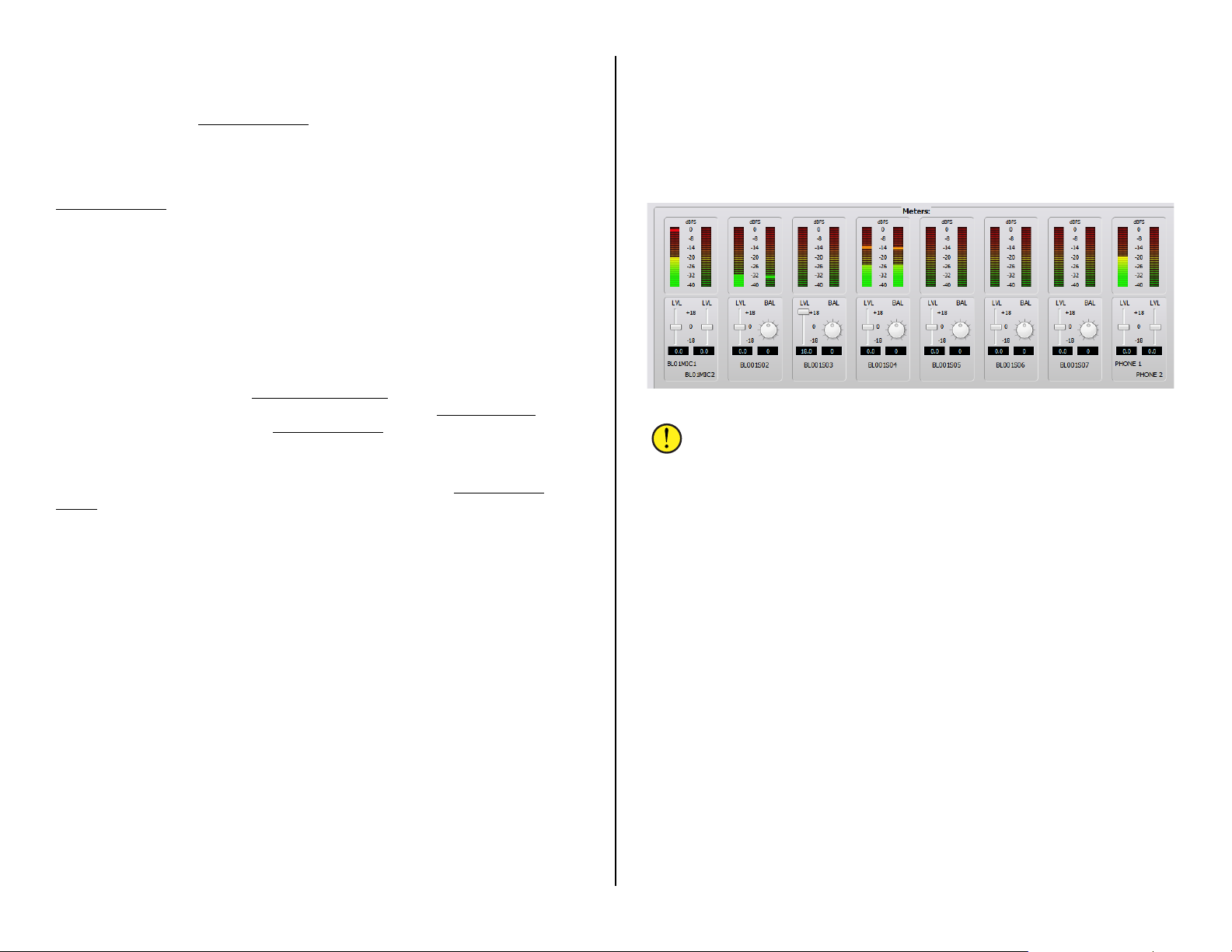
Creating Aliases
A source or destination may need to have a different n a m e displayed,
depending upon where or how the signal is being used, which differs from
the one assigned in PR&E Navigator. To accomplish this, an Alias can be
created for any signal. An Alia s is often used with mics to allow them to be
named as: MIC 1, MIC 2, MIC 3, and so on in Navigator, but each mic can
have multiple Aliases created so that “Talent names” appear in the channel
displays instead of the generic names (MIC 1, MIC 2, and so on) set in
PR&E Navigator
To create an Alias, click on a Source name (you can also set up an Alias
on a Destination or on a logic signal, but most often an Alias is created for
a Source) then click Add Alias…. As an example, to create an Alias for
BL01MIC1, clic k on that name (high lighted in Figure 3 -25 on pa ge 38)
then click Add Alias… to open up the Add Alias window. Type in the
“Talent’s name” in the Name: entry box. Click Finish to close the Add Alias
window. The Alias name is now added as a c ompletel y new “source” in the
source list.
Once you add alias names and complete editing the source and
destination names, use the DMX Surface Setup
Scan (as shown on page 21). This action updates the Surface Setup
with the changes you made in PR&E Navigator
and adding the new Alias names to the Source and Destination lists.
Even though each Alias is associated with a specific source or
destination, each Alias is treated as a new signal by the DMX Surface
Setup app. This means you h av e to add Aliases to the c hannel Visibilit ies
lists and assign the same VDip settings (as shown on page 25) as you
assigned to their actual sources (especially settings like CR, Studio, and
Cue mutes and stu d io ta lly settings for microphone aliases).
.
app to run a new System
app
, updating the signal names
Level & Balance Controls
The Meters: section of the Sources and the Destinations tab (Figure
3-26) shows the levels for the eight stereo/16 mono inputs, or the e ight
stereo/16 mono outputs, on the selected Blade (note that a Mix Engine
only has stereo ou tp uts).
Below each meter are level (LVL) controls for mono inputs or outputs.
On stereo inputs or outputs there is a level and a balance (BAL) control.
These controls ar e p r ior to the meters so c hanging the level or balance is
reflected in the m ete r display when au d io is present on that input or is
assigned to that output. Since the level control affects the audio in real
time, use caution on live consoles when adjusting lev e ls .
Levels are adjusted using any of these methods:
• Click/drag the level control u p (for gain) or down ( for trim)
• Click above/below the level control to add/subtract .5 dB per click
• Click/hold on the BAL control and drag around the control to pan
the signal left/right
• Directly enter the amount of gain /trim or balance by highlighting
the level or balance entry number then type in a new number. For
levels, numbers from -18.0 up to +18.0 are valid. For balance,
numbers from -100 (full left) to +100 (full right) a r e valid. Press
Enter to assign the new gain or balance entry
Figure 3-26 Meters: Section of the Sources and Destination tabs
Note: The top of the average signal bar graph should be around
the -20 mark with the peak LED around the -8 m ark (to allow for
headroom). On Razor I/O Interfaces, these meters only show
average level bar graphs.
The DMX Surface meters hav e be tter r e solution than the on-screen
meters so they should be used for the most accu r a te in put level
adjustment. Connect a test tone, a t +4 dBu, from a connected device.
Adjust the input c ontrol so the top of the ba r graph is at -20 dBFS on the
on-screen meters. Assign that signal to a DMX channel. Set the channel
fader to align with the -12 dB unity gain arrows. Turn the channel on and
assign it to a Program b us (with no other c hannels assigned to th a t b us).
The DMX Surface meter’s bar graph should light up all of the green LEDs
and one yellow LED , which is the -20 dBFS p oint on the DMX Surface
meters. If this is not the case, adjus t the input level or balance control.
Balanced vs. Unbalanced Inputs & Outputs
One common use for the input level con tr ol is to boost the gain of
signals coming from an unbalanced device. Many “Prosumer” devices use
¼” connectors, but most are unbalanced TS (Tip-Sleeve) instead of
balanced TRS (Tip-Ring-Sleeve) jacks. Their nominal output level is often
the same as that found on consumer unbalanced “RCA” jacks: 300 mV
instead of the 1.2 V nominal lev els found on balanced devices .
The unbalanced device’s hot sign a l is c onnected to the + inpu t a nd, on a
TS connector, the – input will end up being connected to ground. This will
cause the input signal to be 6 dB low er, since it’s unbalanced, but it often
has a lower outpu t le vel to begin with, so typically the level c ontrol must
39

be used to add from +12 dB to +18 dB of ga in to compensate for the
lower level from the unbalanced d evice. Doing this el iminates needing a
level match box on that unbalanced signal.
Note: A Blade’s balanced outpu t cannot directly connect to an
unbalanced device—even though the output gain can be lowered t o
an appropriate output leve l, bec a use there is no ground reference
on the Blade’s RJ45 output jacks. Thus, to properly connect the
Blade to an unbalanced dev ice r equires that a balanced-tounbalanced match box or a balanced-to-unbalanced transformer
be used to connect any Blade’s analog output to an unbalanced
device.
Assigning Logic
Blades have six LIO (Logic Inputs or Outputs) on each RJ45 Logic jack
(one on the PR&E Mix Engine and Razor I/O Interfaces, two on M4IP-USB
Blades). These LIO conn ections a r e used to connect legacy devic es using
hardware GPIO (Gener a l Pu rpos e Input/Output) logic lik e a Henry
Superelay, a CD player, hot mic arm LEDs, etc.
In addition to the six GPIO “pins” on ea ch RJ45 Logic jack , every Blade
also has 128 “Software” or SLIO signals which are used to carry logic
between the DMX and networked W N IP-compatible devices like
Wheatstone talent panels, Eventide B D600W+ delay units, and automa tion
software from R CS, Wide Orbit, ENC O, and many other v endors.
LIO and SLIO logic is set using the same Edit Signal window as used to
set the audio format (stereo/mon o) and to name the au d io s ig nals.
When the logic is associate d with an audio input signal, like BLO1MIC1,
select that audio input name (it highlights) then click Edit to open the Edit
Signal window (the process show n in Figure 3-25 on page 38). Click the
LIO Info tab (Figure 3-27) to view, edit, or del ete the logic settings
associated with that audio signal.
Figure 3-27 shows the typical settings used with a WNIP Talent Station
(TS). It uses two logic signals to carr y Remote On and Remote O ff
commands from the TS to the DMX chan nel, and two logic return signals
to carry the On and Off Tally logic back to the TS. These are assigned
using Softwar e LIO since the TS is a networked device. Clicking Add opens
the Assign LIO window which is also shown in Figure 3-27.
Note: WNIP 6-channel GPIO Relay Interfaces are available from
www.NotaBotYet.com. Each connects to a Logic jack using a
standard straight-thru CAT5 cable. These interfaces have screw
terminals to connect the peripheral de vice wiring.
Figure 3-27 Logic Assignment tab
Logic Only Signals
In the Blade > Sources or Blade > Destinations tab, click Add… to
open a new Add Signal w indow. To create a new logic-only signal, in the
Signal Type: section, select LIO only. A default name is assigned (like
BL01D01) but this name shou ld be c hanged to something usef ul, like CR
WARN, by double-clickin g on the name in the Name: entry box and
entering a new name of up to eight cha r a c ters .
Clicking the LIO In fo tab opens the Logic Assignments window (Figure
3-27). On a new logic-only signal click Add… to open the Assign LIO
window (also sh own in Figure 3-27). T o add output logic, like a Control
Room warning com m and, select Output as the Direction: then select the
Function: from the drop down menu items. To create a CR WARN
command, select Studio 1 In-Use since Studio 1 is used as the Con tr ol
Room warning logic output. The physical pin number on the LOGIC
connector is high lig hted to indicate the pin with that logic command (each
pin can be set for either input or outpu t logic). Click Apply to set that logic
command then click Close to close the window.
Switch to the Cros spoint map (System > Crosspoint tab) and locate
the logic source for the console: DMXTaly
internal logic com m a nds from the con s ole s o it must connec t to the new
. That signal carries all the
40
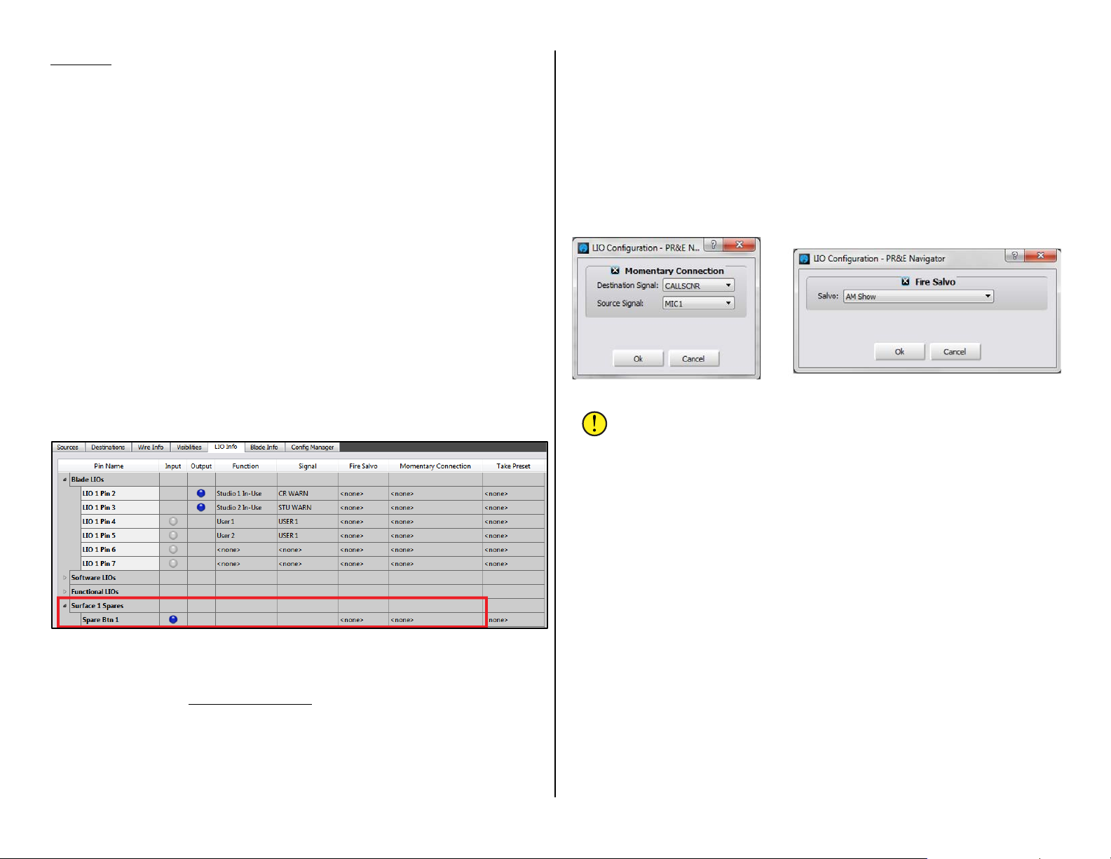
CR WARN destination by click ing its crosspoint. A green square indicates
it’s a logic-only c onnection.
In the example (shown in Figure 3-27 on page 40), when a CR mic
channel is turn ed on, the Logic jack will have a contact closure between
pin 2 (CR WARN) and pin 1 (ground). If a second LIO is assigned to pin 3,
and labeled STU WARN and its Function is set as Studio 2 In-Use, when a
Studio mic chan nel is turned on, they’ll be a c on ta c t clos ure between pin 3
(STU WARN) and pin 1 (ground). These logic outputs are then physically
connected to a hot studio warning interface; to mic ar m lig hts; to a mic
skimmer; etc.
Using the Soft Button
The large white Soft button can be set to man ually trigger exter nal logic
and/or to light up in response from an external logic input, by adding a
new LIO-only Destination, as outlined in the previous s e c tion, using the
Output Function: Switch 1 and/or the Input Function: Switch LED 1. The
logic destination is then connected to the source: Spare01, using the
crosspoint grid, s o it triggers th e outgoing logic and/ or lights up following
the incoming logic.
The Soft button can also be assigned to make a mom e ntary connection
and/or fire a salvo by assignment settings in the Blade > LIO Info tab
(Figure 3-28). The Soft button is labeled as Spare Btn1 and is lis ted u nder
Surface 1 Spares.
this example). C lic king OK closes that dialog box and adds that entry to
the Momentary C onnection column for Spare Btn 1.
Now, while the Soft button is pressed, the board opera tor mic is
switched into the call screener’s speaker. When the Soft button is released
their monitor audio is recon nected to the speakers.
To assign the Sof t b utton to fire a Salv o d ouble-click on <none> in the
Fire Salvo column for Spare Btn 1. The Fire Salvo w indow opens (Figure
3-29, right illustra tion). Check the Fire Salvo checkbox to activate th e
Salvo: drop down list. Choose which salvo to fire then click OK to close the
window. That sa lvo name then appears in the LIO Info window.
Figure 3-29 LIO Dialog Boxes
Note: Even though most users assign the Soft button to perform a
single action, the button c a n be set to do any combination of:
firing a Salvo; making a Momentary Connection; and sending out
an LIO and/or SLIO command. This allows the Soft button to
accomplish very complex actions at the press of the button.
Figure 3-28 Blade > LIO Info tab
To use the Soft bu tton as a momentary ta lk button, first s e t the Soft
Button for the function Momentary/Surface LED (so its button lights up
when pressed) in the DMX Surface Setup
In the LIO Info tab, double-click on <none> in the Momentary
Connection column for Spare Btn 1 to open the dialog box shown in
Figure 3-29, left illustration. Click the checkbox to activate the Sou rce and
Destination sign al selectors. In the example, the source is MIC 1 ( the board
operator mic) an d the destination is a call screener’s output (CALLSCNR in
Buttons page tab.
Creating and Using Associat ed Connections
To create a new A s s ociated Connection, click System > Associate
Connections tab. If any Associated Connections have already been
entered, they will already be listed in the tab, as shown in Figure 3-30 on
page 42.
To add an Associated Connection the Triggered Conne c t ion must first
be defined in the left half of the tab. Click the Add… button to open the
Add Triggered Conne c t ion window where the source-to-destination
trigger connection is selected. In Figure 3-31, on page 42, the left
illustration sh ows that the source is PHONE 1 and th e destination is fader
channel 12 (EMXIn12). Clicking OK in the dialog box adds that c onnection
to the Triggered Connections list ( a s shown in Figure 3-30).
All of the Associate d Connections that will be made in r esponse to that
trigger connection are then def ined on the right side of the tab. Highligh t
your new Triggered Connection then click the Add... button in the
Associated Conn ections side of the window. This opens the Add
Associated Connec t ion window (Figure 3-31, right illus tr a tion) where a
source-to-destination connection, which should be made when the
41

triggered connection is det ec ted, is a ssigned. Note th a t this window has an
additional selection: Lock Override. When checked this causes the sourceto-destination c onnection to be made even when the destination is locked.
If Lock Override is left unchec k ed, the source-to-destination connection is
not made if that destination is lock e d.
Figure 3-30 Associated Connections tab
Associated Connections are most often used to control the bus-minus
connections for c odecs which may be set as visible on multiple fader
channels. For example, if Codec A is set as visible on channels 13 – 16
four Triggered Connections would be setup to monitor for Codec A being
taken on any of those four channels. Each triggered c onnection would
typically have one Associated Con nection created to connect that channel’s
bus-minus to the Codec A output.
console the Co-Host mic is automatically taken on channel 5, and the two
Guest mics are taken on channels 6 and 7. The Studio warning logic is
then connected to EMX Tally.
When the same Host mic is taken on channel 1 on the DMX console, the
Co-Host and Guest mics are connected to channels 2 – 4 on the DMX
console and the DM X Tally is connected to the STU WARN logic output
(which could be on the DMX, on the EMX, or on a Razor or M4IP-USB).
Figure 3-32 Creating Associated Connections for Sharing Talk Studio Mics
Figure 3-31 Associated Connection Dialog Boxes
An example of a more complex Associated Con nection is shown in Figure
3-32 which is used to switch four Talk Studio mics between a DMX console
and an EMX console. When the Host mic is taken on channel 4 on the EMX
42
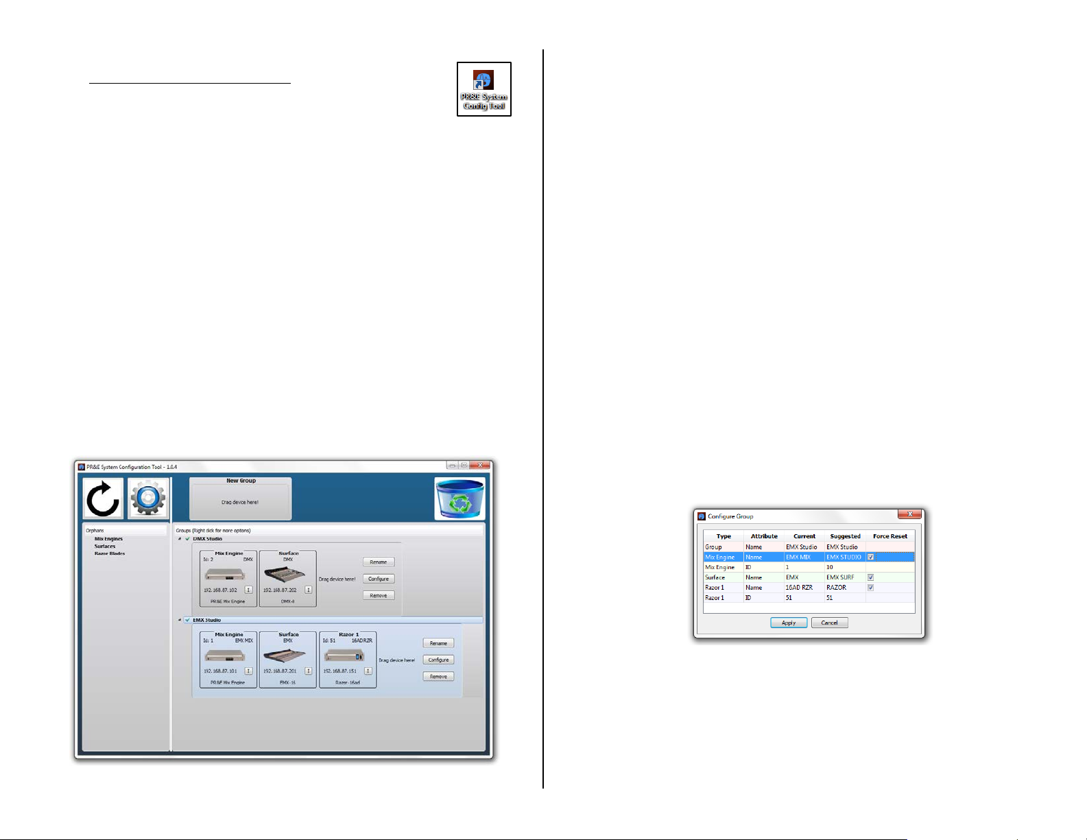
PR&E SYSTEM CONFIGURATION TOOL
The PR&E System Configuration Tool is used to uniquely
configure a new PR&E Mix Engine and Surface, or a new Razor
I/O Interface, so it can be networked with existing DMX and
EMX consoles. I t doe s this by automatica lly editing the default
identify settings on the n ew device (its IP address, device I D, device
name, and signal names) by associating it with either a specific stud io or
room, in the case of a new console, or with a specific host device in the
case of a Razor. The tool can also be used to reset a Mix Engine, Surface,
or Razor back to its factory default settings.
If your new DMX console will always be used as a stand-alone device—
never networked with oth e r D MX or EMX consoles, then you can leave the
DMX set to its default settings an d not have to install this app. However, if
you may network your DMX con s ole with other DMX or EM X consoles in
the future, we recommend u s ing this app to change the default settings on
your console to assign it to a nother IP address, device number, and name.
That way, when a n e w DMX or EMX console is networked with the console
there will be no device conflicts.
Click the desktop icon or start the app from the Start Menu (All
Programs > Whe a tstone PR&E > PR&E Sys tem Configuration Tool).
The app has one screen (Figure 3-33), div ide d into two secti ons:
Orphans and Groups. When a new device is con nected to the network it
shows up in the Orphans section of the screen listing its current IP address
and the type of device.
If a new device does not appear in the Orphan column, click th e Refresh
button (round ar r ow button in the uppe r left) to rescan the network. If no
devices appear in the Orphan colum n or in any Group, click the Settings…
button (the gear icon) to open the app’ s Settings window. Click the
Network Interfac e tab and select the NIC that’s connected to the DMX
system. If it is changed you must restart the app.
An Orphan can be click-dragged from the Orphan column into an
existing group (used when addin g a new Razor). That device then appear s
in that group ready to be configu red. A new Mix Engine and Surface would
be click/dragged up to the New Group box. This crea tes a new Group with
a blank window so the matching Mix Engine or Surface can be click/
dragged into that group.
You can also identify any device by clicking the “I” button in that
device’s window . Doing this on a Sur face causes the PGM select buttons to
blink. On a Razor , a large thumbprint appears in the front p a nel display.
On a Mix Engine the green Route M a s ter a nd Clock Master LEDs blink.
Any configured device can also be click/dragged to the recycle icon
(upper right corner) to return that device back to its factory default
settings. This might be done when an Engine and Surface or a Ra zor are
being repurposed for a new s tudio. This resets the names, its IP address,
and its device ID back to factory d efault settings.
Configuring a Device
When a new Mix Engine and Surface are added to a new gr ou p, they can
be assigned unique network s e ttings so they can be networked with
existing PRE-I P devices. This is done by clicking the Configure button in
that group to open the Configure G r oup window (Figure 3 -34).
Figure 3-34 Configuring a New Device
This window shows the names an d Blade ID number suggested by the
app. If you accept these settings , clicking the Apply bu tton will configure
the Mix Engine an d Surface using these settings. In most cases you’ll wa nt
to edit the suggested entries. This is done by double-clic king on the name
or the ID number. New names can then be type in, or a new ID number
Figure 3-33 PR&E System Configuration Tool
selected from the drop-down list of available ID numbers. Click Apply and
the app will update the device us ing the new names and ID number.
43

SOFTWARE UPDATES
Wheatstone/PR&E may periodica lly issue softwar e r e visions for the DMX
Surface, PR&E Mix Engine, and Razor I/O Interfaces. The DMX Sur fac e
code version is viewed and upda ted u s ing the DMX Surface Setup
Hardware menu (Figure 3-35) . The Engine and Razor code is u pda ted
using PR&E Navigator’s
Version Manager tab (Figure 3-36).
app’s
Surface Code Update
To see the curren t version of code run ning on the DMX Surface, in the
DMX Surface Setup
up window lists in formation about the current code that’s running on the
DMX Surface, including the version number.
The Surface code is downloaded to the admin PC as part of the DMX
Surface Setup
be available to be downloaded s epa r a tely. Click Hardware > Update… to
open a Windows file search window . It opens on the folder h olding the
code downloaded with the Surface Setup
separately, th e n navigate to that folder. The code file will be named:
PRE_DMX_ surface_ X_X_X.rbn with the Xs being the version number
of the new code.
Click Open to upload the new code to the Surface. This action can be
done while the console is actively being used since the c ode is only loaded
into the Surfac e ’s memory. A popup message advises that the Surface
must be rebooted to use the new c ode.
The DMX continues to pass a udio as the Surfa c e is rebooted but, of
course, no Surface controls will be a vailable during the 60 seconds or s o it
takes the Surface to complete rebooting and be ready for use again .
app select the Hardware > Version… menu item. A pop
Figure 3-35 EMX Surface Code Version and Update options
app installation. But updated versions of the code may also
app. If the code was downloaded
Engine & Razor Code Update
The PR&E Mix Engine and Razor c ode is also saved to the admin PC
when the PR&E Navigator
operating system code for th es e devices may also be available to be
downloaded separ a tely from the Navigator
Figure 3-36 PR&E Mix Engine and Razor Code Version and Update options
The code version running on each Blade can be viewed, and the code
can be updated, using the Version Manager tab in P R&E Navigator
3-36). The Software Version colum n lists the code bu ild c urrently runn ing
on each Blade (the PR&E Mix Engine and each Razor I/O Interface). Blades
can be individually update d or they can all be updated s im ultaneously.
Click the Update... button to open a Window s file search w indow, which
opens on the folder PR&E Navigator
with it. If the code file was downloaded separately, then the code file may
be in a “Downloads ” folder so use the file search window to locate the new
code file. The Mix Engine an d R a zor code is in a compressed file named:
DMX_update_ X_X_XX.tgz, with the Xs being the code version number.
Once the code is uploaded to the Bla de( s ) , ea c h Blade must be rebooted
to actually run the updated code. As the updated code is subs equently run
there will be momentary muting or audio changes on the progr a m buses
and monitor outputs so, if possible, the code updat e pr oces s s hould be
done while the console or Razor are not carrying on -air a udio.
app is installed. But updated versions of the
app.
(Figure
uses to save the code downloaded
Note: The PGM buses and monitor ou tputs may momentarily duck
or change levels a s the Surface regains control after re booting.
44

4 – DMX OPERATIONS AND APPLICATIONS
T
his chapter covers DMX Surface operations from the boar d
operator perspec tive. Included is an overview of the control
panel’s featur es and functions ; how to use the DMX to
accomplish specific tasks and functions; how to use the
Advanced Channel Features; and how to use the Razor I/O
Interface’s front panel control and display.
CONSOLE OPERATION
DMX operation is id entical, regardless of which size DMX Surface is being
used—only the number of fader channels differs. Figure 4-1 is an overview
of a DMX Surface listing its main component par ts.
Figure 4-1 DMX Surface Overview
Two fader channel strips are shown in Figure 4-2 on page 46 with a
summary of the fader channel controls and channel displays. An overview
of the monitor controls is shown in Figure 4-4 on page 49. The fir s t
mention of each c ontrol is in Bold in the text.
The Meter Bridge
The left and middle level meters display the Program 1 (PGM 1) and
Program 2 (PGM 2) bus levels respectively. The right meter is a Switched
Meter which can display PGM 3, PGM 4, or an external source (EXT) as
selected using the three Switched Meter Source Se l e ct buttons in the
CR column of the monitor controls. The switched meter may also show cue
levels (when set by engineering during console configuration).
The source assigned to the EXT (E xternal) button is typically also set
during console configura tio n, but it can be changed by press/holding the
EXT button until it starts to blink ( takes about fou r secon ds ) . The left-hand
monitor display switches to show the list of sources available to be
assigned to the EXT button. Rotate the Cue/Source encoder to select a
new external source. Wh en the desired source name is h igh lighted in the
display, click th e Cue/Source enc ode r to a ssign that sourc e to the EXT
button. Note that the EXT button selection is saved as part of an Event so
it could change depending u pon which Event is active.
Timer operation is covered in the Monitor Control Ope r a tion section
beginning on page 48.
Fader Channel Operation
Each fader channel normally has an audio source assigned to it. The
source name is s hown in green in the midd le of each channel display.
When a source has not been set for a channel, NoSource is shown in the
channel display.
Most fader channels have alternate sources, assigned during console
configuration, so that different sources can be “dialed u p a nd taken.” The
alternate source names are listed in alphanumeric order as the channel
encoder (the large knob at the top of each fader channel) is rotated when
the channel is turned off. If the channel encoder is rotated while the
channel is on, a FADER ON message appears in the display.
With the channel off, rotate a channel encoder. That channel’s display
switches to show three sourc e names with the currently selected source
shown highlighted in the middle (shown in the right-hand channel in Figure
4-2 on page 46). Turning the c ontrol Clockwise (CW) moves the
highlighting down through the list of names. Turnin g it counter-clockwise
(CCW) moves back up through the list of names. The list wraps around for
a continuous display. When NoSource is set as visible on the chann e l, it
indicates the list has wrapped aroun d s ince it’s the first name in the list.
To select a new source, highlight its name then press once or “click” the
encoder knob. The new source name then appears in green in the middle
of the display, as shown in the left-hand channel in Figure 4-2 on page 46.
Channel functions can change when a new source is selected since many
channel settings are associated with the audio source rather than with the
channel (like whether the monitors m ute when a channel is turned on).
45

On channels with dedicated
Figure 4-2 Fader Channel Controls
sources like the board oper ator mic,
phone, and media server playback
channels, there may only be one or
two sources shown when the
encoder is rotated. On channels
with sources that are used
periodically (like a CD player or a n
auxiliary stud io input) there might
be a dozen or more alternate
sources available, even though one
source may be “dialed up” on that
channel most of the time.
Typically, the last few faders near
the monitor controls includ e every
system source so that they could go
to air, be recorded, be fed to a
network, or be fed to th e Internet
stream.
Bus Assign Buttons
Each fader channel can be
assigned to any combination of the
program buses using the PGM 1,
PGM 2, PGM 3, and PGM 4
Assign buttons. A lit button
indicates that channel is assigned
to that bus. An unlit button
indicates the cha nnel is not
assigned to that bus.
PGM 1 – PGM 3 operate the
same: all three buses are fed postfader and post-Channel On switch.
In other words, to hear the
channel’s audio on these program
buses the channel must first be
assigned to that bus (PGM 1, PGM
2, and/or PGM 3 buttons lit); the
channel must be turned on; and the
channel fader must be “potted
up,” typically set so its fader knob
aligns with the two Unity Gain
Marks.
PGM 4 differs from the other
program buses because it can be set for pre-Channel On switch operation
(the audio is always connected to that bus) and/or pre-fader operation
(the fader does not affect the s ou r c e’ s level to that bus). These settings
allow the PGM 4 bus to function like a Sen d bus which might be used to
feed an FX unit.
The PGM 4 bus buttons can also be used to control the Off Line or O L
bus, which is used when phone callers and/or remotes are connected to
the console. The PGM 4 bus assign buttons are then used to control which
channels’ audio is returned to the caller or remote while their channel is
off. Using the special features of the PGM 4 / OL bus is covered in more
detail in the nex t s ection (Caller/Remote Operation ).
If no callers, remotes, or FX units are connecte d to the console, the PGM
4 bus would be set to function th e s ame as the other three PGM buses: the
channels feed it post-fader and post-Channel On switch.
For an on-air studio, PGM 1 is typically used to create the on-air signal.
This means that all channels assigned to PGM 1, turned on, and potted up
will feed air. PGM 2 is often used to create a network or Internet stream
feed which requires alternate program elements from what’s going out
over the air.
The PGM 2 and PGM 3 buses may also be used to simultaneously feed
selected channels to recorders, whether to time-shift-record programming
or to do voice-tracking while th e c onsole simultaneously feeds completely
different sourc e m a te r ial to air.
In a production room, PGM 1 is typically connected to the main
production recorder running Adobe Audition or other on-screen editor. If
the console is in a newsroom or a talk s tudio, the PGM 1 outp ut might be
included as a source on a fader channel on the air console to allow the
host to mix the talk studio mics, or the news announcer to go live from the
newsroom while controlling their own mix of NewsBoss playback actualities
and other sounders along with their mic audio.
Caller/Remote Operation
When phone callers and live remotes are used with the DMX, the PGM 4
buttons are used as Off Line bus (OL bus) assignment buttons. The OL bus
is used to create a special “return signal” for each caller and remote while
the caller and remote fader ch a nnels are turned off to allow for hands-free
conversation betw een the board op er ator and the calle r/remote.
Typically, the c aller/remote channel is assigned to cue so the board
operator can hear them. The board operator’s mic channel is assigned to
PGM 4 (e.g., assigned to the OL bus). Typically no other channel is
assigned to PGM 4 so that the caller/remote only hears the board op’s mic.
If there’s a host or producer, their mic may also be assigned to PGM 4 so
the caller or remote c an hear them as w ell.
When the caller/remote is to go live to air, when their channel is turne d
on their return audio automatically switches fr om the OL bus to the PGM 1
bus so they hear everything (minu s their own audio) that’s going to air,
allowing them to interact with guests in the studio or other show elements.
46

When the caller/remote channel is again turned off, their return audio
switches back to the OL bus so the board operator can give cues for a liv e
remote, or get contact inform a tion or say goodbye to a caller.
The return signal going back to the caller/remote is often called an IFB
(Interruptible Fold Back) signal because while the caller or remote listens
to the fold back aud io (typically the OL bus when their channel is off and
PGM 1 when it is on), the board operator c a n interrupt that return signal at
any time by pressing the caller/remote channel’s TB (Talkback) button in
order to give them cues.
Every channel has a TB button but it has no function (even though it
does light while pressed) with channel sources like CD players since the
return signal, which is automatically generated by th e c on s ole, is not
connected to any d estination.
If there is a lot of nois e in the control room ( like during a mor ning zoo
format) “hand’s free” call answering, where the board operator or Host mic
channel is assigned to the OL bus, may not work—or you may n ot want a
caller to hear ev er ything that’s going on in the stu d io! In this case, the
board op mic channel is NOT assigne d to PGM 4/OL. To talk to th e c a lle r ,
press/hold the TB button on the caller channel to selectively talk to them.
Note: Turning the cue speaker up too loud during a hands-free
call can allow the caller’s voice to be picked up by the host mic,
which can cause echoes as their voice gets retu r ned to them
slightly delayed through the hy b r id or codec.
If no channels are assigned to OL (no PGM 4 buttons are lit) then the
caller/remote does not hea r the control room un less t he board operator
presses and holds the caller/remote channel’s TB (Talkback) button.
Although this setup defeats hands-free operation, it ensures control room
conversations are not heard by the caller.
Note that there are two console setup assignments which affect how a
channel’s audio is fed to the PGM 4/OL bus: whether it’s fed Pre Fader
and/or Pre On switch. Since there is no indica tion of how these are
assigned on the Surface, engineering will need to let the board operator s
know how the PGM 4/OL bus is being fed since these settings affect both
regular PGM 4 and Off Line operation.
When the PGM 4/OL bus is mainly used for callers, then the Host Mic and
possibly a produc e r m ic are set to feed the OL bus pre-fader and pre-On
switch for ease of use. Note that if both PGM4 Pre On and PGM4 Pre Fader
are set, any channel source assigned to the PGM 4/OL bus is heard by the
caller or remote—even when that channel is turned off and the fader is
“potted down.”
If PGM4 Pre Fader is not assigned then the channel faders will have to
be “potted up” for the ca lle r /remote to hear channels assigned to the Off
Line bus. If PGM4 Pre On is not selec ted then the chan nel must also be
turned on before the OL bus will get audio. This is a rarely used setting.
Cue
The Cue buttons control whe ther a channel’s pre-fader and pre-on
switch audio is sent to the cue system, which is used to verify the correct
audio is present on a satellite f eed or a remote as well as for hands-free
answering of phone calls. When a Cue button is lit, that channel’s source is
feeding the cue system. If it’s not lit then that channel’s audio source does
not feed the cue system.
The cue goes to a Cue monitor output, whose output level is controlled
by the Cue level control in the CR column of the monitor controls. Cue may
also be auto-switched in to the board operator headphones. Cu e c an be fed
in stereo (the Split Cue button is unlit) or in split mode ( Split Cue button
is lit) which puts cue in the left ear and leaves monitor audio in the right
ear.
Cue can also be set to automatically turn off when a channel is turned
on and can autom a tically turn on wh en the fader is moved to f ull off (both
are console config uration settings set by engineering).
The cue audio may also override th e s elected signal on the switched
meter while active. This is another console setup opti on.
TB (Talkback)
Press/hold the channel TB button to momentarily talk to a caller or
remote regardless of whether it is getting audio from the OL bus (the bus
returned to the caller/remote when their channel is off) or from the base
mix bus (the bus returned to the caller/remote while their channel is on).
Note: While TB is pressed, the return base mix audio (whether OL
or a PGM bus) is cut off to that caller or remote.
For talkback to wor k the console’s talkback destination (DMX
TkBk) must be connected to a source usin g th e PR&E Navigator
Crosspoint Grid. Typically the board operator’s mic input is the
talkback source.
The TB button is nor m a lly only used when the caller/remote is live (their
channel is On) s ince typically the boa r d operator mic is assigned to PGM
4/OL bus and thus will already be heard by the caller/remote w hile their
channel is Off.
Fader Control
The channel faders control the audio level going to th e P GM 1 – PGM 3
buses (and the PGM4/OL bus when the PGM4 Pre Fader option is not
checked, a console setup assignment). The level range goes from full off
(when the fader is set to the
the signal when the fader is at the 0 indication (see Figure 4-2, page 46).
The fader knobs, in an ideal world, should be set so their center line
aligns with the u nity gain marks (the two arrows next to the fader slot). If
a channel is assigned to Cue and to PGM 1, and the fader is set to the
∞ symbol) to adding up to 12 dB of gain to
47
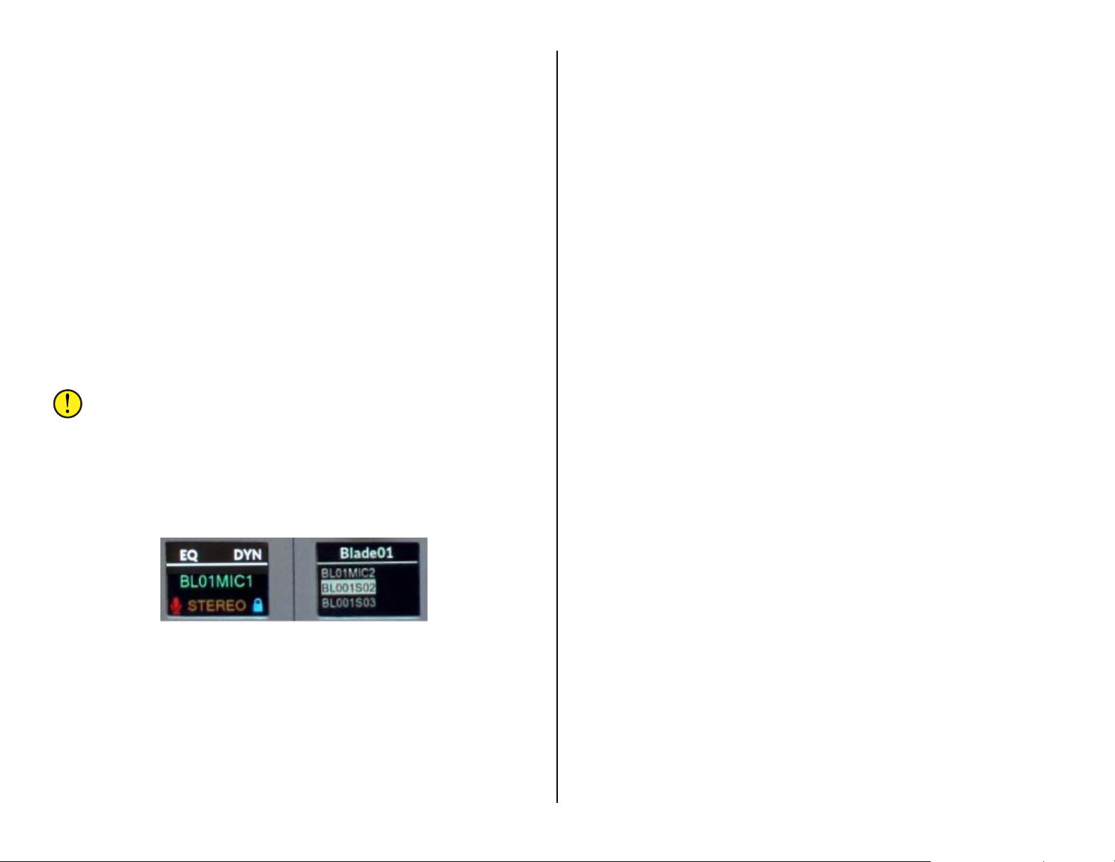
unity gain marks then the switched meter—if it displays cue and the PGM 1
meter levels will be identical.
Channel Control
To turn a channel on, press the On button (Figure 4-2, page 46). A red
LED lights the button to show the ch a nnel is on. To turn th e ch a nnel off,
press the Off button. For most channel sources, a yellow LED ligh ts up
the Off button to indicate the chan nel is off.
Some sources, like media server playback channels, have a logic
command called Ready that allows it to control the Off bu tton’s
illumination to ind ic ate channel status. This fun c tion was originally used
with cart decks to s how their status: no Off button light indicated th e cart
was not ready; a solid Off light indicated the cart was cued and ready to
play; and a winking Off button indicated a cart had already played. Some
automation sy s tems still use this convention to show their playback
channel status.
The channel faders may also be set to automatically control the channel
on and off when they are moved. The channel turns on when the fader is
moved up from full off (the
moved back to full off.
Note: The channel on and off s witches still fun ction normally even
when electronic fader start (EFS) is active.
∞ symbol) and turns off when the fader is
Channel Display
Every channel has a color display to show the channel status. Its normal
display shows the source connected to that channel in green letters in the
middle of the display (name shown in the left channel display in Figure 4-
3). When no source is connected to the channel, NoSource is shown in
green.
In the normal displa y, the channel’ s mode setting is sh own in orange
below the channel source name. The default setting for every channel is
Stereo (a mono signal like a mic or phone c a lle r is automatically fed to
both the left and right channels) but alternate settings, of Left, Right, or
Mono may also be shown.
To either side of the Mode name ar e icons to indicate channel status. On
the right side is a lock indicator to show the channel source’s logic control
state. The lock icon can appear in three colors: Gray indicates th ere is no
control by any channel; Blue indicates that channel fader currently has
control; and an opened Red lock ic on indicates that signal is already active
on another channel fader (whether on this Surface or on another Surface)
and thus this fader channel does not have logic control.
A mic icon is shown to the left of the Mode name when the channel’s
source is a Contr ol Room, Studio, or exte r nal mic. The icon turns red while
the channel is on.
Rotating the Channel Encoder, when the channel is off, changes the
display to show a list of alternate source names (Figure 4-3, right display).
The current source is shown highlighted in the m idd le. Rotating the contro l
clockwise moves the highlighting down the list and rotatin g it counterclockwise moves the highlighting up the list.
Source names are typica lly s hown in alphanumeric order by device
name, but there is a configuration option that allows source names to be
shown by location instead. This alternate setting means that when the
encoder is first rotated, a list of networked devices (Blade01, Blade02,
Blade03, and so on) is shown. Highlight a device then click the channel
encoder to select that device. The list switches to show the source names
on the selected device in a lph a numeric order. Clicking th e Channel
Encoder selects the high lighted name an d r e turns the display to the
normal display where the select ed source name is shown in green.
Figure 4-3 Channel Displays – Normal (left)
and Selecting a New Source (right)
In the normal displa y, shown in the le ft display in Figur e 4-3, the area
above the white line lists whether channel equalization is active (EQ),
whether Dynamics are in use (DYN), and whether Cue is active (CUE).
When a new source is being select ed using the channel encoder, shown in
the right display in Figure 4-3, the device name with the highlighted
source is shown above the white line. In the example the highlighted
source is on Blade01 which is the default na me for the DMX’s Mix Engine.
Monitor Control Operation
The monitor controls on the DMX Surface are identified in Figure 4-4 on
page 49. The controls a re arranged in two columns: the left (CR) column
has the switch ed m ete r s ource selectors an d the control room monitoring
controls; the right (STUDIO) column has the studio mon itor controls along
with the Timer and Event con trols.
CR Column Controls
At the top of this colu m n are three Switched Meter Source select
buttons (PGM 3, PG M 4, and EXT). The lit button indicates which source is
being shown on the switched meter.
Below the three sw itched meter button s is a large white Soft button.
This button is user-defined, so engineering will have to ident ify if that
button is active. Here are a few ex a m p les of what the Soft button can be
used for: as a dum p button and safe indication for the profanity delay; as
48

a talkback button to talk to an external location (a producer, call screener,
or a news room); a s a ring indicator for the hotline phon e; or as a studio
door lock/unloc k control.
Note: A “wild” or temporary source can be feed to the CR
monitors by press/ holding the Cue/Source encoder, for about
three seconds, until a lis t of names appear in the left monitor
display. Rotate the Cue/Sourc e e ncoder to choose the source you
want to monitor by highlighting the name. Click the Cue/Source
encoder to select th at source. Its name then appears in red to
indicate it’s a w ild (i.e. temporary) source. A red name can also
mean that PR&E Navigator
monitor or the source was saved as part of an Event or a Salvo.
was used to connect a source to the CR
Cue
The Cue/Source encoder normally controls the level for an outboard
amplified cue speaker. Adjusting it also affects the cue bar graph, the top
blue/orange bar graph in the left monitor display (Figu re 4-5) with the C
indicator.
Note: The cue speaker(s) are normally set to mute whenever a
control room mic channel is on.
The Cue/Source encoder is a lso used to select the source assigned to the
Switched Meter EXT button and the EXT 1 and EXT 2 CR Monitor Select
buttons. To set a s ource, press/hold the EXT, EXT 1, or EXT 2 button for
about three seconds—until it begins to blink a nd a list of source names
appear in the left monitor display. R ota te the Cue/Source encoder to step
through the vis ible s ource names. When the desired sourc e is highlighted,
click the Cue/Source encoder to assign that source to the blinkin g button.
The blinking EXT button will then turn off.
Figure 4-4 Fader Channel Controls
The six CR Monit or Source Selector buttons (PGM 1, PGM 2, PGM 3,
PGM 4, EXT 1, EXT 2) set which signal feeds the Control Room monitor
speakers and the Control Room headphone jack. The current source is
shown in green in the middle of the left CR Display.
Split Cue
The Split Cue button, when lit and cue is activ e, feeds cue audio to the
left ear and the selected monitor sou r c e is summed into the r ig ht ear of
the operator headphones. When Split Cue is unlit, and cue is active, cue is
sent to both ears (stereo cue) which cuts off the monitor source audio.
Note: Whether or not cue is auto-switched into the board operator
headphones is a console s e tup option, so cue may not affect the
headphones.
49

Monitor Displays
The CR Display (Figure 4-5, left display) shows the current date above
the white line and the name of the cur r e nt CR monitor source in the
middle of the display . The two bar grap hs at the bottom sh ow the Cue and
CR monitor speaker levels.
Figure 4-5 Monitor Displays
The Studio Display (Figure 4-5, righ t display) shows the c urrent time
above the white line a nd the name of th e cu rrent Studio monitor source in
the middle of the display. Th e tw o ba r gra phs at the bottom show the
Studio monitor and the boar d oper a tor headphone levels.
The Control Room monitor s pea k er s a nd the cue speakers are
automatically m uted, and an on-air warning light may be triggered,
whenever a contr ol r oom microphone is turned on. Likewise, when a studio
mic is turned on th e Studio monitors w ill m ute. A red X over th e m onitor
bar graph icon indica tes that output is cur r e ntly being muted.
CR Monitor Speaker Level Control
The CR Monitor Level controls the level of the contr ol r oom monitor
speakers. Its level is shown in the lower blue/orange bar gra ph with the
speaker icon in the left monitor display.
Studio Column Controls
The top of this column has the four very powerful Event buttons, whi c h
are used to first save the four most-commonly used console setups so that
they can quickly be recalled to set up the console for a specific show, a
daypart, or a particular function. Taking an Even t affects the entire DMX
Surface—both fader channels and monitor controls. An Event c an change
channel sources and bus assignments, turn Advanced Channel Features on
or off, set the selected monitor sources, and set the source assigned to
each EXT button in the monitor section .
Board operators c a n normally take Events but they are us ually locked
out from being able to save an Ev ent since engineering typically sets up
and saves the Events before releasing the console for daily use.
The four Event buttons could be used to setup a console for a specific
show and three other common on-air studio functions, or to setup th e
console for four common functions . What daypart, s how, or function ar e
assigned must be identifie d by engineering.
Here’s an example of how the Ev ent buttons could be used:
EVENT 1 – Sets up the console for a multiple mic morning show with
traffic and weather remotes
EVENT 2 – Sets up the console for a live remote show
EVENT 3 – Sets up the console for a single board operator
EVENT 4 – Sets up the console for voice tracking while still feeding air
Taking an Event is a two-step process:
1. Arm the Event. To arm an Event, press/hold the Event button
you want to take. R eleas e the button when it begins blinking (after
about three seconds). The blinking indicates that Ev ent is now
"armed." It can stay armed for an indefinite time so if you mu s t
switch events at a specific time you can arm it at any time prior .
2. Take the Event. At the proper time (like during the last
commercial in a stop set before the new daypart starts), press and
release the blinking Event button. It lights solid to indicate that
Event is now active. All Surface settings get updated within a
couple seconds.
Note: Fader channels that are turned on when the Event is taken
will not be affected by the new Event se ttings. They maintain their
previous settings. After those faders are turned off, rearm and
retake the same Event (press/hold the lit Even t button until it
blinks, then let go, then press it again).
To save an Event, set up the console as required then press/hold an
Event button for about five seconds. The button will beg in blinking after
about three seconds and will then light soli d indicating the E vent settings
have been saved. Any previously saved Event is eras ed.
Note: If you press/hold an Event button and nothing happens that
indicates that both the Take and Save Event functions are locked
out. If the button b eg ins blinking but never lights up solid, that
indicates the Sav e Event function is locked out but th e Take Event
function is ac tive. To cancel taking a n Event press one of the other
Event buttons while one Event button is blinkin g.
Timer Controls
The meter bridge time r is controlled using two button s : Auto Reset and
the S/S (Start/Stop) bu tton.
To manually sta r t the timer, tap the S/ S button. To stop the timer while
it’s running, tap the S/S button. The elapsed time is displayed. Tapping
the S/S button ag a in will start the timer from the elapsed time. T o res et
the timer to 00:00 press/hold the S/S button. If running, the timer resets
to 00:00 and continues cou nting up. If stopped the timer is r es et to 00:00.
50

When Auto Reset is lit, the timer will be r es et to 00:00 and start
counting up when a fader channel, whose source has the Timer Restart
option set, is turned on. Which channel sources have this capability is set
by engineering during c onsole configura tion.
Studio Controls
The EXT button selects a studio monitor source lik e pre-delay. When it
is lit, the source name assigned to the E XT button is shown in green in the
right Monitor Display. The source a ssigned to the EXT button can be
changed as required by press/holding the button (for about three seconds)
until it begins blin king. The right Monitor Display switches to show a list of
sources. Use th e Studio Monitor enc oder to highlight the desired source
then click the en coder to assign that source to the E XT b utton. The EXT
button LED turns off. To select the newly assigned source, tap the EXT
button again. W hen the EXT button is not lit, the normal source for the
studio is DMX PGM 1 .
The Studio Monitor Encoder is normally used to control the level of
the monitor speakers in a separate talk studio, news room, producer
location, call sc r e ener, or other exter nal location (like a performanc e
studio)—anywhere that a microphon e, when connected to the console,
would need monitor speaker m uting when a studio mic is liv e.
The volume of th e studio monitor output from the console is normally
controlled by the S tudio Encoder, bu t when a studio-mounted level control
is used then the Surface’s Studio encoder can be set as inactive (a console
configuration setting).
The Studio monitor s p ea kers are also automatically muted, and a studio
warning light typically triggered, when a studio microphone is turned on.
The board operator c an talk to the studio monitors using the large TB
button located between the Stud io Monitor encoder and right monitor
display. See the TB (Talkback) section on page 47 about setting th e s ou r c e
for talkback audio.
Board Operator Headphone Level
The HDPN encoder c ontrols the volume of the board operat or’s
headphones. Its level is shown in the lower blue/orange bar graph with the
headphone icon in the right monitor display.
Note: A 1/4” TRS headphone jack is located on the right s ide of
the Surface, in-line with the monitor d isplays, for the board
operator headphones. Consumer headphones with 1/8” TRS plugs
required using an 1/8”-to-1/4” TRS adapter. Since the top of most
TRS adapters will end up almost flush with the s ide panel, either
leave a TRS adapter plugged in or require oper a tors to use
headphones with 1/4” TRS plugs or that incorpora te screw-on TRS
adapters so they can easily be unplugged from the 1/ 4” TRS jack.
USING THE ADVANCED CHANNEL FEATURES
Each fader channel has three Advanced Channel Features: Mode;
Panning; and EQ & Dynamics, each of which can be disabled from board
operator access using the Channel Features s ec tion of the DMX Surface
Setup app’s Talent Access page tab (Figure 4-6). In daily use, these
controls are typically disabled (unchecked) for air consoles but are usually
enabled (checked) for production and other non-air consoles
Figure 4-6 Talent Access Controls in Surface Setup App
When an Advanced Channel Feature is active on a channel, and no
channel encoder is touche d for about 20 seconds, that channel’s display
(or displays when EQ & Dynamics is active) automatically return to normal
view. During setup this auto-timeout feature can be disable d which can
simplify setting up the EQ and Dyn amics. To stop the auto-timeout
uncheck the Enabled option in the Timeout section of the Talent Access
page tab. Be sure to recheck this option before releasin g the console for
daily usage.
Mode & Panning
When Allow Mode is checked, double-clicking any channel encoder
(tapping it twice qu ickly) chang es that channel’s d is play to show MODE at
the top of the chan nel display. Rotating the enc oder now steps through the
four audio Modes: LEFT only, RIGHT only, MONO sum, and STEREO.
Double-clicking the encoder, while Mode is active, switches the display
to show PAN, if Allow Panning is checked. Rotating the encoder now pans
the signal from center toward full-left or toward full-right. When Allow
Mode is unchecked, double-clicking a channel encoder brings up PAN
rather than MODE.
51

EQ & Dynamics
If Allow Mode, Allow Panning, and Allow EQ & Dynamics are ch ec k ed,
then double-clicking the encoder while PAN is active opens up the EQ &
Dynamics advanced feature. If neither Allow Mode nor Allow Panning is
checked, then double-clicking a channel encoder immediately opens up the
EQ & Dynamics screens. To exit from the EQ & Dynamics fea ture,
double-click the channel encoder again. The channel displays then return
to their normal view s .
The EQ & Dynamics channel feature takes over all eight channel
displays on a DMX-8. On the DMX-16, when EQ & Dynamics is active on
channel 1 to 8, the displays on channels 1 - 8 show the EQ & Dynamics
screens. When active on channel 9 to 16, the EQ & Dynamics screens are
shown on the channels 9 – 16 displays. The six screens that show EQ and
Dynamics status are shown in Figure 4-7.
Figure 4-7 EQ & Dynamics In/Out Selection Screens
The two other EQ & Dynamics screens—on channels 7 and 8 or on
channels 15 and 16, show a graphic of h ow the EQ or Dynamics s e ttings
affect the audio (in the channel 7 or 15 display) and display a list of the
various EQ and Dynamics control screens in the channel 8 or 16 display,
with the active channel number listed above the white line (Figure 4-8).
Turning the channel 8 or 16 encoder steps through the list of control
screens, updating what’s shown in the other seven EQ & Dynamics
screens.
The channel display for the active channel is also outlined in white to
further identif y which channel’s EQ and Dynamics is being affected. In
Figure 4-8, channel 7 is active, thus Input 7 is shown above the white line
on channel 8 and the graphic display on channel 7 is outlined in white.
Saving & Recalling EQ & Dynamics Settings
EQ & Dynamics are assigned on a channel basis. Each channel’s settings
are saved in the Surface’s memory so the settings are restored if the
console is rebooted or p ower cycled.
When a channel has any of the five types of EQ (the settings shown in
Figure 4-7, screens 1 - 5) set as In instead of Out, EQ is shown above the
white line in that channel’s normal display to indicate that equalization is
active. When Dynamics (Compression and/or Expansion) is set In then
DYN is shown above the wh ite line in that channel’s normal display to
show that Dynamics control is active.
Note: As shipped from the factory, fader channels 1 and 2—
typically used for the Host and Guest mics, have microphone EQ
and Dynamics applied to them, which is why EQ and DYN are
displayed on thos e two channels by d efault.
The EQ & Dynamics settings that are applied to any channel can be
saved to an “EQ configu ration file.” Any previously-saved EQ file can then
be loaded into any channel. Both of thes e functions are done using the
DMX Surface Setup
(Figure 4-9).
app’s EQ Section on the Talent Access page tab
Figure 4-9 Saving & Recalling EQ Configuration Files
Figure 4-8 Active Channel Indications
52
To save the EQ and Dynamics settings from a channel, use the upper
row of EQ controls to s e lect the channel from the drop-down lis t then click
the Pull EQ/Dyn settings from button. A File Save dialog box opens s o you
can name the file (like “hybrid” shown in Figure 4-9). Clicking Save saves
the file with a .dm x_eq suffix to identif y it as an EQ configu r ation file.

To recall a previous ly-saved EQ Config file, select whic h channel you
want to apply the se ttings to using th e lower EQ row chann el s e lect dropdown list then click the Push EQ/Dyn settings to button. A file find dialog
box opens so a saved EQ Config file can be selected to apply to that
channel.
Note: The EQ and Dynamics settings assigned to faders 1 and 2
from the factory are saved in the EQ file: PRE_mic.dmx_eq.
EQ & Dynamics Screens
When any of the EQ controls are active, the next to last EQ & Dynamics
channel display (channel 7 or 15) has an audio frequency graph (Figure 410, left and middle illustrations) which shows the current settings of the
various EQ controls. The EQ graphic show s frequency response from 20 Hz
(left side) to 20 kHz (right side). T he center of the display is roughly 600
Hz since it uses a logarithmic scale. The middle horiz on ta l lin e r epres ents 0
dB of gain and each white horizontal line above or below it r e presents
about 5 dB of level.
Even though the EQ & Dynamics settings are made on a channel-basis,
rather than applied to a particular source, because these settings are
saved as part of the four console Events ( a long with the channel source
and other chann e l a nd monitor settings ) with careful p la nning one can
apply different EQ & Dynamics , Mode, and Panning to specific audio
sources by using Events.
Note: Taking an Event overrides whatever EQ & Dynamics
settings—and mode and pan s etting is currently assigned on each
channel.
different type of display since it graphically shows the ratio between the
incoming audio and the dynamically processed output audio. When
Dynamics is set Out the response line is gray. When Dynamics is set In the
line is orange. The top half of the d is p la y reflects the Com pr e s s or’s
settings while the bottom half reflects the Expander’s settings.
High Pass & Low Pass Filters
The High Pass Filter (HPF) and Low Pass Filter (LPF) can be used
independently on any channel (each can be set In or Out) to narrow the
audio frequency ran ge of that channel’s audio to less than 20 Hz – 20 kH z.
The frequency pass band is shown graphically as the controls are
adjusted: a red line represen ts the HPF or low frequency cutof f while a
blue line represents the LPF or high frequency cutoff.
Adjusting the channel encoder on the channel with the HPF display
(Figure 4-11) adjusts the frequency where th e low er s ounds begin to be
rolled off or atten uated. The contr ol r a nge is 16 Hz to 500 Hz . Audio below
the selected frequency is rolled of f at 24 dB per octave. Au dio above the
selected frequency is n ot affected. The HPF is commonly used to remove
low frequency rumble and sounds emitted by air conditioners, AC line
hum, nearby traffic, foots tep s , cabinet noises being picked up by the mic
arms, etc.
Figure 4-11 High and Low Pass Filter Screens
Figure 4-10 EQ Out, EQ In, and Dynamics Graphic Screens
The four sets of parametric EQ controls are also color-coded. The filter
settings for the HPF and Low EQ settings are in red; the Low-Mid EQ is
shown in orange; the High-Mid EQ setting is shown in green; and the LPF
and High EQ settings are shown in blue.
When the EQ is not active (set Out) lines are shown across the display,
as shown in the left screen in Figure 4-10). When the EQ is active (set In)
then the audio pass band is represented in gray (the middle screen in
Figure 4-10).
When the Compress ion or Expans ion control screens are active the
Dynamics display is shown (right screen in Figure 4-10). It’s a very
Adjusting the channel encoder on the channel with the LPF display
adjusts where the higher frequency or brighter sounds are a tten uated. The
control range is 20 kHz down to 1 kHz. This control can selectively remove
higher frequency sounds like hiss from an air conditioner, chair s queaks,
and other high f r e quency noises without affecting the voice s ound—unless
the control is adjusted below about 5 kHz. Audio a bove the selected
frequency is rolled off at 24 dB per octa ve while audio below that
frequency is not affected.
The HPF and LPF can also be used together to create the classic phone
filter effect on a voice. To do this, a dj ust the HPF to about 300 H z and the
LPF to about 3 kHz . If this setting is saved as an EQ file, it can be loaded
into any channel using the DMX Surface Setup
app’s EQ controls.
Four-Band Parametric Equalization
The four parametric EQs (EQ Lo, EQ Lo Mid, EQ Hi Mid, and EQ Hi) are
all identical in operation and, in fact, have the same set of pa r a meter s a nd
control ranges.
53

The EQ Lo screens are shown in Figure 4-12. Note their red color which
matches the color shown in the EQ Graphic screen. Each parametric EQ
has a FREQ (frequency) control to adjust the c enter-point of that EQ; a BW
(bandwidth) control to adjust the width of frequen c ies being a ffected by
that EQ; and a LEVEL control to set the amount of boost or cut applied to
that equalizer.
These controls are active when EQ is set In and the two Shelf EQs are
set Out. The channel 8 or 16 encoder is used to select between sh owing
EQ Lo (which shows EQ Lo and EQ Lo Mid controls) and EQ Hi (which
shows the EQ Hi Mid and the EQ Hi controls).
Figure 4-12 Parametric EQ Lo and Lo Mid Screens
Each parametric EQ’s center frequency is adjustable from 16.1 Hz up to
20.2 kHz. The bandwidth that each EQ affects is adjustable from 0.20
octaves wide up to 3.00 octaves wide. Each equalizer can boost or cut the
selected frequency band +14 or -14 dB from unity gain in 0. 1 dB steps.
Typically, the parametric equalization is adjusted prior to adding any
compression or expansion since the EQ settings and the compression and
expansion setting s interact with one another’s operation.
EQ Lo Shelf & EQ Hi Shelf
These two filters a r e only active when EQ is set In along with either or
both Shelf’s being set In. When active, the screens for the EQ Lo and/or
EQ Hi are affected. While the Shelf is activ e it assigns a fixed bandwidth so
the BW (Bandwidth) screen is not shown. The FREQ and LEVEL controls
operate the same as for the regular parametric equ a lizer.
The two Lo Shelf c ontrols are used to boost or cut the low fr eq uencies
below the selected frequen c y by the amount set by the level control.
The two Hi Shelf controls are used to boost or cut the high frequencies
above the selected freque ncy by the amount s e t by the level control.
The channel encoder with the EQ Shelf LEVEL screen sets the amount of
boost (up to +14 dB) or cut (up to -14 dB) that’s a pplied. T he channel
encoder with the EQ Shelf FREQ s c r een sets where that shelf ends or
begins. The Lo Sh elf FREQ control adjusts where the low s helf ends, from
20.3 Hz up to 198 Hz . T he Hi Shelf FREQ contr ol a djusts where the high
shelf starts, which can be from 4 kHz up to 20.2 kHz.
Dynamics – Compression and Expansion
When Dynamics is set In the Compressor and Expander functions are
activated. The Compressor ha s five controls, with an orange background,
which affect the overall dynamic range of the audio signal by controlling
the loudest audio levels. The six Expander c ontrols (teal background),
work at the opposite end of the dynamic range, controlling what happens
with very low-level audio sig nals.
Figure 4-13 Compressor Screens
Compression
A Compressor controls the overall loudnes s of an audio signal. A small
amount of compression is often applied to mics and phone callers to “even
out” their overall audio levels. Applying higher levels of compression, a long
with using a high er threshold, allows one to obtain consistent maximum
loudness for “shock jocks” and “in-your-face” commentators.
The compressor in the DMX is a soft knee compressor which means its
operation is less n oticeable—for most settings. Setting the controls to their
extreme settings, to get that “loud and in your face” sound that’s right on
the edge of audio distor tion, can cause audible compression artifacts.
To adjust the Compressor (Figure 4-13 shows the compressor screens),
set the Compressor RATIO to 1.0:1 (no compression) and the Compressor
MAKEUP level to 0.0 dB (no added gain). The Threshold (THRESH) point
sets where the compres s or begins to act upon the audio (which can be
from -40 dB up to +10 dB). A good place to start is 0 dB.
As the audio level goes past the Threshold point the compressor begins
controlling the r atio of the outgoing audio compared to the inc om ing
audio. A RATIO of 1.0:1 (no compression) means the output level tracks
the input level. As the RATIO control is adjusted from 1.0:1 up to the
6.0:1 range you increase the amount of level control over the
compressor’s output. With a 2.0: 1 s etting, when the input rises 10 dB over
the threshold level, the compressor’s output only increases by 5 dB. With a
6.0:1 ration a 10 dB increase in the input audio (past threshold) means
the audio output is only increased by 1.7 dB .
Setting a higher RATIO, like 10:1 up to 20:1, sets the compressor to
function more as a limiter. Typically, with h igh RATIO settings you ’ll set
the THRESH higher since you only wan t to “squash” the very hottes t input
signals so you can maintain the compressor’s output as loud as possible
without overdriving the compress or ’s output and causing distortion further
on in the signal chain. If need be the MAKEUP gain can be a djusted to
compensate for highly compres s ed output levels.
54

The ATTACK contr ol s e ts how fast the comp r essor reacts (from 0.10 mS
up to 330 mS) as the audio raises above the THRESH level. Usually you
want to use the f a stest setting possible, but it really depen d s upon the
audio program since faster settings will be more audible. Using very slow
settings can allow the audio to go way past the threshold point before the
compressor kicks in, either allowing distortion or causing audio “pumping”
when the compress or kicks in and noticeable lowers th e output level.
The RELEASE control sets how fast the compressor “un-compresses” the
audio signal after the audio drops below the THRESH level. It can be s et
from 50 mS up to 3.00 seconds. Again, using settings in the middle of the
ranges allows for the most transparent compression. Using extremely fast
settings will resu lt in a udio “pumping” as the compr es s or is open ed a nd
closed in response to quick audio changes. Again, the type of audio
program being compressed, whether voice, music, ph on e c a ller, remote,
etc., must be tak en into account wh e n s etting the Release.
Expander
The Expander screens a re sh ow n in Figure 4-14. The Expander is an
automatic attenuator controll ed by settings of the RATIO and DEPTH
controls. These allow one to slightly duck or dim the audio to virtually
muting (gating) the input audio once its level fa lls below the THRESH
(threshold) setting. The Expan der is often used to automa tically mute
inactive mics in a talk studio by gating their audio or decrease background
noise on phone ca lls or r e m otes by ducking the audio as it falls below the
THRESH setting.
mics don’t open when other active mics are being used in the studio, but
will still quickly un-gate when someone handles the mic or begin s ta lk ing
into it. Typically, slower HANG and CLOSE times are used so the gating
does not occur during a breath or normal speech pause while a faster
OPEN setting ensures the audio is not “upcut” whe n the m ic is first used.
DMX APPLICATIONS
The DMX console is most often used in an air studio to control the audio
going to a transmitter and/or streaming to the Internet. In almost all
cases, the PGM 1 bus is used to feed the air chain and hence has the air
signal. PGM 2 can simultaneously be used to create a differe nt console mix
for a syndication feed, to feed a recorder or a mic skimmer, or to go to a
line output for a temporary video camera or personal recorder.
When the console is used in an air studio, and there is no ta lk studio
associated with the console, the Studio monitor con tr ols can be
“repurposed” for other us es . One typical use is to control the monitor
source feeding th e g uest headphones in the control room to allow the
board operator to change their own monitor ing source withou t affecting
the guests’ headphone feed. In this case the studio monitor out put would
feed the guest headphones either through Talent Stations (Figur e 4-15) or
a headphone amp system. The studio monitor output would be set to a
fixed level (the Studio Monitor lev e l c ontrol would be inactive) but the
studio monitor con trols would still be used to select the monitor sour c e for
the guest headphones. This allows the board operator to freely switch
between control r oom m onitor sources without affecting the audio going to
the guest headphones. It also giv es the board opera tor the ability to talk
into the guest headphones using th e TB (stu d io talkback) button.
Figure 4-14 Expander Screens
How quickly this ducking/gating occurs and releases, and thus how
noticeable it is, is set by the OPEN (1.00 mS up to 100 mS), HANG ( 0.00
mS up to 1.00 S), and CLOSE (50 m s up to 3.00 S) settings. HANG sets
how long the expander waits, as the audio level passes the THRESH
setting, before eith er opening or closing. CLOSE sets how fast the ducking
or gating occurs and OPEN sets how fast the audio gets u n-ducked or ungated as the audio level goes pas t th e T HESH setting.
The DEPTH contr ol s e ts whether the audio is ducked or ga ted as the
audio level drops past the THRESH setting. At 0.0 dB no duckin g or gating
of the audio occur s. Settings from 10 – 25 dB caus e the signal level to
duck. Higher settings, 25 - 40 dB, c rea te a virtual audio gat e to silence the
audio once its leve l drops below the THRESH setting.
As with the Compres s or , setting the con tr ols toward the end of their
ranges will make the duck ing and gating more audible. For gatin g of
unused mics in a talk studio, you’ll want to adjust the THRESH so that the
Figure 4-15 TS-4H Talent Station
The Studio monitor output could alternately conne c t to a newsroom or to
a sports bullpen tha t d oes not have a c onsole but which goes live to air.
The mics in that room would be set as “studio mics,” so they mute the
studio monitor output while on. T heir monitor sourc e would typically be
“Pre-Delay.” The board oper ator can talk to the ta lent in the new s r oom or
sports studio us ing the TB button. If studio monitor speakers are not
55

required, then the studio output could be used to feed a hea dphone amp.
In this case the mics would not be set as s tudio mics so the S tudio output
would not mute.
Network Origination
Flagship station s for sports teams often need to have a second output
from their main a ir s ig nal to function a s a re gional sports netw or k feed.
This output is typ ic a lly identical to their broadcast signal except it does n ot
have local commercial spots an d liners. It may also require adding specia l
signal tones or other logic.
Creating this sec ondary network is e a s ily done by using PGM 1 as your
main broadcast output and PGM 2 or PGM 3 as your network feed. As long
as the media server channels are setup to consolidate local spots and
station liners on particular channels, then thos e faders can be unassigned
from PGM 2 or PGM 3, whereas the national spots playback fader(s) and
the game liners and the play-by-play remote inputs would be ass ign ed to
both PGM buses.
Production Usage
In a production studio, PGM 1 is typically the main recor d signal for an
in-room PC runnin g P ro Tools
system. If the Wheatstone W NIP audio driver is installed on th at PC, and
that PC is connecte d to the Mix Engine’s Ethernet switch, no analog or
digital audio connection is required s ince the audio would connect over
Ethernet for both r ecording and playback . WNIP audio drivers are available
to support play and record of one stere o c hannel up to twenty-four
channels of stereo playback and stereo record.
®
, Audition®, VoxPro®, or other digital editing
Voice Tracking
Using the DMX to do voice tracking is easily done in a production room
where the mic channel would be as s ign ed to both PGM 1 and PGM 2. No
other inputs on th e console would be ass ig ned to PGM 1, which connects
to the recorder. The channel (or channels) with track playback are
assigned only to PG M 2. The talent then m onitors PGM 2 to hear both the
playback track(s) and their mic.
When voice tracking is done on an on-air console, PGM 2 and PGM 3
would be used to accompl ish the same fu nctionality as in a Production
room since PGM 1 is feeding air. It’s recommended that the talent mic be
assigned to a second “voice tracking mic” fader, which is only assigned to
PGM 2 and PGM 3. No other channels should be assigned to PGM 2, which
is the voice tracking feed to the recorder. The playback audio channel(s)
would be assigned to PGM 3. The talent then monitors PGM 3 to hear track
playback and their mic. If they need to go live to air while voice tracking,
they would use the normal board op mic channel, which would remain
assigned to the PGM 1 air feed.
Callers and Remotes
Basic caller and remote channel operation was c ov ered in th e Caller/
Remote Operation section on page 47. This section presents specific
settings for accomplishing tasks like answerin g the station hot line on the
caller channel to take a song reques t or give the caller the bad news they
are not the contest winner; to recording the caller for later broadcas t
because they ar e the contest winn er; and, in the case of a talk show, to
take the caller live-to-air. These are also applicable to remote channels,
although for the m ost part remotes are used to go live-to-a ir , but they
might also be recorded for later rebr oadcast.
If the callers will n ot go live-to-air the caller channel’s PGM 1 button
should be unassigned. The caller channel’s Cue button should be lit so the
board operator can hear the caller in the cue speakers and in their
headphones. The board operator mic should be assigned to th e PGM4/OL
bus (no other channel should be assigned to PGM 4/OL) so they can carry
on a hands-free conversation.
Recording Callers
If the caller will be recorded, we recommend using headphones and
turning the cue speaker level fully down otherwise the boar d operator’s
mic recording will likely pick up the caller’s audio as well.
Since the DMX does not have a dedicated call record bus like the EMX,
you must be creative to connect a call recorder since you want the host
mic on one chann el and the caller on the other channel. The easiest
method to do this is to dedicate PGM 3 for call recording.
To use the “PGM 3 m ethod” you’ll want to take the host mic on a second
fader channel (so the original ch an nel is still availab le to feed air).
Typically, the mic is also assigned to channel 7 (or 15) and the phone is
assigned to channel 8 (or 16). Assign the mic and phone channels only to
PGM 3—making sure no other channels are assigned to PGM 3. Use PR&E
Navigator to connect PGM 3 to the call recorder output. Use the Advanced
Channel Feature Pan to pan the mic channel fully to the left channel and
pan the phone channel fully to the right channel. The caller audio is now
separated from the talent a udio and each channel of the recording can be
individually ed ited on the call recorder.
The advantage of using the “PGM 3 method” is that it allows the call
recorder to connect via Ethernet, using WNIP drivers, or by using any
stereo analog or dig ital output. It also means the call recorder can easily
be set to record ster eo programming. These “Telco Record” channel
sources and pan settings can be saved as an Event to quickly reset the
console for call recording by recalling that Event.
If you don’t have a spare channel for a second mic, and are using an
analog phone hybrid, then you could use two Y cables, one on the phone
hybrid and the other on the console ou tput that connects to the phone
hybrid. One channel will be the ca ller audio while the other will be the mix-
56

minus going back to the caller (e.g., the talent mic audio) . If the call
recorder’s analog input is not balanced, a balanced-unbalanced balun, or a
matchbox, will need to be used.
Going Live-to-Air
When the caller or r emote will go live-to-air, their PGM 1 and Cue
buttons should be assigne d. When their channel is off the caller/remote
will hear the Off Line bus (any channel assigned to PGM minus their own
channel). Typically, only the board opera tor mic is assigned to PGM 4/OL,
but you may need a producer mic a s s igned as well. This allows the board
operator (and producer) to talk with the caller/r em ote to prepare them for
going live-to-air.
When the caller/remote channel is turned on, their mix-minus audio
switches so they hear everything assigned to PGM 1 (minus their own
audio) so they can interact accordingly. If the board operator needs to talk
to the caller/remote while they are on-air, they press the momentary TB
button on the caller/remote cha nnel to give them cues ( like a break is
coming up). Since this action in te r r upt their return a udio, using TB while
live should be used sparingly (and usually n ot while the caller/rem ote is
talking).
RAZOR I/O INTERFACE
Razor I/O Interf a ces are 1RU rack m ount devices install e d in the studio
and/or TOC (T ech nical Operations C e nter) to connect additional peripheral
equipment with the DMX console and other devices on the PRE-IP network.
Each Razor has eight stereo/16 mono inputs and eight stereo/16 mono
outputs. A Raz or is often used to interc on nect satellite receivers , tuners,
phone hybrids, codecs, internet streamers, air chain processor, and
recorders with the DMX cons ole.
using vertical bar graphs, which just confirm that a signal is present on a
particular input or output and that its level appears “normal.”
The Inputs display, in F igure 4-16, shows normal signal levels where all
of the green and a few yellow seg m ents are lit up. Three inputs (3, 4, an d
7) have no audio.
The Outputs display shows a test tone, set f or the maximum signal level,
being fed to all eight st er eo outputs to light up all meter segments. In
practice, both the Inputs and Outputs levels would appear like the levels
shown in the Inputs display.
Their input signals often appear as sources on DMX fader channels while
their outputs may be c onnected to cons ole PGM buses or to channel busminus signals. If you’re checking for levels, engineering s hould have
supplied a list of th e input and output signals on each Razor so you can
confirm wheth er a s pec ific signal is present since that is the biggest u s e
for the Razor front panel display by a boar d opera tor.
The Razor’s front panel has the same type OLED display and large knob
rotary encoder as used on the DMX fader channels. Rotating the enc oder
switches the front panel display between its four screens: Input Levels;
Output Levels; and two screens displaying technical details on that Razor
(its name, ID#, IP address, sample rate, MAC address, software revision,
and hardware revision). Rotate the encoder to display the four screens
shown in Figure 4-16.
The two screens of interest to board operators are the Inputs and
Outputs screen s . Each shows the s ignal levels for all eight stereo channels.
Unlike the DMX console meters these displays only show average levels
Figure 4-16 Razor Front Panel Displays
57

5 – DMX SERVICE INFORMATION
A
ll DMX consoles are designed to yield many years of
trouble-free 24 / 7 oper ation, which is why there’s no
power switch on the DMX Surface, Mix Engine, Razor I/O
Interface, or M4IP-USB Blade. If any DMX system component does require
service, this section covers h ow to obtain service help, technical
documentation, and replacement parts.
PARTS AND REPAIR SERVICES
There are only a ha ndful of field-replaceable parts on the DMX console,
each of which is listed in this section. Most circuit boards and subassemblies are not readily field-serviceable due to the ex tensive use of
surface-mount componen ts and switching power supplies. It is
recommended that the Mix Engine and Razor be returned to Wheatstone
for repair. The DMX Surface does have some field replaceable par ts .
DMX technical information (User Manual, Quick Guide, software revis ion
information, w ir ing diagrams, a p plic ation notes, and service bulletins) are
always availa ble for downloading f r om the Wheatstone web site:
www.Wheatstone.com. Technica l d oc umentation is available in PDF files
so Acrobat Reader 6.0 or later is required.
Parts Ordering and Repair Services
Replacement parts can be purchased through SCMS Inc (800.438.6040),
the exclusive PR&E distributor in the USA; through a local Wheatstone
distributor in the rest of the world; or by calling Wheatstone support at
252.638.7000 (New Bern, North Carolina, eas t c oast USA time zone ) or
by sending an email to: techsupport@wheatstone.com.
To expedite part ordering, and to ens ure the correct parts are ordered,
use the Wheatstone part number when ordering. Some parts and
assemblies may have long lead times, so order spares accordingly.
Any component or pa r t returned to Wheatstone for service, exc hange, or
credit must have an RA (Return Authorization) tracking number issu e d
prior to their return. Items receiv e d without an RA numb er written on the
shipping label side of the pac kaging may be delayed and subje c t to
additional handling fees.
To contact the Wheats tone/PR&E Technical Sup por t depa r tm ent, to
request an RA number or for installation and other technical support for
the DMX console, call 252.638.7000 (8:30–5:30, east coast time) or send
an email to: techsupport@wheatstone.com.
DMX Parts
Wheatstone # Description or Use
007491 FSI-DMX/EMX (DC Power Coupler for redu ndant
powering of any DMX Surface – also requ ir es a 980064
In-Line DC Supply to supply r edundant power)
007505 DC Cable (16-foot, for DM X-8 Surface)
041390 Control Panel Su bassembly for DMX-8
041391 Control Panel Subassembly f or DMX-16
041394 Complete DMX-8 console (Mix Engine & Surface)
041395 Complete DMX-16 console (Mix Engine & Surface)
041396 DMX-8 expander (separate 8-channel Surface)
044300 Razor 16A with Analog I/O and two mic preamps
044301 Razor 16D with all AES I/O
044302 Razor 16AD with half Analog and half AES I/O
044303 PR&E Mix Engine
250157 Control Surface Ribbon Cable
260005 TRS Headphone Jack (soldered part)
520149 Black Rotary Encoder Knob
520154P Fader Knob
530004 Large White Button Cap (On/Off, Soft, Timer, TB)
530378 Small White Button Cap (bus assign, cue, TB, etc.)
540043 Channel Fader (soldered part)
560002 Rotary Encoder (soldered part)
610029 Plug-in OLED Display
850088P LN-21 Hex Driver (1/16”) for control panel screws
980064 In-Line DC Supply (used with the DMX-16 S urface)
DMX CONSOLE SERVICE
The DMX console contains two primary assemblies: the PR&E Mix
Engine, which has no field-serviceable parts; and the DMX Surface, which
has one assembly, its Control Panel, which can be replaced and possibly
serviced in the field.
The optional Raz or I/O Interfac e, like the PR&E Mix Engine, is not field-
serviceable and should be retur ned to Wheatstone if service is r equired.
58

The DMX Surface can be powered down without affecting the PR&E Mix
Engine’s performanc e although in most ca ses this is more troub le than it is
worth, so it is best to by pass the DMX c onsole if the control pan e l m ust be
serviced. The button settings are maintained when the DMX Surface is
powered down and the PR&E Mix Engine will continue to deliver audio.
When the Surface is powered up after a replac em ent control panel is
plugged in, all fader positions will upda te . So, if the console is active , you
must make sure the new control panel faders are set to similar positions
as on the replaced panel, otherwise there could be large c hanges in
volume when the new control panel powers up.
The board operator headphone jack can also be replaced in the field. It
screws into a thr eaded hole in the low er chassis. The con tr ol p a nel must
be removed to access the headphone jack. Use an adjustable wr ench to
turn the square plastic jac k housing to loosen it then hand unscrew the
jack. Be sure to use shrink tubing over the s older joints on the new jack.
The headphone cable plugs into a keyed 3-terminal P hoenix connec tor
(HDPN) on the network interface board so it can be unplugged when
removing and ins talling a new jack onto the cable.
Tools Required
A standard #1 Phillip s screwdriver is used to remove an d r eplac e the
three screws holding the rear c ov er pa nel on the meter bridge. The hex
head screws, which fasten the control surface, require a 1/16” hex driver.
A very small flat blade screwdriver (like a “Greenie”) is needed to adjust
the mic gain trim pots or to flip the phantom power switc hes on the mic
preamps.
If you are making up your own audio cable s, an RJ45 crimper is required
(and lots of RJ45 plugs). Having a Category cable checker with remo te test
plug, so that already run cables can be easily checked in situ, is also a
must.
Mix Engine Status lights
If the red ERROR LED lights up on the front of the Mix Engine, it
indicates a fault in the Mix Engine’s operation. Although a udio may still be
passing through the Mix Engine and there may be no outward sign of
trouble, the error indicator is saying otherwis e.
To clear the fau lt, try rebooting the Engine using PR&E Navigator (rightclick on the Mix Engine ic on in the System Dock and select Reboot Blade).
If the Mix Engine reboots and the Error LED turns off then the issue was
resolved.
If the Mix Engine reboots and there is no change to the Er r or L ED, the
Mix Engine will have to be power cycled. Th is will cut off all audio through
the device so it will have to be bypassed before power cycling it. Unplug its
AC cord and wait a m inimum of ten seconds, to ensu re pow e r is fully
removed from all internal circuits , before plugging the AC c ord ba c k in.
The Ethernet connectors for network conn ection have two integr al green
LEDs. Both blink to indicate Gigabit op er ation. If on ly one is blinking then
that connection is working at Megabit s peeds. This is O K for the DMX
Surface and for an admin PC which only has only one or two stereo signa ls
going over its Etherne t c onnections.
Swapping the Control Panel
The Surface’s control panel can be swapped while the console is on -air
since audio flows through the Mix Engine not the Surfac e. Of course, you
have no control over the audio while the Surface is off lin e, but it should
take less than five minutes to swap the control panel.
To swap the DMX Surface control panel:
1. Unplug the DC power to the Surf a c e. T his can be done by unplugging
the DC connector on the network interface board (see F ig ure 2-2 on
page 11) or, on a DMX-8 Surface, by unplugging its DC cable at the
Mix Engine. On a DMX-16 Surface, unplug the AC cord on its power
supply.
2. Use a 1/16” hex driver to remove the hex screws from around the
Control Panel (12 on a DMX-8, 18 on a DMX-16).
3. Lift up the front edge of the control panel to unplug the keyed ribbon
cable(s) that connect the control panel to the n e twork interfa c e
board. There is one cable on a DM X-8, two cables on a DMX-16.
4. If the control panel is being replaced “hot” make s ure the faders on
the replacement con trol panel are set to the same positions as on
the original control panel. This is not important if the console is
taken off-air, the faders can be set to fu ll off.
5. Set the replacement control panel onto the rear s upport rail and plug
in the keyed ribbon cable or cables.
6. Set the control panel into place on the chassis and fasten it to the
chassis using the hex screws removed in step 2.
7. Plug in the DC cable to power up the Sur face.
The new control panel will take abou t a m inute to boot up. The same
audio sources, a ssignment button settings, and m onitor settings as the
original panel w ill appear on the replacemen t pa nel. If the faders w er e s et
as on the original pa nel, and the DMX console has continued playing on
air, there will be momentary audio level chan ges as the new Surface takes
control (especially if EQ or Dynamics are active s ince there will be a couple
seconds where the audio switches to flat then switches back to the EQ and
Dynamics settin gs for any channel that is live).
59

APPENDIX A – CREATING A PRE-IP NETWORK
A
Figure A-1 Netgear Switch
ny DMX console can be networked with up to three other
PRE-IP or WNIP-compatible devic es ( P C or audio server,
Razor I/O Interface, M4IP-USB Blade, talent station , etc.)
using the five-port Gigabit switch built into each PR &E Mix
Engine. When additional AoI P devices need to be
networked with your DMX, or if you wa nt to network your
DMX with additiona l EMX and/or DMX consoles, one or mor e AoIP switches
(e.g., a Wheatstone-approved 1GB Ethernet switch) must be used to
support the additi on a l a udio streams propagated over a PRE-IP network.
PR&E MIX ENGINE ETHERNET SWITCH
The PR&E Mix Engine contains a Netgear GS105Ev2 5-port Gigabit
ProSafe Plus Ethernet switch. It was configured at the factory for a sta ndalone DMX studio w ith the PR&E Mix Engine connected to P or t 5 and the
DMX Surface connected to Port 4. Por ts 1 – 3 are available to connect
additional PRE-IP devices like a Razor I/O Interf a ce, a talent station, or a
media server using the WNIP audio driver.
When the DMX console will be networked with additional DMX and EMX
consoles, or if additional AoIP de vices need to connect to the DMX, an
external AoIP switch needs to be added to not only add netw or k ports, but
to also function a s a n “IGMP querier” to control audio streaming across the
network. To connect the DMX switc h to the external AoIP switch, use Port
1 on the built-in sw itc h since that port is designated as the “IGMP
Snooping Static Router Port.”
The built-in Netgear switch configu r a tion should not need to b e c hanged
even when it’s con nected to an extern a l AoIP switch. It is advisable
however, to edit the s witch IP addres s to assign a unique IP to each DMX
switch when creating a PRE-IP network. Doing this will allow you to access
each switch rem ote ly, from the system’s admin PC, using the Netgear
ProSafe Plus Utility (V2.7.2 or later).
You can also view the switch settings on a
stand-alone DMX using a web browser on th e
admin PC. Enter 192.168.87.239 ( the IP
address assigned to each switch at the
factory) into the s earch bar. A log-in window
appears (Figure A-1). The default password
is password. After entering that password
the System Management pa ge is dis pla y ed
(Figure A-2) which shows the switch’s IP
address. To be able to remote into multiple
Login Page
console switches from the system a dmin PC, each Netgear s witch will need
to be assigned a unique IP addres s prior to networking the various DMX
and EMX consoles.
To change the Netgear IP addres s , edit the IP Address entry (high ligh ted
in Figure A-2) then click Apply. We recommend using 192.16 8.87.240,
then .241, and so on, up to .254 as the IP addresses assigned to the Mix
Engine switches. Leave 192.168.87.239 open so if a new PR&E Mix Engine
is networked it can be accessed by the admin PC to edit its default IP
address.
Figure A-2 Netgear Switch System Management Page
Note: Creating an IP address table--whether using an Excel
spreadsheet or one that’s handwritten, is ess ential. The list sh ould
have every device connected to your PRE-IP network: Mix Engin e s ,
Surfaces, Razors, M4IP-USB Blades, PCs, audio servers, talent
stations, SS-8 panels, etc. since every device will be assigned a
unique IP address since a PRE-IP network, like every AoIP
network, does n ot s upport DHCP.
The default IP addresses as s igned to new “factory-fresh” DMX and EMX
consoles and Razors should be reserved so that a new device can be
plugged into the network an d th en assigned a unique IP using the admin
PC. Reserve these IP addresses: 192. 168.87.101 (PR&E Mix Engine);
192.168.87.201 (DMX a nd EMX Surfaces); 192.167.87.50 ( R a zor-16A);
192.167.87.60 (Razor-16 D); and 192.167.87.70 (R a z or -16AD).
60

This allows the PR&E System Configu ration Tool, running on the admin
PC, to be used to assign a new IP address and to setup default signal
names for each new device by simply connecting the new device to the
PRE-IP Ethernet switch. The setup tool assigns a new IP address using the
ID Number you assign to a device in the app. This means that when a new
Mix Engine is set as ID 9, its IP a ddr es s will be set to 192.168.87.109 and
the matching Surface will be set to an I P address of 192.168.87.209.
Razor ID numbers start at 51, which means its IP address is set to
192.168.87.151.
Note: On a very large system (over 39 EMX and DMX consoles),
the IP addresses assigned to th e Mix Engine’s internal Ethernet
switches should not be assigned addresses in the .240 to . 254
range. Rather they could be assigned with the AoIP switches , using
the .1 up .20 range or set to .22 and abov e r a nge (assuming .21 is
assigned to the admin PC).
Media servers and PCs are typically assigned IP addresses starting at
192.168.87.100 and mov in g down, reserving 192.168.87. 21 for the admin
PC. AoIP core and edge switches (talk ed a b out in the Multi-Station
Expansion section) are ty pic a lly a s s igned IPs from 192.168.87.1 u p to
192.168.87.20. Talent stations and other accessories would be assigned IP
addresses above the switches and below the PCs and servers ( e.g., in the
.30 to .70 range).
PRE-IP NETWORK EXPANSION
Here’s an overview of what’s involved in creating a PRE-IP ne twork,
starting with one s tand-alone DMX console and adding one or more AoIP
switches to enable a d ding additional P RE-IP devices.
Ethernet networ k switches wh ic h are compatible with P RE-IP and WNIP
networks are generically called AoIP switches to differentiate them from
the facility’s regular Ethernet switches, used to network facility PCs,
servers, and printers togeth e r . An AoIP switch and an Ethernet switch may
be the same model switch since it’s their configuration settings which
really classify whether the switch is AoIP vs. Ethernet. Thus, the AoIP
switch definition is arbitrary a nd only refers to a switch that’s been
specifically configured for audio streaming.
In most installations this means separate switches are used to “air-gap”
traffic on the A oIP network from the facility’s Ethe r net network. But one
could use one or more la r ge Ethernet switches configu r e d into multiple
VLANs, or virtual networks, to isolate AoIP traffic from the facility’s
Ethernet traffic. Creating VLANs is not covered in this manual since we
whole-heartedly recommend using separate AoIP switches to create your
PRE-IP network. Doing this simplifies switch configuration and will make
future network troubleshooting a whole lot easier.
Creating a Small PRE-IP Network
Once the built-in network switch in the Mix Engin e is f ull, the only way to
add additional PRE-IP or WNIP devices is to add a Wheatstonerecommended AoIP sw itch a nd connect the built-in Mix Engine switch
(using Port 1) to a por t on the AoIP sw itch.
Various Ethernet switches from Cisco and HP have been used in WNIP
systems over the years, but their m odel n umbers change on a regu la r
basis, so it’s best to visit the Wheatstone w eb site, or call Wheatstone tech
support, to get a list of the current recommended model numbers.
One current Cisco switch (as of September, 2018) we can recommend is
the SG-300-series of layer 3 managed switches . Models with eight-ports
up to 48-ports are available. A ny of these can be used to create the PRE IP network on c e it h a s been properly configured for A oIP use.
For a single station facility, which might ha ve an EMX console in an onair studio and a DM X console in a production room along w ith several
Razors and audio s er vers, a small eigh t or te n-port switch should work
well. Two in-room P RE-IP devices (Razor I/O Interface, M4IP-USB Blade,
Talent Stations , VoxPro PC, or aud io s e r ver) can plug into th e built-in
switch in each studio, using Ports 2 and 3, reserving Port 1 to c onnect to
the main AoIP sw itc h, which is typically located in the Tech nical Operations
Center (TOC).
Note: PCs and audio servers must be running W NI P audio driv ers
to play and record audio over their n etwork connection . Audio
drivers, to support from one up to twe nty-four stereo c hannels of
simultaneous playback a nd recording, can be purchased through
any authorized Wheatstone or PR&E dealer.
The eight- or ten-port AoIP switch is typically located in a rack room
along with multipl e Razor I/O Interf a ces and audio play back servers. I t
takes a single CA T5e or CAT6 cable, f r om Port 1 on each stud io’ s switch,
to connect each s tudio to a port on the system’s A oIP switch. The Raz or
Blades and audio s e r vers in TOC then connect to other ports on the main
AoIP switch, also using one CAT5e/ CAT6 cable each.
If the on-air studio has a separate talk studio, you would typically add a
small AoIP switc h in that studio to netw or k that studio’s P RE-IP/WNIP
devices and to connect that studio to the main switch. If there are fou r
mics in the talk studio, an M4IP-USB Blade could be insta lle d s ince it has
four mic preamps along with four USB ports for con necting laptops for
playback or record ing. If a Talent Station is used at eac h mic position, for
mic control and to add a headphone ja c k, then an eight-port sw itc h could
be used in that room.
Since Talent Stations can be powered by POE (Power-Over-Ethernet)
using a switch th a t supports POE is re c om mended for talk stu d ios since
that means all of the talent stations only need a single CAT5 cable
connected to them—n o wall-wart supply required.
61

Multi-Station Network Expansion
When two or more sta tions share a single facility we recommen d you
follow the small PRE-IP network ex pansion model for eac h station where
all of that station ’ s studios conn e c t to one “AoIP Edge Switch” typically
located in that sta tion’s main on -air studio. Each station’s edge switch th en
connects to a “C or e AoIP Network Switch” located in the c entral rack
room/TOC. Depen ding upon how ma ny stations, and how much TOC
equipment is being connected, the Core Network Switch might physically
consist of severa l medium-sized (24-port) network sw itc hes rather than a
single larger 48- or 96-port switch.
If a multiple station facility is bein g pla nned, Wheatstone/PR&E offer s
system configu r ation and system progr a m m ing to create sa lvos, scripting
for programmable buttons , etc. These engineering services are charged on
a per-studio or on a per-hour basis. Other services, including factory proof
of performance as well as on-site commissioning and training are also
available. All of these services can be arr an ged th r ough your PR&E dealer.
Wiring Practices
Since the majority of studio wiring is now using straight-thru category
cables (the generic name for four-pair cabling like CAT 5, CAT5e, and
CAT6), we recommend takin g a dvantage of the various c a tegory c a ble
jacket colors available to differentiate your various system signals. This
not only simplifies installation, it ensures future system troubleshooting
will also be easier.
Here are the cable jacket colors we r ec ommend to carry th e various
system signals:
Orange Blade-to-AoIP switch port cables
Signal Connection Control
Most users have several types of codecs which may be shared between
studios or even between different stations in a cluster. These codecs might
include older ISDN interfaces along with newer Tieline Merlins or Comrex
Accesses, but no matter what type codec is used, one could create
Associated Conn ections to automa tic ally connect a m ix-minus signal to
each codec when it’s taken on a console to simpl ify connecting the codecs.
The downside of doing this with shared codecs is that this can lead to a
user changing the return feed to a codec that’s still actively being used. To
prevent this from oc curring, many users opt to force codec users to
physically go to a rack or a PC, often mounted in a hallway outside TOC,
where they must identify wheth er a c odec they want to use is actively in
use or not, and to then dial up an d connect the codec for their use. This
“Public Codec Rack” is ty p ic ally setup with a touch screen monitor, running
Screenbuilder (a Wheatstone app which is configured using a GUI
interface), which allows users to switch codec routing without the need to
use PR&E Navigator’s Crosspoint grid, or use a system salvo, to switch the
return connections to the codecs .
The Screenbuilder app is a very powerful tool that can be licensed to r un
on multiple PCs. The app uses standardized on-screen elements (faders,
meters, labels, bu ttons, clocks, tim ers and other widgets) to physically
control the PRE-IP network devices. Arranging these on a PC screen allows
one to create custom contr ol panels, and quick-access buttons, for
monitoring an d controlling codecs , for setting up feeds for r ec order s , and
for controlling feeds to Internet streamer s .
Green PC & Media servers-to-AoIP switch port cables
Yellow KVM-over-IP cables
Blue Facility IT Ethernet cables (since they are
probably already in plac e a nd are probably blue!)
White IP phone system cables
Black Audio and logic wiring (Blade I/O to & from
peripheral au dio and logic devices)
Most users have standardized on an automation server company—most
of whom offer WNIP support for SLIO (Software logic I/O) which a PRE-IP
network also su pports. The automa tion servers ar e typically located in the
TOC since it is climate controlled and s e r ver noise is not an is s ue.
KVM IP extenders are available from various vendors, like ADDERLink
(
https://us.adder.com/en/kvm-solutions/extenders), which allow a single
category cable to directly conn e c t a server to a studio-located monitor,
keyboard, and mouse over cable runs of up to 160 feet (48 meters).
62
 Loading...