


D-12 / D-16 / D-32
Digital Control Surfaces
TECHNICAL GUIDE
600 Industrial Drive, New Bern, North Carolina, USA 28562

GENERAL INFORMATION
Introduction
The Wheatstone D-12, D-16, & D-32 are a family of digital television audio control surfaces that are
compact (64 channels in 50 inches) and fully loaded with all the functions and control capability needed by
most television broadcast facilities: 5.1 digital surround plus three stereo masters, a host of mix-minus clean
feed outputs, individual channel bus-minus outputs, 7-band digital equalization, digital dynamic processing,
and integrated routing that can access literally thousands of sources and feed thousands of destinations. In
addition it can be ordered with paging, allowing you to get 48 channels worth of mixing in a 24 channel
footprint. The D-12 gives your operators the added convenience of eight stereo subgroups, eight stereo
auxiliary busses, four additional DCM/MUTE busses, and a full event/memory front panel storage and recall
system that doesn’t require an external computer to operate. The D-16 doubles the stereo auxiliary sends to
16, perfect for those variety shows requiring multiple foldback feeds as well as effects sends. The D-32
doubles the mix-minus busses to 16 in addition to the 16 auxiliary sends. Between the 16 mix-minus busses
and direct mix-minus feed from every input channel, there are no limitations for IFB. And because it’s a live
television console, it has extensive communication capability. If there is a mix, you can talk to it. It even has
twelve programmable talkback buttons.
Designed to integrate flawlessly with the Wheatstone BRIDGE digital audio network router, the D-12, D-16,
& D-32 control surfaces allow you to easily create large or small platform-based systems that are
exceptionally user-friendly and flexible. Wheatstone BRIDGE network cages house all I/O ports and engine
cards, and may be wired in tandem within a single equipment room or interconnected to separate remote
locations by means of fiber-optic or CAT-5 cables to provide single wire studio integration schemes.
Once configured, the system operates entirely independently of external computers. Configuration itself is
intuitive and carried out onsite by means of user-friendly graphic interfaces provided by Wheatstone desktop
software. The system also takes full advantage of Wheatstone’s exclusive VDip configuration software, so
that studio functions (like mutes, fader and timer starts, tally, etc.) are easily accomplished right at your
desktop. Once completed, all settings are retained in non-volatile storage, allowing the entire system to run
independently. Ethernet protocol is built in, providing interface with automation, scheduling, and hardware
controllers as you require.
Page 2

GENERAL INFORMATION
The D-12, D-16, & D-32 digital audio control surfaces are designed for simple drop-in installation
in a countertop. Mainframes are available in a variety of sizes, from the compact 32-position up to
the larger 52-position frames shown below. Cutout dimentions (in inches) are shown in the
drawings below for two of the available frame sizes.
Please consult with Wheatstone Sales for other mainframe sizes and dimensional details.
Control Surface Placement
32.6080
CUTOUT DIMENSIONS
32 INPUT FRAME - 27.5" x 50.75"
52 INPUT FRAME - 27.5" x 82.00"
31.2024
0.9000
3.2410
26.8251
D-12 32 INPUT FRAME
1.000 1.000
53.3400
7.5281
2.4911
D-12 52 INPUT FRAME
31.2024
1.000 1.000
D-12 / July 2006
83.6400
page 3

INPUT PANEL
Input Panel (IS-D12)
Controls and Functions
Each input panel of the D-12 digital audio control
surface has four identical strips representing four input
channels.
Programmable Section
Each input has a programmable encoder, 8 character
display, and switch. The user may map any centrally
located function included in the function “list” to this
rotary knob/display/switch. The function mapped to the
Programmable section is mirrored in the central section
when the input SET button is pressed.
A list of available functions (see table on the page
2-8) is accessed by pressing and holding the Programmable Encoder for 3 seconds. After 3 sec, the user scrolls
through the available functions until the desired function
is displayed, and selects it by pressing the Programmable
switch. The Programmable switch will light if the displayed function is already assigned to the channel, or
otherwise will flash. To change to a new function, repeat
the process.
Programming Example: Setting up a Gain control
knob with Phantom Power switch.
1 - Press an input fader SET button.
2 - Press and HOLD the programmable encoder for 3
sec.
3 - Rotate the encoder through the list until GAIN is
displayed.
4 - Press the Programmable switch.
5 - The current gain setting in dB is displayed.
Rotating the programmable encoder adjusts line or mic
gain depending on the input source. Pressing the programmable switch turns on/off phantom power if the
source is a mic; otherwise the switch is inactive.
D-12 / July 2006
page 4

INPUT PANEL
Standalone Switches
The following switches directly access certain input functions.
DYN - activates dynamics settings stored for the input strip. Use the
SET switch on the strip to access the centralized DYN controls on the
EQD-D12 panel.
EQ - activates equalizer settings stored for the input strip. Use the
SET switch on the strip to access the centralized EQ controls on the
EQD-D12 panel.
SET - press an input’s SET switch to access centralized controls
associated with the input channel strip. Central controls include
PAN/BAL, MODE, EQ, Dynamics, Source Select and IFB output
Routing, Delay, Phase Reverse, and Source Gain.
PAGE - Press PAGE to access the second layer of a channel strip
(essentially another full input channel). Each layer is totally independent.
ON - turns the input channel ON. All Bus assignments mapped as
POST ON feeds will receive audio from the input channel. Certain
logic signals may be mapped.
PFL - puts the input channel’s signal into the PFL (CUE) mix prefader/pre-on, and post gain, EQ, and DYN.
AFL - puts the input channel’s post fader/post ON signal into the
AFL mix.
NOTE: If both AFL and PFL are on, they are summed by default to
the PFL output. This summing option can be defeated if desired in the
OPTIONS text file (see sample file in Appendix 2).
IFB (Interruptible Fold-back)
There is one common IFB bus. Users add any or all input channels
to the bus via the IN switch on each individual channel. The channel’s
IFB encoder adjusts the level of that particular channel’s IFB output
(designated here in as IFBx to indicate the IFB output of channel x).
The IFBx signal may be routed to any physical audio output on the
router by pressing the input channel’s SET switch, then using the
Destination router on the XYE-D12 panel. AFL and TB switches allow
the surface operator to monitor and interrupt the IFB, respectively.
IN - puts the input channel post fader/post ON audio onto the IFB
bus.
IFB encoder – adjusts the output level of the IFBx feed.
TB - momentary switch interrupts the IFB feed with Talkback
audio. Talkback audio may be any source on the router that is crossconnected to the D-12’s TB input.
AFL - puts the IFBx audio into the AFL/SOLO/PFL mix.
D-12 / July 2006
page 5

INPUT PANEL
Source Selection
This section allows the user to select any source visible to its
X controller. A Preset memory location stores a single source signal for
recall via the PRESET switch. The REVERT switch causes the previously
selected input to be recalled. Sources may be taken at any time regard-
less of the input fader ON status.
SOURCE - this encoder (X controller) scrolls through the available
sources. The source list may be limited through the D-12 Visibility –
X Controller settings in the XPoint GUI.
TAKE - press this switch to assign the source displayed in the lower
source window to this input channel strip.
REVERT - press this switch to go back to the previously selected
source. Acts as an A/B source selector that toggles between the PRESET
and the selected source.
PRESET - used to store a source in PRESET memory. Spin the
SOURCES encoder until the desired source is displayed in the CURRENT
PAGE display. Then PRESS and HOLD the PRESET switch until the
PRESET button goes off and the CURRENT PAGE display reverts to the
actual current source. The PRESET source name is shown on the channel’s
LCD display.
ALTERNATE PAGE Display - top display shows the source for the
alternate page (see discussion of PAGE button on page 2-3)
CURRENT PAGE Display - lower display shows the channel strip’s
active source.
D-12 / July 2006
page 6

INPUT PANEL
VU and Gain Reduction Metering
Each input fader has two independent 9-segment LED vertical columns
to provide input signal metering. The top column handles pre-fader post/
gain control signal presence VU metering. The lower column handles Gain
Reduction as determined by the dynamics settings for the input channel
strip, and follows the state of the channel’s DYN switch.
Motorized Fader
The fader controls the channel strip’s signal level to all post fader busses.
The nominal unity gain level is at the -12dB mark on the scale. Note that
EVENT recall includes the fader setting.
NOTE that input channels configured for 5.1 sources have fader knobs
engraved with “5.1”.
Bus Assign LED’s
Each input strip has four sets of LED indicators which display the state
of the channels bus assignments. An illuminated LED indicates:
GROUPS – shows which Groups the input is assigned to: 1 through 8.
MSTR – shows which Masters the input is assigned to; 5.1, S1, S2, and
S3.
DCA – shows which DCA masters the input is assigned to: A, B, C, and
D. If lit, the DCA assign LED(s) will flash if the DCA master is turned OFF
or if the DCA master fader reaches a threshold setting of approximately -60.
MXM – shows which MXM the input is subtracted from. An Xpoint GUI
setting, MXM POLARITY, forces the MXM LED logic to flip. In the
flipped state, lit MXM assign LED’s mean that the channel is ADDED to the
MXM mix.
Channel assignments to these busses are made by first pressing the
channel SET button and then pressing the appropriate ASSIGN button on
the MXM-D12 panel.
D-12 / July 2006
page 7

INPUT PANEL
LCD Displays
Channel Status
The selected input channel status information shows on one of the LCD
displays in the control surface meterbridge. The display show input level,
selected source, channel number, preset source, channel status, gain reduction, and other information.
EQ Status
Indicator
Channel
Status
Dynamics Status Indicator
OVER
(Clipping)
Nominal
Level
Input Level
Bargraph
Gain Reduction
Bargraph
Channel
Number
Input Level
The pre-fader level of the input signal is shown on a different LCD
display by a large vertical bargraph. The level is indicated in dB on a
calibrated scale beside the bargraph. If the channel is stereo, the bargraph
shows the sum of the left and right signals. The bargraph is colored, with
green indicating lower levels and red indicating high levels. The nominal
level position is in the middle of the range at the “0” scale marking, and
shows as a thin blue band in the bargraph. The bargraph itself consists of a
moving “DOT” over a solid “COLUMN” where the “DOT” indicates the
peak value of the signal, and the “COLUMN” indicates the average value.
D-12 / July 2006
page 8

INPUT PANEL
On the D-12 control surface the average value column has been set to VU
timing characteristics. In addition, a bright yellow rectangle will light at
the top of the column if digital “OVER” or clipping is detected.
Nominal Level 0dB = +4dBu analog and -20dBFS digital.
Selected Source
The currently selected source name shows on the Channel Status LCD
display underneath the channel description. This name is the 8-character
name as defined in the Wheatstone Bridge Router configuration.
Preset Source
The currently loaded preset source name shows on the Channel Status
LCD display underneath the AUX SEND information. Once again, this
8-character name is as defined in the Wheatstone Bridge Router.
Channel Status
Various indicators on the Channel Status LCD display will show status
information for the associated channel. Above the level bargraph the
words “ON”, “OFF”, “ON AIR”, or “MUTING” will appear as the
channel status changes. “MUTING” indicates that the channel is turned
ON and has a mute set. “ON AIR” indicates that the channel is ON and the
fader is up. The letters “EQ” will show in the Input Level display if
equalizer functions are active for the channel, and “GR” will appear if
signal dynamics functions (compression, limiting) are engaged.
Channel Number
A large white number shows under the GR meter on the Input Level
display to indicate the channel number.
D-12 / July 2006
page 9

Available Functions T able
INPUT PANEL
Function
Name
UNASSIGN UNASSIGN
GAIN Phantom PowerGain Control Gain in dB units
DELAY mS IN/OUTDelay Control Delay in mS units
DELAY Fr IN/OUTDelay Control Delay in frames
BLEND
WIDTH IN/OUTWidth Control Stereo WidthCenter
MODE MODE SelectPAN/BAL Selected MODECenter
AUX1 (to 8) IN/OUTSend Level AUX x
HPF IN/OUTHPF Freq HPF Frequency
NOTCH IN/OUTNotch Freq Notch Frequency
LPF IN/OUTLPF Freq LPF Frequency
LOW F SHELFLow Band Freq Low Band Frequency
LOW Q SHELFLow Band BW Low Band Q or SHELF
LOW L SHELFLow Band +/- Low Band Level
LOMID F Low Mid Band Freq
LOWMID Q Low Mid Band BW Low Mid Band Q
LOWMID L
HIMID F High Mid Band Freq High Mid Band Frequency
HIMID Q High Mid Band BW High Mid Band Q
HIMID L
HIGH F High Band Freq High Band Frequency
HIGH Q High Band BW High Band Q or SHELF
HIGH L High Band +/- High Band Level
LIM TRSH Limiter THRESH Limiter Threshold
LIM RAT Limiter RATIO Limiter Ratio
LIM ATCK Limiter ATTACK Limiter Attack
LIM REL Limiter RELEASE Limiter Release
LIM GAIN Limiter MAKEUP GAIN Limiter Makeup Gain
GT TRSH Gate THRESH Gate Threshold
GT OPEN Gate OPEN Gate Open
GT HOLD Gate HOLD Gate Hold
GT DPTH Gate DEPTH Gate Depth
TRIM LFE 5.1 LFE Trim 5.1 LFE Trim
TRIM LF 5.1 LT FRONT Trim 5.1 LT FRONT Trim
TRIM CTR 5.1 CENTER Trim 5.1 CENTER Trim
TRIM RF 5.1 RT FRONT Trim 5.1 RT FRONT Trim
TRIM LR 5.1 LT REAR Trim 5.1 LT REAR Trim
TRIM RR 5.1 RT REAR Trim 5.1 RT REAR Trim
LFE LVL 5.1 LFE Level 5.1 LFE Level
LEFT/RGT 5.1 LT/RT 5.1 LT/RT
FNT/REAR 5.1 FRONT/REAR 5.1 FRONT/REAR
SRND/CTR 5.1 SURROUND/CENTER 5.1 SURROUND/CENTER
D-12 / July 2006
Low Mid Band +/-
High Mid Band +/-
Encoder Dobby Switch ON/OFF Display
Blend / CenteredCross-Fader BLEND IN or BLENDOFFCenter
Low Mid Band Frequency
Low Mid Band Level
High Mid Band Level
SHELF
SHELF
SHELF
page 10

MIX-MINUS PANEL
Mix-Minus Panel (MXM-D12)
Controls and Functions
The D-12 digital audio control surface is equipped with one
Mix-Minus Panel.
This panel houses AUX SENDS, MXM MASTER OUTPUTS, and
SUB-GROUP, MASTER, DCA, and MXM ASSIGN.
AUX Sends
There are a total of eight AUX SENDs available
in the D-12 control surface. A brief comment on the
controls is called for before diving into the details.
The column of 8 knobs (“1” through “8”) labeled
MASTERS, and their associated SET and AFL
switches, have a dual-purpose. If the MXM button in
that section is lit, the control operation applies to the
surface’s MXM outputs, which are dealt with later in
this chapter. But if the SEND button is lit, the control
operation applies to the AUX SENDs, which is the
current topic. For the present discussion on AUX
SENDs we assume the SEND button is lit, and we will
freely discuss controls in both the AUX SENDS and
MASTERS sections of the panel without qualifying
which panel section the control being discussed is
located in.
We will begin by explaining the operation for
AUX SEND 1. The same discussion can be applied to
any of the 8 AUX SENDs.
Any surface input channel can feed AUX
SEND 1. To do so, press the SET button on the input
channel, then press the MXM-D12 panel ON button
for AUX 1. If the button is already lit when you press
the channel SET button, then that channel is already
feeding AUX SEND 1.
Channels normally feed the AUX SEND a post
fader signal that follows the channel’s ON button
(post on). If you press the MXM-D12 PRE ON button for AUX 1, that
channel will feed the AUX SEND regardless of its ON button status. In
a similar fashion, the channel can be made to feed a constant signal level
to the AUX SEND regardless of its fader position by pressing the PRE
FDR button. PRE ON and PRE FDR can be used in any combination.
D-12 / July 2006
page 11

MIX-MINUS PANEL
You can set the level of each channel feeding AUX SEND 1
independently. The AUX 1 control affects the signal level to AUX
SEND 1 of the channel that currently has its SET button lit. Thus you
can generate a mix to AUX SEND 1 from several channels if desired.
Once you have the desired channel(s) feeding AUX SEND 1, you
can adjust the output level of AUX SEND 1 by using the AUX
SEND 1 MASTER, the knob labeled “1” in the MASTERS
area. The actual destination that AUX SEND 1 is routed to is
assigned by first pressing the AUX SEND 1 SET button, then
dialing up the desired destination on the DESTINATION
knob on the XYE-D12 panel and pressing the associated
TAKE button.
AUX SEND 1 can be mono or stereo. Press the AUX
SEND 1 button, then press the appropriate MODE button on
the SUR-D12 panel. If AUX SEND 1 is in STEREO mode,
and if the selected channel is in STEREO mode as well, the
AUX 1 control will act as a BAL control if it is pressed down
while being turned. If the selected channel is in MONO, the
pressed action of AUX 1 is as a PAN. If the AUX SEND 1 is
in MONO mode, the AUX 1 knob does nothing if you press
it while turning. NOTE that surround sends are not created.
A surround source will send a desired stereo to a stereo AUX
SEND.
The AUX SEND 1 AFL switch routes a post AUX 1 level control
signal to the SOLO mix.
AUX SEND settings are shown on the LCD displays.
AUX SENDs 2 - 8 work in the same manner as AUX SEND 1.
XYE-D12 Panel
SUR-D12 Panel
D-12 / July 2006
page 12

MIX-MINUS PANEL
MXM Master Outputs
There are a total of eight MXM’s (mix-minuses) available in the D-12
control surface. For this discussion on MXM’s we assume the MXM
button in the MASTERS section of the panel is lit. MXM 1 is discussed but
the remaining MXMs work in the same fashion.
As mentioned in the chapter on the IS-D12 Input panel, channels may
be assigned to an MXM by pressing the channel’s SET button, then
pressing the appropriate MXM ASSIGN button in the BUS ASSIGN
section of this panel. Subgroups may also be assigned to MXMs in a
similar manner.
Global settings may be made in the Options Text file (see Appendix 2)
to determine if the channel assignments to the MXMs are pre or post fade
and pre or post ON. Settings are made individually to each of the 8 MXMs,
but are global in the sense that, once they are made, the settings apply
equally to all MXM sources.
Once you have the desired sources feeding MXM 1, you can adjust its
output level by using MXM 1 MASTER, the knob labeled “1” in the
MASTERS section. The actual destination that MXM 1 is routed to is
assigned by first pressing the MXM 1 SET button (next to the level control,
and, yes, this is the same button
that serves for AUX SEND 1 SET),
then dialing up the desired destination on the DESTINATION knob
on the XYE-D12 panel and pressing the associated TAKE button.
XYE-D12 Panel
switch) routes a post MXM 1 level control signal to the SOLO mix.
The MXM 1 level and output assign are shown on one of the LCD
displays when the MXM 1 SET button is lit.
MXMs 2 - 8 work in the same manner as MXM 1.
The MXM 1 AFL switch (also
known as the AUX SEND 1 AFL
D-12 / July 2006
page 13

MIX-MINUS PANEL
Bus Assign Section
All bus assignment is accomplished through the four sets of
ASSIGN switches, consisting of eight sub-group, four master,
four DCA, and eight mix-minus assign switches. The switches
illuminate to indicate the assign status of the input channel or
group whose SET switch is currently active. Indicator windows
on the input, group, and master panels show the assign status for
each individual source.
Bus assignment is accomplished by first pressing the SET
button on the desired input channel (IS-D12), group (GRP-D12
panel), or master (MSTR-D12 panel). The assign switches
illuminate to show the source’s current bus assignment. Press
required switches to create the desired set of bus assigns. The
local indicators on the IS-D12, GRP-D12 or MSTR-D12 panel
will change to reflect the new bus assignment.
Input channels may be assigned to any group, master, DCA,
or MXM in any combination. The situation is similar for groups,
except that groups may not be assigned to groups. Masters may
be assigned only to DCAs, but in any combination.
Pressing an input fader SET button will activate the bank of
MXM ASSIGN switches and allow the user to assign or minus
an input from each MXM bus. Pressing a switch (1-8) toggles the
input channel assignment to the MXM bus. The Mix-minus
polarity setting, accessed through the XPoint GUI, determines
whether the channel is added to (positive polarity) or subtracted
from (negative polarity) the chosen MXM bus. With positive
polarity setting the LED lights when the signal is added to the
MXM bus. With negative polarity setting the LED lights when
the signal subtracted from the MXM bus. MXM polarity is set
globally for all 8 MXM busses. Appropriate MXM LED indicator on the input panel also lights.
D-12 / July 2006
page 14

EQ / DYNAMICS SECTION
EQ / Dynamics Panel
(EQD-D12)
Controls and Functions
The D-12 digital audio control surface is equipped
with one EQ / Dynamics Panel. This panel houses EQ,
DYNAMICS, PHANTOM POWER, CHANNEL
GAIN, DELAY, and POLARITY sections.
Dynamics Section
This section provides compression, limiting, expansion and gating functions for individual input channels. DSP based dynamics control is simultaneously
available for all input faders and output masters. Dynamics controls are accessible by selecting an input or
master fader SET button. Dynamics may be switched
in/out directly from the input fader and master fader
DYN switches without having to press the SET button.
Dynamics width follows the width of the selected
source (i.e., stereo or 5.1). An integral meterbridge
LCD display draws a real-time composite dynamics
curve based on the compressor/limiter and gate knob
and switch settings. The setting of each knob is shown
in the display. Gain reduction is displayed on a LED
ladder next to each input fader and on the dynamics
LCD meter. The dynamics curve LCD screen also
includes a GR meter.
Settings
D-12 / July 2006
page 15

EQ / DYNAMICS SECTION
Compressor/Limiter
The compressor algorithm used in the D-12
control surface is designed to:
- allow smooth, inaudible, and unobtrusive
level control on uneven sources;
- be able to act as a peak limiter for inadvert-
ent overload control;
- enable deep effects if required.
The compressor section is a compound of
many diverse dynamics elements.
The level detector is a pseudo-RMS averaging type with its own symmetrical-in-time attack-and-release characteristic adjustable between 0.1mS and 330mS (“Attack” control). At the slower
end of its range, by itself it achieves a nouveau-classic “dbx” style syllabicrate level control. As the time-constant is shortened, it becomes progressively shorter in relation to the lower audio frequencies themselves; the
effect is to turn the detector into more of a peak-level detector, necessary
for limiting or wilder effects. A secondary effect at intermediate to fast
attack-times is that low frequencies are peak sensed while high frequencies are average sensed resulting in an effective high-frequency bias (up
to as much as 6dB differential) which helps to mitigate the detrimental
limiting effect of the resulting audio seeming “bottom heavy” normal to
most compressors.
While the overall gain-reduction scheme is “feed-forward”, the heart
of the detector stage itself is a feedback limiter; this allows for this
carefully-contrived loosely-damped servo-loop to permit far more interesting dynamic effects.
The compressor is “soft-knee”, meaning the compression ratio increases slowly with increasing applied level, greatly easing the sonic
transition into full compression; it helps avoid the “snatching” and
“pumping” at threshold that many “hard-knee” dynamics units exhibit.
A full range of controls is available over the compressor’s behavior:
Threshold
The THRES knob sets the level at which the compressor is fully into
compression of whatever ratio is set. This can be set anywhere in the range
of -30dB to +10dB, unless the lower range is limited by the GATE THRES
setting (see below).
Attack
This control determines how quickly (between nominally 0.1mS and
330mS) the compressor reacts to signals. Faster attack times result in
“tighter” and more obvious control; longer attack times lend themselves
well to gentler automatic volume control.
D-12 / July 2006
page 16

EQ / DYNAMICS SECTION
Ratio
This control determines how much the
compressor’s gain is reduced in relation to the
applied signal. For instance, if the ratio is set at
3:1 and the input level above threshold changes
by 12dB, the output level will changed by 4dB.
Normal usage is between approximately 2:1 and
4:1; anything greater than, say, 7:1 may be
considered “limiting”. The ratio can be set anywhere from 1.0:1 to 20.0:1.
Release
This knob determines the nominal time the compressor takes to
recover after excitation (between 50.0mS and 3.0 Seconds). Short
release times make for more intense, denser, obvious processing;
longer release times are better suited to automatic gain control.
Makeup Gain
When fairly deep compression is invoked (large gain reduction) it
can be necessary to increase the compressor’s output level back up to
nominal system signal level; up to 20dB of output gain is available to
allow this.
Gate
The Dynamics section also contains a noise gate, useful for reducing sounds below a certain threshold.
The GATE THRES control determines the signal level at which the
gate operates. This level be anywhere between -60.0dB and +10.0dB.
This setting will determine the minimum available setting of the
LIMITER THRES knob; the LIMITER THRES cannot be set lower
then the GATE THRES.
The OPEN knob determines how quickly the gate opens to allow
signal passage once the threshold is reached. It can be set anywhere in
the range of 0.1mS to 330.0mS. The gate close time is fixed at 200mS.
The DEPTH knob sets the amount of attenuation given to signals
below the GATE THRES setting, and can be adjusted to be between
0dB and 30.0dB.
The HOLD knob determines how long the gate will stay open after
the signal falls below the GATE THRES level before it begins to close,
and can be adjusted between 50.0mS and 3.0 Seconds.
D-12 / July 2006
page 17

EQ / DYNAMICS SECTION
EQ Section
The EQ section consist of a bank of knobs
and switches that operate the equalizer, a four
band, parametric design with sweepable center
frequency, bandwidth, and boost/cut controls.
Shelving curves may be independently selected
for low and high bands. Separate High Pass,
Notch, and Low Pass filters may also be inserted. EQ control is accessible by selecting an
input or master fader SET button. EQ width
follows the width of the selected source (i.e.,
stereo or 5.1). An integral meterbridge LCD
display draws a real-time composite equalization curve based on the knob and switch settings.
Dobbying any boost/cut (+/-) knob will toggle
the parameter between flat and the current value.
To access EQ on an individual input channels, press the appropriate channel’s SET button
and make the desired adjustments in the EQ
Section. To actually place the adjusted EQ in the
signal chain, press the channel’s EQ button in the
IS-D12 panel. The input channel’s EQ button
will light, and its LCD display will show “EQ”.
High-Pass Filter
This is a 24dB/octave variable high-pass filter with Butterworth characteristics, tunable between 16.1Hz and 500Hz, and with a separate in/out switch (“HPF”
switch). The relatively high order of filter is necessary to allow definite
and decisive removal of unwanted low-frequency artifacts (air-conditioning rumble, line hum, traffic or footstep impacts) with minimal
effect on the required program. The display indicates the filter’s
frequency, and the filter may be clicked in and out by way of the IN
switch.
Notch Filter
This 1/10th octave, variable center frequency notch filter is tunable
between 16.1Hz and 20.2KHz. This filter is used to remove specific
audio frequencies, such as 60Hz or 120Hz for an AC power line hum or
buzz, or perhaps a horizontal scanning interference from a monitor. The
display indicates the filter’s center frequency, and the filter may be
clicked in and out by way of the IN switch.
Note: Butterworth Filters
typically yield excellent
flatness, no ripple in the
pass band, and a rounded
amplitude response near
the cutoff frequency.
D-12 / July 2006
page 18

EQ / DYNAMICS SECTION
Low-Pass Filter
This is a 24dB/octave variable low-pass filter with Butterworth
characteristics, tunable between 1KHz and 20.2KHz. This filter is used
to remove unwanted high frequency artifacts (noise, squeaks, etc.) with
minimal effect on the required program. The display indicates the
filter’s frequency, and the filter may be clicked in and out by way of the
IN switch.
Equalizer
This consists of four bands of parametric control used for modifying the sonic qualities of a signal. Each band has +/-14dB of BOOST/
CUT capabilities (+/- knob; “double click” the knob to return to 0.0dB),
sweepable center frequency over the range of 16.1Hz to 20.2kHz, and
with a filter “Q” or sharpness [BW(BandWidth) knob] sweepable
between 0.3 and 5.0. The LOW and HIGH bands also have a switchable
shelving function. The composite effect of any EQ adjustments, as well
as text describing the equalizer settings, is shown on the screen.
D-12 / July 2006
Composite
Curve
Settings
EQ OUTEQ IN
page 19

EQ / DYNAMICS SECTION
Polarity
A pair of switches, one for left and one for right, are provided
to allow for the reversal of absolute phase of the signal path.
Channel Gain
The CHANNEL GAIN level adjusts the input fader’s selected
source gain. Line inputs are adjusted in a -18dB to +12dB range;
mics are adjusted in a +20dB to +80dB range. Relative gain is
shown in its attendant 8-character display.
The input channel’s PROGRAMMABLE level control and
button on the top of the IS-D12 panel can be programmed to duplicate
the gain control function.
Audio Delay
Audio delay is shown in the CHANNEL DELAY display.
Delay is accomplished for inputs, submixes, master mixes, aux
sends, and mix-minuses by means of activating their corresponding SET button and simply dialing in the audio delay. Delay may
be set in milliseconds (0.0 to 667.0) or frames (0.0 to 20.0 in 0.5
frame steps) by means of the MILLI SECS/FRAMES button.
The IN switch inserts the delay on the currently selected input
or output signal.
Delay settings are vitally important, permitting audio time delay adjustments to allow for video processor delays or satellite-to-terrestrial link audio/
video timing discrepancies.
The input channel’s PROGRAMMABLE level control and button
on the top of the IS-D12 panel can be programmed to duplicate the
delay function.
D-12 / July 2006
page 20

SURROUND PANEL
Surround Panel (SUR-D12)
Controls and Functions
The D-12 digital audio control surface is equipped with one SURROUND
Panel. This panel houses 5.1 CHANNEL TRIMS, 5.1 SURROUND, and
MODE sections.
5.1 Channel T rims
This section includes independent rotary level
controls and Solo switches for each component of
a 5.1 signal (i.e. LT FRONT, CENTER, RT
FRONT, LT REAR, RT REAR, and LFE). The
5.1 trims work with surround input faders, the 5.1
master, and the CR1 and CR2 monitors. Trims are
accessed by pressing the input channel or output
mix SET button.
Each rotary trim control allows for +12/-60dB
boost/cut. Dobbying the trim knob will reset it to
0dB. SOLO switches allow for monitoring of each
component.
The 5.1 trims are gain offsets independently
applied to the current gain setting of each component the 5.1 signal. Conversely, the input fader’s
GAIN control will affect all 6 channels equally.
LT FRONT - rotary knob; centered at 0db,
provides +/- 12dB boost/cut.
CENTER - rotary knob; centered at 0db, provides +/- 12dB boost/cut.
RT FRONT - rotary knob; centered at 0db,
provides +/- 12dB boost/cut.
LFE – rotary knob; centered at 0db, provides
+/- 12dB boost/cut.
LT REAR - rotary knob; centered at 0db,
provides +/- 12dB boost/cut.
RT REAR - rotary knob; centered at 0db,
provides +/- 12dB boost/cut.
SOLO Switches – puts the selected component
signal in Solo monitor. This SOLO section assumes the CR is set to SURROUND mode and works a bit differently from
other SOLO switches on the surface.
D-12 / July 2006
page 21

SURROUND PANEL
Each signal is a single channel and effectively mutes all of the CR
output mix channels except for the SOLO’d component. Example, if you
SOLO the CENTER, only the CENTER speaker is heard. If you SOLO
the R-Rear, only the right rear speaker is heard.
Surround Pan System
This section provides a set of controls to pan an
input fader signal anywhere in the 5.1 Mix bus. Input
fader signals may be mono, stereo, or 5.1 signals. The
surround panner is accessed by pressing an input SET
button.
Note: Normally 5.1 source signals are routed to
input faders that have been configured as surround
inputs. Routing a 5.1 signal to a stereo input fader will
get just the L-R front signals.
PROGRAMMING A CHANNEL FOR SURROUND SOUND: Select the channel you with to
program by pressing its SET button. Assign it to the 5.1
destination by means of the ASSIGN switchbank on
the MXM-D12 panel.
The 5.1 SURROUND section will indicate the
current settings of the encoder LT/RT, FRONT/REAR,
SURR/CENTER, and LFE knobs.
The meterbridge display will also show a multicolor graphic representation of this system. The system
can generate 5.1 signals from MONO or STEREO
sources, and can modify the 5.1 signal of existing
5.1 input sources. Double-clicking any of the encoders will return that parameter to its default
setting (for example, LT/RT returns to center).
LT/RT - rotary knob moves the signal left to
right; dobbying the knob centers signal.
FRONT/REAR - rotary knob moves the signal
front to back, dobbying the knob centers signal.
SURR/CENTER - rotary knob controls the
ratio of CENTER imaging. Full left removes signal
from CENTER and is applied to the LT/RT and
FRONT/REAR panner, full right pans signal to
CENTER only.
LFE - rotary knob controls level of signal sent
to subwoofer channel.
MXM-D12 Panel
D-12 / July 2006
page 22

SURROUND PANEL
Mode Section
The mode selector switchbank includes
5.1, STEREO, MONO, LEFT, RIGHT, and
BLEND buttons. When pressed, the switch
will light up to indicate the selected mode and
it will be displayed in the SELECTED CHANNEL LCD display.
Access this section by pressing an input,
subgroup, master, or monitor SET button.
The functions available depend on which
SET button is pressed. PAN and BLEND
rotary controls only work with inputs.
INPUT SET PRESSED:
The PAN/BAL mode knob acts as a balance control in STEREO mode and as a
panpot in MONO, LT-ONLY, and RT-ONLY
modes.
WIDTH - an effect that changes the apparent distance between the speaker - applies to
stereo signals only.
The BLEND mode sends both the left and
right input signals to both the left and right
sides of assigned stereo destinations. The
BLEND knob acts as a cross-fader between
the left and right source channels. Used for
correcting the edited mix of split track sources
like news packages. The voice and “nat”
tracks feed BOTH LT and RT master outputs.
MODE - row of six interlocked switches (only one selected at a time).
Affects which channels of the source signal are passed to the rest of the input
signal path.
5.1 (surround) – sets the input fader to be a surround channel. Only input
fader channels configured in hardware as 5.1 channels may be put in this
mode. Put channel in 5.1 when selecting 5.1 surround sources.
STEREO – selects stereo mode; LT feeds left, right feeds RT; used for
stereo music, normal mixing applications. If a mono source is selected, it will
feed both LT and RT. A 5.1 source will be down-mixed to stereo.
MONO - selects mono mode; If a stereo source is selected it is summed
to mono and reduced by 6dB. A 5.1 source will be down-mixed to mono.
LEFT (left only) – passes only the left channel of a stereo source.
RIGHT (right only) – passes only the right channel of a stereo source.
BLEND – sends the left and right channels to the rotary BLEND control
for cross fading. The output of the BLEND control is summed.
MODE can be reconfigured by pressing any allowable button. In most
cases pressing a disallowed button has no effect. The exception to this is when
you press the BLEND button and BLEND is not a valid choice but STEREO
is; in that case pressing BLEND will automatically select STEREO.
D-12 / July 2006
page 23

SURROUND PANEL
MSTR AUX or MSTR MXM SET BUTTON PRESSED:
Press STEREO, MONO, LEFT, or RIGHT to put the AUX send in
stereo, mono, left only, or right only mode.
MXM’s are always MONO
SUB-GROUPS or STEREO MASTER SET PRESSED:
5.1 master is permanently set to 5.1 mode.
Press STEREO, MONO, LEFT, or RIGHT to put the subgroup or
master in stereo, mono, left only or right only mode.
MONITOR SET PRESSED:
Press 5.1, STEREO, MONO, LEFT, or RIGHT to put the monitor in
surround, stereo, mono, left only or right only mode.
Only the CR1 and CR2 monitor mixes can be 5.1.
D-12 / July 2006
page 24

EVENTS PANEL
Events Panel (XYE-D12)
Controls and Functions
The D-12 digital audio control surface is
equipped with one EVENTS Panel. This panel
contains COPY FUNCTIONS, TEST TONES,
TIMER, PRESET EVENTS, and XY CONTROLLER sections.
Copy Functions Section
This system provides a convenient means of
copying input channel settings (SENDS, EQ/DYN,
ASSIGNS, PAN/MODE, or ALL) and duplicating
them to other input channels. The process involves
choosing a copy type switch first. It will flash.
Copy Type Switches:
COPY SENDS - initiates a copy of AUX send
settings only.
COPY EQ/DYN - initiates a copy of Eq and
dynamics settings only.
COPY ASSIGNS - initiates a copy of bus assigns only (master, group, MXM, & DCA).
COPY PAN/MODE - initiates a copy of PAN
and MODE select settings only.
COPY ALL - copies all settings from the source
fader except Source & Preset.
Choose the desired channel to be copied by
pressing its SET button (IS-D12 panel). The SET
button will then flash in concert with the COPY
button and the PASTE and PASTE ALL buttons
will light. To go into PASTE mode, press the
PASTE button. It will flash, and the COPY and
PASTE ALL buttons will go out. Then press the SET button of the
target module you wish to copy to. It will begin to flash in concert with
the PASTE button, and the TAKE button will light. To accomplish the
copy, press the TAKE button. See the section “To Copy One To All”
for an explanation of the PASTE ALL button.
The UNDO button is used to undo a TAKE copy. Simply press
UNDO and then TAKE to return the modified channel to its pre-TAKE
status. There is only one level of UNDO. If you do a copy operation,
then do another copy operation, then press UNDO to go back to the
status before the last copy, pressing UNDO again will have no effect.
D-12 / July 2006
page 25

EVENTS PANEL
To Copy Groups
It is possible to take a bank of channels and duplicate it to
another channel bank of equal number. Press the COPY button,
then press the desired SET buttons on the source bank. The
COPY button and the source bank SET buttons will flash in
concert. Then press the PASTE button, which will begin flashing; press the desired target channel SET buttons, which will
flash in concert with the PASTE button. To execute, press the
TAKE button.
This function can be used to copy the settings from any
number of channels to an equal size group of channels. The
channels in each group do not have to be consecutive, and
channels within a group can be a mixture from each PAGE if
desired. There can even be overlap; for example, you can choose
to copy from channels 1, 2, and 3 to channels 2, 4, and 5. After
this copy, channels 1 and 3 would not have changed, channel 2
would be set as channel 1 had been, channel 4 would be set as
channel 2 had been, and channel 5 would be set as channel 3 had been.
When selecting channels for the COPY and PASTE sets, the order in
which you press the buttons matters. For example, if you selected, in order,
channels 1, 2, 4 and 3 for COPY, and then selected, in order, channels 5,
7, 6, and 8 for PASTE, the end result would be that channel 5 would have
channel 1 settings, channel 6 would have channel 4 settings, channel 7
would have channel 2 settings, and channel 8 would have channel 3
settings. Not that this is something you would necessarily want to do, but
that’s what would happen. To reiterate, order matters when selecting the
COPY and PASTE sets.
If the size of the COPY and PASTE groups are different, TAKE will
not effect the change, except for the special case of Copy One and Paste
Many, described next.
To Copy One and Paste Many
Press the COPY button, and then the desired source channel SET
button; both will flash in concert. Then press the PASTE button and the
target channel SET buttons, which will flash in concert with the PASTE
button. To execute, press the TAKE button.
To Copy One To All
Press the COPY button, and then the desired source channel SET
button; both will flash in concert. Then press PASTE ALL, which will
commence flashing. To execute the global paste, press TAKE.
NOTE: If the TAKE button is not pressed within a timeout period of
10 seconds, the entire copy/paste operation will cancel out.
D-12 / July 2006
page 26

EVENTS PANEL
T est Tones Section
The TEST TONES section provides adjustable frequency test signals, a pink noise source, and a stereo ID
tones source.
The multi function oscillator may be assigned to any
mix bus output or input fader. Press the SET button on
the input or mix bus output to begin.
Operate as follows: The encoder knob operates as
both a frequency knob and a level control knob. By
pressing the FREQ button, the encoder will now adjust
the oscillator frequency designated in the TEST TONES
display. Its level can then be adjusted by pressing the LEVEL button
and using the encoder to adjust the level as displayed in the TEST
TONES display. If a pink noise is desired, press the PINK button and
adjust its level by pressing the LEVEL button. For STEREO ID tones,
press the STEREO ID TONES button and adjust the level by pressing
the LEVEL button. The test tone destination is chosen by pressing the
SET button at the desired destination location and then the ASSIGN
button in the test tone section. To use any of the test tones, press the ON
button. When it is lit the selected test tone is available; when not lit the
tones are off.
Frequency Select Switches:
STEREO ID TONES - generates 440Hz on the left channel and
1kHz on the right channel. The TEST TONES display shows both
frequencies.
PINK - generates pink noise on both channels. The TEST TONES
display shows PinkNoiz.
FREQ - defaults to 440Hz; the rotary encoder adjust the frequency
in the range of 20Hz to 20kHz and updates the display.
LEVEL Switch - puts encoder and display in level setting mode.
Default is -20dBFS. Encoder sweeps in 1dB steps in a range from
0dBFS down to OFF. Dobbying the encoder sets a nominal -20dBFS
level.
ASSIGN Switch - assigns the oscillator to the selected mix output
or input fader.
ON Switch - turns the oscillator ON.
D-12 / July 2006
page 27

EVENTS PANEL
Timer Section
The control surface timer is provided with an AUTORESTART function so programmed (via GUI) input
modules can automatically reset the timer display (located on the button of the MASTERS LCD screen) to
zero and start a new count (if the timer is currently
running), allowing the announcer to easily track his own
pace.
The S/S (start/stop) button halts the timer, holds the last count, and
then restarts and accumulates the count when depressed again
for compiling tapes of desired duration.
RESET has a dual-mode capability:
- if you depress it while the timer is counting, the display will
instantly reset to zero and start a fresh count;
- if the timer is already stopped, depressing this button will reset the
timer to zero, where it will hold until start is pressed.
The HOLD button allows you to hold the display for a longer
viewing duration, while still allowing the counter to continue in the
background. Releasing the button will then display the current count.
—
perfect
Time of Day Clock
The MASTER LCD screen includes the display of a time of day
clock. To set the time on this clock you run a Wheatstone utility
program, WSTimeSet.exe, on a network computer. The program
allows you to set the clocks on multiple control surfaces by specifying
the IP addresses of the control surfaces in a list. A single command then
updates all specified clocks. Program options allow auto updating at
midnight or at the top of the hour. See Appendix 1 for details.
Preset Events Section
This section provides a means for storage and
retrieval of control surface settings, and naming
those settings as “events”. In this manner complete
configuration and setting information that is used
repeatedly (for example, morning show) can be
saved and recalled. Event names may be re-titled
by the user. Up to 99 different events can be stored.
A special DEFAULT event stores a user defined
setup. Events may be triggered by the PROGRAMMABLE buttons on the IS-D12 panel.
Storing an Event
When an event is stored, all of the control surface’s current settings
are saved and will be recalled when that event is executed through the
TAKE command. To create a new event from current control surface
D-12 / July 2006
page 28

EVENTS PANEL
settings, hit the NEW button, and then hit the
SAVE button. To overwrite an existing event
with the current settings, turn the PREVIEW
SCROLL knob until the desired event is displayed in the EVENT window, then quickly press
MODIFY, then SAVE.
Taking an Event
Rotate the PREVIEW SCROLL encoder until
the desired event is shown in the EVENT display.
To prevent accidental takes, the ARM button must be pressed to arm the
function. The TAKE button will now flash indicating that the panel is
ready to act on a take. Then press the TAKE button to execute the EVENT.
Undoing an Event
To recover from a premature or erroneous EVENT take, press the
ARM and UNDO buttons. This will return the system to its status prior to
the last take, with the last program event being once again the current
program event, and the last preview event (the one just taken) becoming
the preview event once again. There is only one level of undo. If undo has
been done and a subsequent take has not been done, pressing the undo
button again will do nothing.
Modifying the Currently Selected Event
It is presumed an event has already been executed on the control
surface. Modifications to that event can be accomplished by simply
adjusting the controls and switches as desired and then pressing the
MODIFY button, then the SAVE button. In this way the modified event
will overwrite the old event setting and be saved, with the same name, in
its place.
Deleting an Event
Rotate the PREVIEW SCROLL encoder until the Event to be deleted
is shown in the EVENT display. Press the Modify button, then press the
PREVIEW SCROLL knob; the display will ask “DELETE?”. Press the
TAKE button to delete the previously displayed Event. Do nothing and
Delete mode will time out after approximately 7 seconds. Deleted Events
may NOT be restored.
Previewing an Event
Rotate the PREVIEW SCROLL encoder and available EVENT names
will be shown in the 8-character EVENT display. When the desired event
is shown in the display, press the ARM button, then press the PREVIEW
button. This will cause the entire control surface to display all settings
associated with that event, without disturbing the current operative event.
The preview status will be indicated by illumination of the PREVIEW
D-12 / July 2006
page 29

EVENTS PANEL
button and flashing of all source and destination
displays, to remind the operator that these would
be the intended settings when the change is made.
Pressing the PREVIEW button a second time will
cancel the preview. It should be noted that no
audio signals are changed in any way by the
preview feature.
Event Default Button
This control allows rapid access to a default or
home control surface setting. Push it, and the TAKE button in the Preview
section will flash. Hit the TAKE button and the default setting will be
executed.
Establishing the Default Setting
This setting would normally be set only once. For example, it may be
desirable to have all controls set to zero, or everything programmed to
typical nominal settings. To establish the default setting, adjust all the
control surface controls to their desired settings, press the MODIFY button
and then the DEFAULT button. The default setting is stored.
Naming an Event
When events are saved, they receive a default event designation
number. This way events can be saved quickly without having to name
them. However, an event may be custom named when saved, or at a later
time. To rename the displayed event, press the ALPHA SCROLL knob.
The CURSOR LT and CURSOR RT buttons will light and the cursor,
indicated by a flashing character, will be at the beginning of the name. Also,
the SAVE button will begin to flash. At any time you can use CURSOR LT
and CURSOR RT to move to a character you want to change. Once the
cursor is at the desired character, rotate the ALPHA SCROLL encoder until
the desired new character is displayed. Once all desired characters have
been changed, simply press SAVE to save your changes. The event is stored
with the desired name. At any time you can cancel the name edit by pressing
the ALPHA SCROLL knob. Also, if you stop making name changes but fail
to press the SAVE button, the name edit process will automatically cancel
after a delay of several seconds.
Control Modes
The D-12 control surface is operated in one of three modes. In Administrator mode access is allowed to all surface functions. In User mode a
limited set of user functions is allowed. The set of functions allowed in User
mode is set independently for each console using the Bridge XPoint
software (see the Bridge Router manual for details). The third mode, Guest,
blocks out MXM level, MXM assign, Event takes, and visibility changes
from being controlled by the surface.
D-12 / July 2006
page 30
EVENTS PANEL
To change the control mode, begin by pressing and holding the
PREVIEW SCROLL knob until the display reads “Admin” and the TAKE
button lights (if the surface is currently in Admin mode the ARM button will
also light). Turn PREVIEW SCROLL until the desired new mode (Admin,
User, or Guest) is showing in the display and press TAKE. Turn PREVIEW
SCROLL again to select the first digit of the password. Default passwords,
which may be changed in XPoint, are “1234” for Admin, “2222” for User,
and “0000” for Guest. After dialing up the first character of the password,
press TAKE. Then dial up the second digit. Continue this procedure until
the four characters have been entered. Upon pressing TAKE after entering
the fourth character, the display will read “Okay...” if you were successful
and “Sorry...” if you were not. When finished, turn PREVIEW SCROLL
until the display reads “<<Exit” and press TAKE to finish the mode select
operation.
The ARM button lights as you select the mode that the surface is
currently in. If you press TAKE when displaying the current mode, the
display will switch to “Okay...” and you will not need to enter the password.
If you stop partway through the procedure, the mode selection process will
time out after about 15 seconds.
Once a given control mode is selected for a surface, that setting will
persist through a power cycle or surface reset.
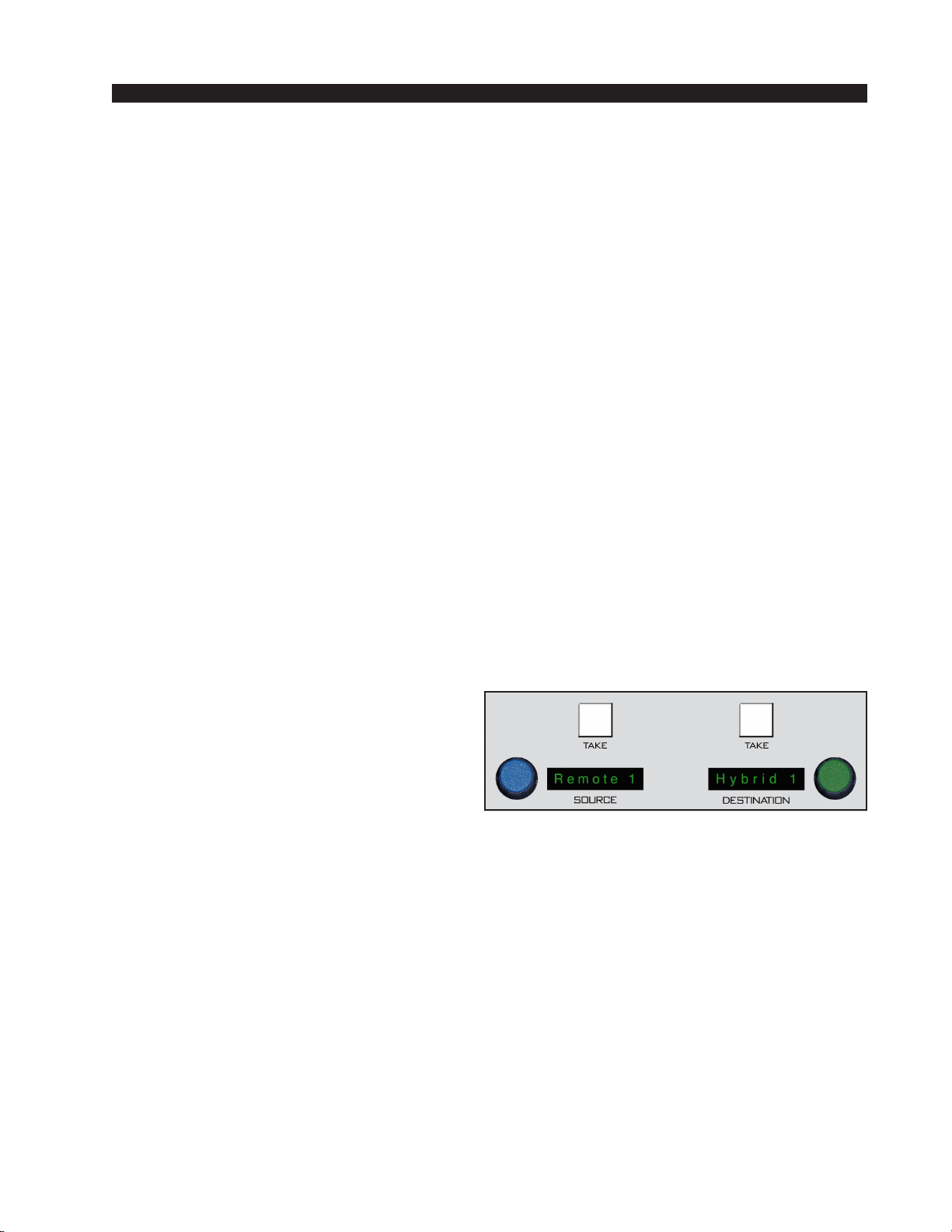
Routing (XY Controller) Section
This section is a multi-use X-Y controller. Rotary knobs are provided
for selecting Sources and Destinations. TAKE buttons are provided for
both sources and destinations.
The information displayed in the eight
character SOURCE and DESTINATION
windows depends on which SET button is
pressed. Signal source and destination visibility is set in the XPoint GUI. Dobby the
DESTINATION knob to step through a list
of routes where the mixer signal is routed to
multiple destinations.
Control variations:
Input SET switch pressed:
SOURCE acts as source selector for input fader.
DESTINATION controls IFB (BUS MINUS) routing.
AUXx master SET switch pressed (MSTR SEND pressed):
SOURCE - not used
DESTINATION – used to route AUX bus to an output.
MXMx Master SET switch pressed (MSTR MXM pressed):
SOURCE – displays/routes Confidence feed source.
DESTINATION – used to route MXM x bus to an output.
D-12 / July 2006
page 31

EVENTS PANEL
Group or Master SET button pressed -
SOURCE - not used
DESTINATION – used to route Group or Master mix to an output.
Monitor SET button pressed -
SOURCE - displays/routes monitor EXT source.
DESTINATION – used to route monitor mix to an output.
Selecting Input Channel Sources
The operator designates the desired input channel by pressing its
SET button in the Input section. Its current input source is shown in the
SOURCE display. Input channel meterbridge LCD displays will
mirror that same information. A different input source may be chosen
by rotating the SOURCE knob. When the desired source is shown in the
SOURCE display, pressing the TAKE button will execute the take
command on the downstroke, and the new input will be shown in the
SOURCE display and in the meterbridge LCD display. This function
operates the same as the SOURCE knob on the input panels. To remove
the input source from the input channel and leave nothing connected
TAKE the source named “NOSOURCE”.
Selecting Output Mix Destinations
When a SET button on an output mix channel (i.e., any of the auxes,
monitors, or MXM masters) is pressed, its most current destination will
be shown in the DESTINATION display. A mix is capable of being
sent to one or many outputs. To see all the destinations that the mix
feeds, rotate the DESTINATION knob. If the mix doesn’t feed the
displayed destination the TAKE button will light. You may also
“dobby” the DESTINATION knob to step through all of the currently
routed destinations.
EXAMPLE: An example might be a MXM feed routed to several listeners
participating in the program, or an AUD bus routed to multiple recording
devices.
Changing Output Mix Destinations
Rotate the DESTINATION knob until the desired destination is
shown in the DESTINATION display. When the knob is rotated, the
TAKE button will light if the displayed destination is not being fed by
the mix. If the operator wishes to add the destination shown, press the
TAKE button to execute the command and the new destination will
become the current destination, shown in available displays elsewhere
on the control surface. Disallowed destinations (established in the
configuration software) will not be shown.
Tip: The CR monitor SPKR
A and SPKR B buttons act
as SET buttons to program
the SPKR A and SPKR B
destination(s) separately.
Tip: DOBBY (pronounce
dah-bee) - means to quickly
press and release an encoder knob.
D-12 / July 2006
page 32

MONITOR PANEL
Monitor Panel (MON-D12)
Controls and Functions
The D-12 digital audio control surface is equipped with one MONITOR Panel. This panel houses MONITORS, AFL & PFL levels,
SWITCHED METERS, and CONFIDENCE FEED sections.
PFL(Cue)/AFL(Solo) Section
The PFL(CUE) and AFL(SOLO) master level
controls are located on the left top section of the
MONITOR panel.
These rotary controls provide volume control of
the PFL (CUE) and AFL mixes respectively. PFL is
“pre-fader listen “, AFL is “after fader listen”. Monitors may optionally be interrupted with the PFL/AFL
signal. This interrupt action is defined in the
OPTIONS.txt file stored on the D-12 surface (see
sample in Appendix 2). The default is no interrupt.
Input faders put into the PFL mix are summed and
output on a PFL mix signal, which may be mono or
stereo. The PFL mix is sent to the switched meters
whenever a PFL switch is lit. Likewise, input faders
put into the AFL mix are summed and output on the
AFL mix signal (mono or stereo) which is sent to the
switched meters when any AFL switch is lit. IFB,
Groups, and AUX and MXM masters may also be
switched to AFL.
Switched Meters Section
This section has a dedicated source control knob,
eight character display, and TAKE button to route
any signal on the router to the switched meter. There
are four “hot” buttons: EXT1, EXT2, EXT3, and
EXT4.
To select a signal to meter, rotate the encoder
SELECT. Available sources will be displayed in the
eight character SWITCHED METERS display. When
the desired signal is displayed, press the TAKE
button. The switched meter array will then display
the signal level. If, however, after a timeout period of
5 seconds, the TAKE button is not pressed, the array will revert back to its
previous selected program.
The four interlocked switches (EXT 1 - 4) act as source selects for the
switched meter. Program a meter hot button by scrolling through the
D-12 / July 2006
page 33
MONITOR PANEL
available source signals with the rotary control until the desired source is
displayed. Press and hold the EXTx switch for 3 sec to load the signal.
Any time a channel AFL/PFL button is pressed, the SOLO/CUE level
will be temporarily shown in the switched meter display until the AFL/
PFL button is deactivated.
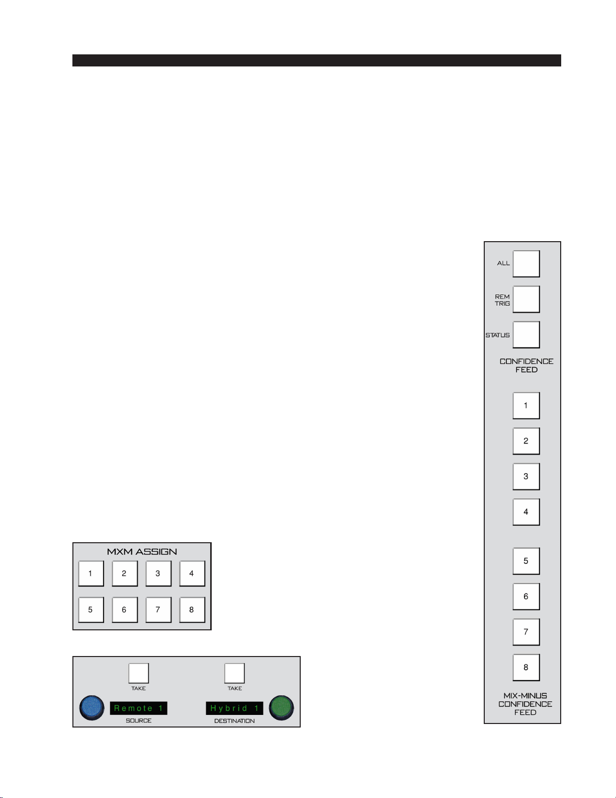
Confidence Feed Section
This system provides a means of sending an external signal to any or
all of the 8 MXM outputs. This is typically used during show setup or
airtime operations so talent can remain confident that their MXM feeds are
active and working. (A typical confidence feed signal might be master
control audio.)
A bank of 8 buttons allows user to individually route confidence audio
to a MXM output. Each feed can be unique. Additionally, all 8 outputs can
be put into confidence mode by means of a CONFIDENCE FEED ALL
switch. Also, the CONFIDENCE FEED ALL feed function can be
triggered from an external contact closure and armed for such action by
means of the REM TRIG button. To trigger the ALL function the user
defines an LIO Only input signal in the XPoint destination column with the
CONFIDENCE FEED ALL LED function. This input is cross connected
to an auto-generated mixer signal with the CONFIDENCE FEED LED
(CFLED1, for example) function attached (the signal name will be DxCF1
for confidence feeds 1 - 6 or DxCF2 for confidence feeds 7 - 12, where the
“x” represents a surface number in multi-surface systems). The remote
closure is wired to the defined logic I/O port. This allows remote control
of CONFIDENCE FEED ALL by master control switcher as the console
goes to and from air and breaks. As a result, reporters can hear the off-air
programming when dialing in and when station is in a break
All Confidence Feed programming is included in the EVENT storage.
To set and store a confidence feed signal, go to the MIX-MINUS
ASSIGN section of the MXM-D12 panel and hit the corresponding button
to establish a programming mode. Select the desired source in the XY
Controller section of the XYE-D12 panel by
rotating the SOURCE knob until the desired
signal is shown in the SOURCE display, at
which time the TAKE button will flash. Pressing that TAKE button will now program the
corresponding MXM to receive the selected
source. Repeat the procedure for each of the 8
MXM-D12 Panel
MXM outputs in the MIX-MINUS ASSIGN
section on the MXM-D12
panel.
To remove the source for
an MXM, TAKE the source
named “NOSOURCE”.
D-12 / July 2006
XYE-D12 Panel
page 34

following section for details)
MONITOR PANEL
The STATUS button, when pressed, lights, and
a list of MXM sources and destinations appears on
one of the LCD displays. After viewing the MXM
status, press the desired MONITOR button (MSTRD12 panel) to revert the display to normal operation
and turn off the STATUS light.
Monitors
There are five monitor outputs available: STUDIO 1 through 3, and
CONTROL ROOM 1 and 2.
Each monitor has a LEVEL control, a SET button,
an ON switch, and a display.
The CONTROL ROOM 1 monitor section also has
the two speaker select switches.
Pressing a monitor SET button gains access to the
monitor source encoder and master mix hot buttons.
Displays below each monitor pot show the selected
source.
MONITOR SOURCE display – shows the currently programmed source. Use rotary encoder and
TAKE to select a new source.
Monitor sources can be selected several ways:
• Four PRE-PROGRAMMED MONITOR MIXES
switches (5.1, ST1, ST2 and ST3) allow direct access to
the main mixes most frequently monitored.
• Sources can be randomly selected with the SELECT knob and its attendant SOURCE display and
TAKE button.
• The EXT switch selects the pre-programmed EXT
source. To program this, press and hold the EXT button
until it lights (approx. 3 seconds), then dial up the
desired source with the SELECT knob and press TAKE.
The source is stored. NOTE that to do this, all monitor
SET buttons must be OFF (unlit).
To select a source for a monitor by one of the above methods, first press
the SET button next to the knob for the desired monitor.
The knob controls the level of the monitor signal.
MSTR-D12 Panel
D-12 / July 2006
page 35

MONITOR PANEL
Control Room Section
In a typical radio or television application the control surface is located in
the audio control room. Speakers in the control room allow the control surface
operator to listen to the various control surface bus outputs to be assured that
the control surface is performing as desired. These speakers are fed by a stereo
or 5.1 signal routed from the control surface’s control room output.
In some instances the control surface operator may also be performing
talent whose voice will be heard over the radio. The operator’s microphone may
thus provide a part of the signal that is going out over the air. If that signal is
the one being monitored with the control room speakers, there is the potential
for feedback. The amplified signal from the control room speakers is picked up
by the microphone and reamplified to a new, higher,
level, which then is once again picked up by the
microphone. The signal quickly rises to an ear-splitting
screech. To prevent this, the operator’s microphone is
normally set in the configuration software to MUTE
the control room output to prevent the occurrence of
feedback.
CR SET BUTTON - lets the operator select the
source to be listened to in the control room speakers
using the XY Controller on the XYE-D12 panel. Source/
Destination visibility is set in XPoint.
CR DISPLAY - the eight character display shows
the source, that is selected for monitoring in the control
room.
CR LEVEL CONTROL - determines the overall
loudness of the signal being monitored as it appears in
the control room speakers.
ON SWITCH - turns the control room signal ON
and OFF. The switch LED lights to indicate the signal
is ON.
SPKR A, SPKR B - these two switches are used to
determine which of two outputs will be fed by the CR
signal. Each feed may have its mode programmed
separately (see Selecting Output Mix Destinations on
page 6-9). A/B state is stored with an EVENT.
A/B Switch Destination Mapping (Set once)
1 - Press CR SET switch
2 - Press CR SPKR A switch
3 - Use XY controller on the XYE-D12 panel to route CR to an output.
4 - Use the XYE-D12 TAKE button to store the destination.
5 - Press CR SPKR B switch
6 - Use XY controller on the XYE-D12 panel to route CR to an output.
7 - Use the XYE-D12 TAKE button to store the destination.
D-12 / July 2006
page 36

MONITOR PANEL
Studio Section
In addition to the control room, there may be one or
more studios (the D-12 supports three studios) in which
one or more performers will be assembled, usually with
microphones so that their voices can become part of the
mix. Speakers may be provided in the studio to allow the
talent to listen to the various control surface bus outputs
at times that they are not actually on air. These speakers
are fed from one of the control surface’s stereo studio
outputs.
As in the control room, the potential for feedback
also exists in the studio. The talent microphones will
usually provide a part of the signal that is going out over
the air. If that signal is the one being monitored with the
studio speakers, feedback will occur. To prevent this,
the studio mic faders are usually set to MUTE the studio
output in the configuration software to prevent the
occurrence of feedback.
ST SET BUTTON - lets the operator select the
source to be listened to in the studio using the XY
Controller on the XYE-D12 panel. Source/Destination
visibility is set in XPoint.
ST DISPLAY - the eight character display shows the
source, that is selected for monitoring in the studio.
ST LEVEL CONTROL - determines the overall
loudness of the signal being monitored as it appears in
the studio speakers.
ON SWITCH - turns the studio monitor signal ON and OFF. The
switch LED lights to indicate the signal is ON.
D-12 / July 2006
page 37

TB / MIC PANEL
TB / MIC Panel (TBM-D12)
Controls and Functions
The D-12 digital audio control surface is equipped with one
TALKBACK/MIC Panel. This panel houses the TALKBACK MIC,
the TALKBACK preselects, and the PROGRAMMABLE buttons
sections.
Programmable Buttons
These (16) momentary switches and indicating
LEDs are designed for user accessible external
functions (GPIs). Users modify behavior of the
switches/leds in the OPTIONS.TXT file for the
surface (see sample in Appendix 2). The XPoint
GUI is used to map Salvo or Preset takes or Temporary Connections to these switches.
These switches may also be mapped to control
physical Logic card output ports, and the LEDs on
the Spare buttons may also be lit by a remote device
connected to a Logic card input port. See the Bridge
Router manual for details.
T alkback Mic
The operator’s talkback mic plugs into the panel
mounted XLR connector located on the upper-right
corner of the panel. This a jack only with no preamplifier built into the D-12 control surface. This
signal is then available for the various TALKBACK
functions of the control surface. The XLR-M connector is wired to the “TB MIC” DB-9 connector
located on the control surface’s rear panel. This
DB-9 connector must be wired out to a destination,
such as a Bridge Router mic input (phantom power
is supported), to be usable by the system.
Pin 1 XLR SH – Pin 4 “TB MIC” DB-9 SH
Pin 2 XLR HI – Pin 5 “TB MIC” DB-9 HI
Pin 3 XLR LO – Pin 9 “TB MIC” DB-9 LO
XPoint software is used to route the user defined
TB MIC source signal to the D-12’s auto generated
TBACK input signal. Note that any source on the router can be the TB
source.
D-12 / July 2006
page 38

TB / MIC PANEL
Other external microphones may also be connected to the engine
system and talk to destinations or mixes and be triggered through the
system’s logic LIO-2001 I/O card (Bridge Router). This function
would be mapped through the GUI.
The TB LEVEL rotary knob is used to trim the level of the TB
signal.
T alkback Preselects
These sixteen programmable switches allow
for a dedicated Bridge Router output to be designated as a destination for the talkback signal. Once
a specific output has been programmed into the
preselector, the talkback signal can be sent to that
output at any time by pressing the corresponding
switch.
Each individual TB button is programmed as
follows:
1 - Press and hold the TAKE button (this button
will light) to enter programming mode.
2 - Press the TB button you want to program
(the TB button will flash).
3 - Rotate the SELECT rotary encoder until the
desired mix is displayed.
4 - Press the TAKE button to write the mix name
into TB switch display.
Repeat this procedure for each of the sixteen TB
buttons. The procedure will time out after about 5 seconds if you fail
to complete one of the steps.
When EVENTS are stored, the sixteen TB preselects as displayed
at the time of the EVENT SAVE action will be also stored and can be
recalled with that EVENT.
Available mixes are AUX, MXM, Studios, Masters, IFB’s, AFL,
PFL, and Sub-Groups. A TB visibility setting in the XPoint GUI allows
the user to limit what users “see” when they rotate the SELECT knob.
D-12 / July 2006
page 39

SUB-GROUPS PANEL
Sub-Groups Panel (GRP-D12)
Controls and Functions
The D-12 digital audio control surface is equipped with one SUB-GROUPS
Panel. This panel houses eight sub-group outputs.
Each sub-group has identical set of controls: SET,
ON, and AFL buttons, and MSTR and DCA assign
displays.
Output Destinations, Sub-Group 1
Example
Press a groups’s SET switch to access centralized
controls associated with the group. Central controls
include PAN/BAL, MODE, EQ, Dynamics, Test
Tone assign, and Routing. The group may be in
Surround Mode (if configured as a surround group),
Stereo, LEFT, RIGHT, or MONO modes. The group
MODE settings affects the group output but does not
affect the group signal as assigned to masters.
The DESTINATION display (XYE-D12 panel)
will show the most recent
output destination assigned.
It should be noted, however,
that a mix channel can go to
multiple destinations, and for
this reason the entire list of
XYE-D12 Panel
LCD display when that channel’s SET button is
active. If the mix is not assigned anywhere the
display will show “NoDest”.
destinations that channel is
assigned to is displayed in the
D-12 / June 2006
page 40

SUB-GROUPS PANEL
As you rotate the DESTINATION knob in the XYE-D12 panel the
names of allowable destinations will appear in the DESTINATION
display. If G1 is not currently routed to the displayed output, the TAKE
button will be lit. Press the TAKE button when lit to add the currently
displayed output as a G1 destination.
Destinations for the remaining sub-group outputs are handled in a like
manner.
Groups Output Display
Each group can be assigned to any of the
four main output buses using the MASTER
ASSIGN buttons in the MXM-D12 panel.
The assigned setting is displayed by the four
indicators of the MSTR display group.
Groups can also be assigned to MXM
masters, but this assignment is not indicated
on the GRP-D12 panel, but only on the
MXM-D12 panel.
DCA Group Displays
Each sub-group channel can be assigned
to any combination of the four DCA masters
using the DCA ASSIGN buttons in the
MXM-D12 panel. The assigned setting is
displayed by the four indicators of the DCA
MXM-D12 Panel
display group.
ON Switch
The ON switch turns the group channel signal ON, pressing it again
turns the group channel signal OFF. The switch LED lights when the group
is ON.
AFL(Solo)
This switch activates After Fader Listen (SOLO) and puts the post
fader group audio into the AFL monitor section and meter.
Sub-Groups Faders
These linear controls set the output levels of the sub-groups channels.
Nominal unity gain setting is at the -12dB point on the fader scale.
D-12 / June 2006
page 41

MASTER PANEL
Master Panel (MSTR-D12)
Controls and Functions
The D-12 digital audio control surface is equipped
with one MASTER panel. This panel houses four
MASTER program outputs, four DCA outputs,
CHANNEL PAGING buttons, the master PFL-AFL
CLEAR button, and four MONITOR mode buttons.
Masters Section
Each master mix, 5.1, S1, S2, and S3, has SET,
ON, DYN, and EQ assign switches, and a DCA
assign display.
NOTE: There are four different mix destinations: Surround (5.1), Stereo 1 (S1), Stereo 2 (S2) and Stereo 3 (S3).
For descriptive purposes we will be discussing the controls
for one section only, 5.1 Surround, with occasional references to other sections. Control descriptions for one section
also apply to identical controls at the other three destinations on the MSTR-D12 panel.
Mix Destination 5.1 Surround
Input channels are assigned to the 5.1 Surround
master by means of BUS ASSIGN button “5.1”
(MASTER ASSIGN section on the MXM-D12 panel).
Mono input sources
would pan between the
left front and right front.
Stereo inputs would
route to left front/right
front.
Mono and stereo inputs may be processed
into 5.1 Surround signals
MXM-D12 Panel
by means of the 5.1 SURROUND section on the SUR-D12 panel. 5.1
input sources would preferably route to the SURROUND output unmodified. Groups may also be routed to the masters (including the 5.1).
Master Mix Destinations
Press a master’s SET switch to access centralized controls associated
with the master. Central controls include MODE, EQ, Dynamics, Test Tone
assign, and Routing. The 5.1 master may be in Surround mode only. Stereo
masters S1, S2, and S3 may be in STEREO, LEFT, RIGHT, or MONO
modes.
D-12 / July 2006
page 42

MASTER PANEL
The DESTINATION display (XYE-D12
panel) will show the most recent output destina-
tion assigned. It should be
noted, however, that a mix
channel can go to multiple destinations, and for
this reason the entire list
of destinations that channel is assigned to is dis-
XYE-D12 Panel
played in the LCD dis-
play when that channel’s
SET button is active. If the mix is not assigned
anywhere the display will show “NoDest”.
As you rotate the DESTINATION knob in the
XYE-D12 panel the names of allowable destinations will appear in
the DESTINATION display. If 5.1 is not currently routed to the
displayed output, the TAKE button will be lit.
Destinations for the remaining master outputs are handled in a
like manner.
DYN
This switch inserts dynamic functions that have been preset by
the operator in the DYNAMICS section
in the EQD-D12 panel. The LED is lit
when dynamics are engaged.
The DYNAMICS LCD screen shows
the knob settings along with a graphical
representation of the applied dynamics.
EQD-D12 Panel
D-12 / July 2006
Settings
page 43

MASTER PANEL
This switch inserts EQ functions that have been preset by the
operator in the PARAMETRIC EQ
section of the EQD-D12 panel. The
LED is lit when EQ is engaged. When
any knob of the EQ section is rotated,
the LCD displays a graphical representation of the EQ settings, as well
as the actual knob settings.
EQD-D12 Panel
Channel Master ON/OFF
The ON switch turns the channel signal ON; pressing it again
turns the channel signal OFF. The switch LED lights to indicate
the channel is ON.
DCA Master Displays
Each channel can be assigned to any combination of the four
DCA masters using the DCA ASSIGN buttons in the MXM-D12
panel. The assigned setting is displayed by the four indicators of
the DCA display group.
Master Faders
These linear controls set the levels of the master channels.
Nominal unity gain setting is at the -12dB point on the fader scale.
NOTE that 5.1 MASTERS fader’s knob engraved with “5.1”.
D-12 / July 2006
page 44

MASTER PANEL
DCA Master Section
The DCA (Digitally Controlled Amplifier) faders allow the
user to control a cluster of Input, Subgroup, and Master faders from a single
DCA fader and ON switch. Faders
assigned to a DCA will track the
position of the DCA master. If an
input or output is “muted” by a DCA
master then the corresponding DCA
assign LED (A, B, C, or D) flashes to
indicate the DCA has control.
To assign a DCA to an input, sub-
MXM-D12 Panel
MODE and press any combination of the DCA ASSIGN buttons
on the MXM-D12 panel. The appropriate DCA display cluster on
the input, sub-group, or master panel, will be illuminated, as well
as the assign buttons.
group or master, place the input, subgroup or master channel in the SET
DCA ON
The ON switch turns the DCA master ON; faders assigned to
the master will also be turned ON.
FADER
A long-throw fader controls the relative fader level of all
inputs, groups, and masters assigned to DCA. The fader range is
0dB (no attenuation) at the top to full attenuation (OFF) at the
bottom. When a DCA master is full OFF the ON LEDs remain lit on the
cluster.
Clear PFL/AFL
When any PFL (Cue) or AFL (Solo) button on the control surface
is pressed, its light will be illuminated and flash slowly. The PFL/AFL
CLEAR button will also flash synchronously with any active PFL/AFL
buttons. Any signal can be released from cue/solo by pressing its
individual PFL/AFL button a second time. All PFL/AFL activated
buttons can be cleared at once by pressing the PFL/AFL CLEAR
button.
D-12 / July 2006
page 45

MASTER PANEL
Channel Paging Section
This section provides global page controls for the
surfaces two “pages”. Each page includes all input channel
strip knob, switch, and fader settings. D-12 control surfaces may be configured with optional PAGE switches
fitted above the input faders. A control surface with 24
physical faders will be able to control 48 input channels
strips (i.e., PAGE A controls channels 1 - 24; PAGE B controls channels
25 - 48). Each PAGE is always active, meaning input audio from a channel
may be ON and playing out a master even while its fader is switched to the
opposite page.
The PAGE A forces all input channel strips to display the top page knob,
switch, and fader settings.
The PAGE B forces all input channel strips to display the second page
knob, switch, and fader settings.
The FLIP ALL button flips the currently selected PAGE to the opposite
PAGE on all input faders (i.e., A becomes B, B becomes A). Useful for
instant LIVE to BREAK setups.
Display Monitor Controls
These switches change what information is displayed on the CHAN SET INFO LCD monitor.
There are four MONITOR buttons on the MSTRD12 panel. These buttons access various VGA display
modes. To revert to normal panel display, press the left
HOME button.
HOME - Default selection; displays the “normal” pertinent channel
information as determined by which SET button is pressed.
INFO - displays technical information about the surface’s software
versions and connection status to its companion rack MT link, Ethernet
link, and automation interface.
HELP - displays the TOP level of the built in user help system. The user
navigates the help system using the TB LEVEL knob (on the TBM-D12
panel). Hyper links to help topics are selected by “dobbying” the TB
LEVEL knob; rotating the knob advances the cursor through the available
hyperlinks. When the user exits HELP (by pressing HOME or INFO) the
cursor resets to the TOP help level.
FUNCTION - this button is reserved for future use.
D-12 / July 2006
page 46

MASTER PANEL
RESERVED FOR
FUTURE USE
D-12 / July 2006
page 47
 Loading...