

Page 1
Catalog Numbers:
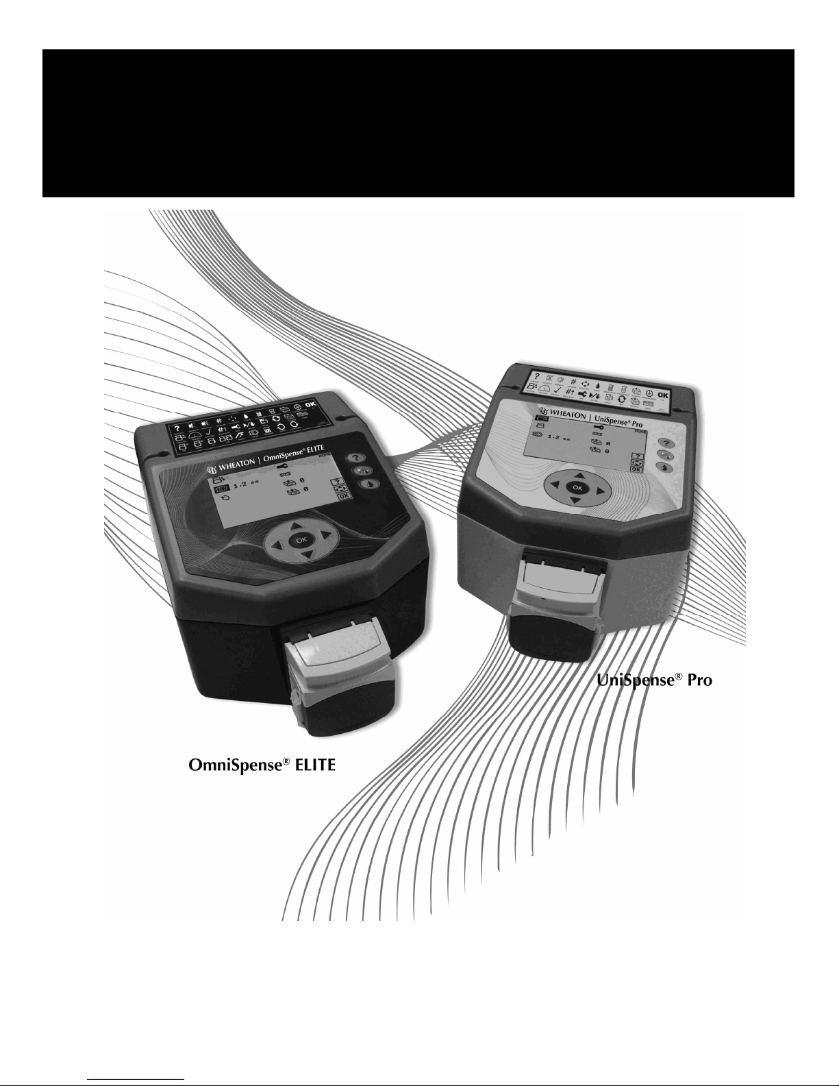
WHEATON | UniSpense®PRO
Peristaltic Pump
Instruction Manual
Instruction Manual
Instruction ManualInstruction Manual
WHEATON 800.225.1437 (U.S. & Canada Only) | 856.825.1100 | www.wheatonsci.com| P/N 50099073 Rev. 2/2/10 Lit. No.8734
W375040-A and W375040-B (100-120V)
and W375040-C through W375040-J (220-240V)
Page 2

Table of Contents
1.0 Warranty
2.0 Safety Symbols and General Safety
3.0 Specifications
4.0 Introduction
4.1 The Peristaltic Pump Process
4.2 Typical Applications
4.3 Initial Inspection
5.0 Unit Features and Component Identification
5.1 Control
5.2 User Interface
5.3 Performance Highlights
6.0 Installation
6.1 Initial Power Requirements
6.2 Power Cord Set
7.0 Initial Startup and Operation
7.1 Pump Head Attachment and Tubing Installation
7.2 Tubing Characteristics
7.3 Switching the Unit ON
7.4 Keypad Functions and Icons
7.5 Footswitch Operation and Connector Functions
7.6 Flexible Tubing Holder
8.0 Unit Setup
8.1 Language Selection
8.2 Buzzer Function
8.3 Unit Reset
9.0 Preparing for Batch and Single Dose Dispensing
10.0 Making a Calibration
10.1 Setting Operating Speed
10.2 Priming the Tubing
10.3 Calibration Dispense
11.0 Making Batch and Single Dose Dispenses
11.1 Batch Count
11.2 Volume per Dispense
11.3 Delay Between Dispenses
11.4 Making a Dispense
11.5 To Adjust the Volume During a Batch Dispense
11.6 To Run Additional Batches with the Same Settings
12.0 Memory Storage and Recall
12.1 To Store a Parameter
12.2 To Recall a Parameter
13.0 Tips for Obtaining Maximum Accuracy
14.0 Maintenance and Troubleshooting
14.1 Maintenance
14.2 Troubleshooting – For Qualified Maintenance Personnel Only
14.3 Fuse Replacement
15.0 Illustrations and Diagrams
16.0 Declarations of Conformity and WEEE Statement
2
WHEATON UniSpense® PRO Peristaltic Pump
WHEATON | 800.225.1437 (U.S. & Canada Only) | 856.825.1100 | www.wheatonsci.com| P/N 50099073 Rev. 2/2/10 Lit. No.8734
Page 3

UniSpense® PRO Parts Lists and Illustrations
FIG A Major Component Identification
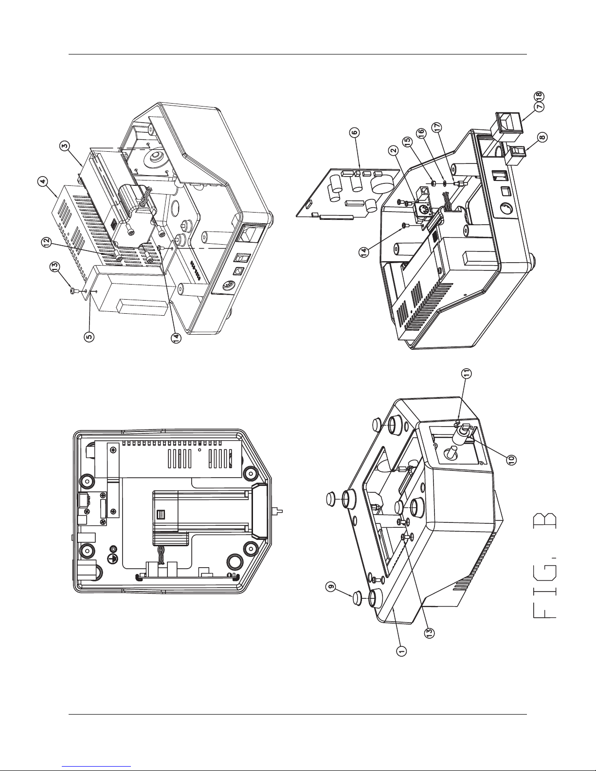
FIG B Lower Housing Assembly
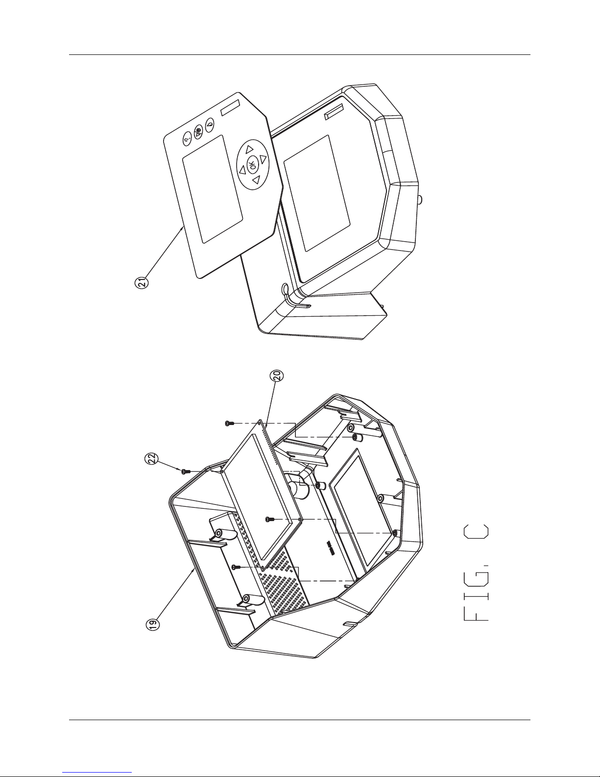
FIG C Upper Housing Assembly
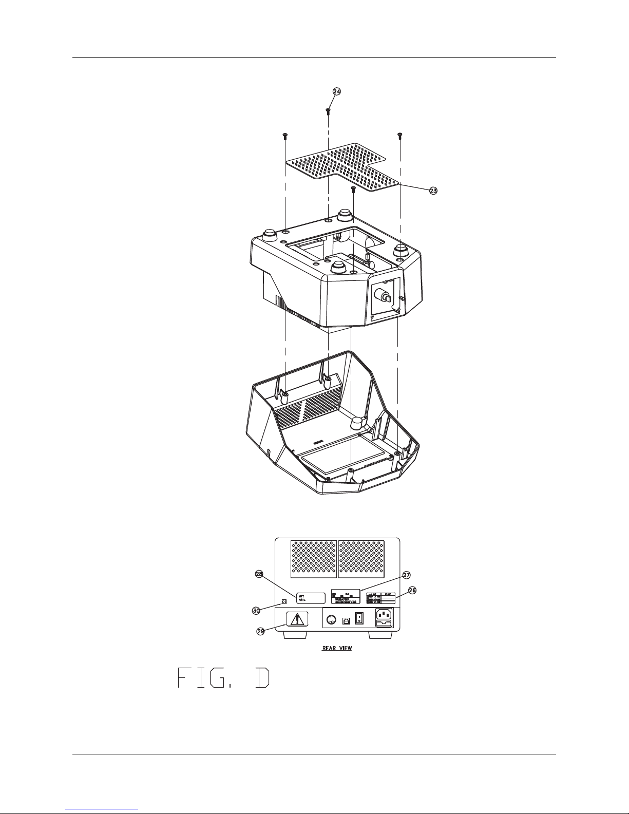
FIG D Complete Assembly
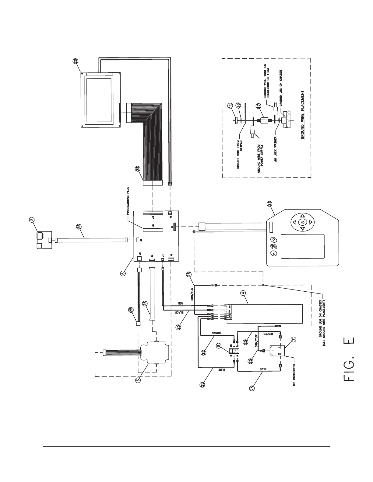
FIG E Wiring Diagram
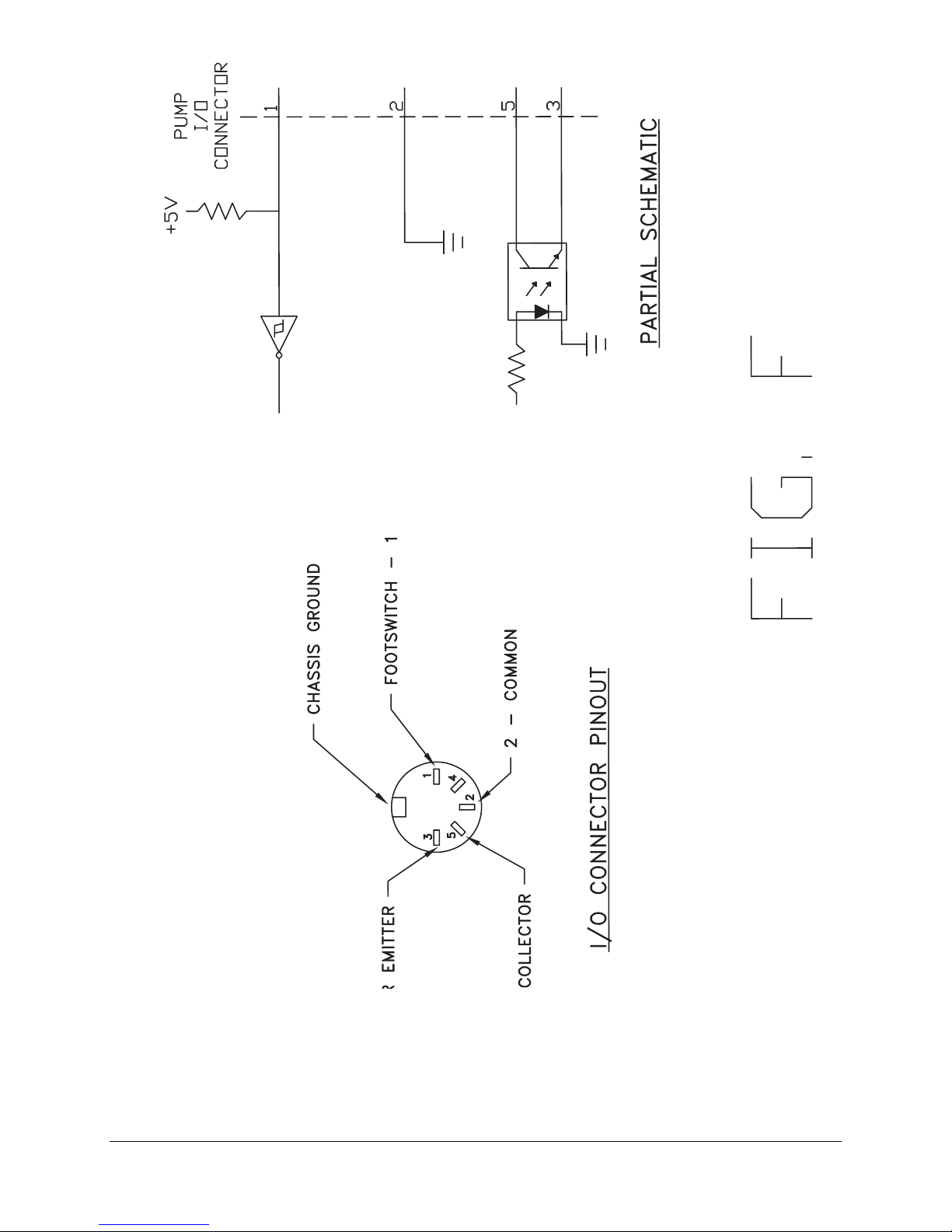
FIG F Remote Footswitch Connector and Pin Outs
WHEATON UniSpense® PRO Peristaltic Pump
1.0 Limited Warranty
All goods and materials shall conform to WHEATON Industries Inc. specifications at the time of
shipment from our plant. WHEATON Industries warrants this product to be free from defects in material
and workmanship for a period of 365 days from the date of shipment. If the repair or adjustment is
necessary within the warranty period and has not been the result of mishandling or abuse, WHEATON
will either correct the non-conforming condition, or replace any nonconforming goods or materials or
issue a credit in the amount of the purchase price paid and received for such goods. All claims for
product nonconformity must be made within ten (10) days of identifying such a problem by calling
Customer Service at 800.225.1437 (U.S., Puerto Rico and Canada); or Internationally at 856.825.1100
and then providing the Model, Serial and Catalog Number of the product. Items returned are to be
packed very carefully so as to prevent damage in transit. WHEATON will also repair or adjust any
product that is beyond the warranty period for a nominal fee.
WHEATON makes no other express or implied warranty, statutory or otherwise, concerning
materials or goods supplied, including without limitation, ANY WARRANTY of fitness for a
particular purpose or any warranty of merchantability. The warranties given are exclusive of all
other warranties expressed or implied. WHEATON shall not be liable for consequential, special or
incidental damages.
To expedite any technical or service request, please have the following information available.
Thank you.
Model:
Serial #:
Catalog #:
2.0 Safety Symbols Used in this Manual and On This Product
A WARNING symbol indicates attention to an operation which can cause operator injury,
improper function of or damage to the equipment and possible problems with the process.
An ELECTRICAL DANGER symbol indicates attention to an operation which could cause
electrocution or severe injury.
WHEATON | 800.225.1437 (U.S. & Canada Only) | 856.825.1100 | www.wheatonsci.com| P/N 50099073 Rev. 2/2/10 Lit. No.8734
3
Page 4

WHEATON UniSpense® PRO Peristaltic Pump
General Safety Rules
WARNING. READ AND UNDERSTAND ALL INSTRUCTIONS. Failure to follow all
instructions listed below may result in electrical shock, fire and / or serious personal injury.
SAVE THESE INSTRUCTIONS
1. Know your instrument - Read the operating manual carefully. Learn the equipment's application and
limitations.
2. Ground all equipment - If electrical, this instrument is equipped with a grounding type plug. The
green/yellow conductor in the cord is the grounding wire and should never be connected to a live
terminal.
3. Avoid dangerous environment - Electrical instruments designed to process liquids must be operated
with extreme caution. If liquid comes in contact with internal electrical components or wires, fire or
electrical shock may occur. Adequate surrounding work space should be provided during use. Do not
operate electrical instrumentation in a combustible atmosphere.
4. Work surface - Keep well lighted. Be certain the work surface is clean, level and sturdy enough to
support the weight of the unit, particularly if it is to be filled with liquid.
5. Wear proper apparel - Do not wear loose clothing, neckties or jewelry that might get caught in moving
parts. Non-slip footwear is recommended. Wear protective hair covering to contain long hair.
6. Wear safety goggles - Wear safety goggles at all times. Everyday eyeglasses only have impact
resistant lenses, they are NOT safety glasses.
7. Don’t Overreach - Keep proper footing and balance at all times.
8. Maintain instrument with care - Keep screws tight and unit clean. Check periodically for worn or
damaged parts. Inspect the plug and cord before each use. Do not operate this instrument if there are
signs of damage.
9. Avoid accidental start up - If electrical, always make sure the switch is in the "OFF" position before
plugging instrument into outlet.
10. Disconnect Instrument - Always disconnect the instrument from the power source before servicing.
11. Do not block cooling vents if provided.
12. Do not operate this equipment in any manner not specified in this manual.
13. It is recommended that a fire extinguisher always be located in areas where electrical
instruments are being used.
Specific Safety Considerations
WARNING ! IMPROPER GROUNDING CAN RESULT IN ELECTRICAL SHOCK. IN THE
EVENT OF A SHORT CIRCUIT, GROUNDING REDUCES THE RISK OF SHOCK. THIS
INSTRUMENT MUST BE GROUNDED.
This instrument is equipped with a cord having a grounding wire and an appropriate grounding plug. The
plug must be used with an outlet that has been installed and grounded in accordance with all local codes
and ordinances. The outlet must have the same configuration as the plug. DO NOT USE AN ADAPTER.
Do not modify the line cord that has been provided. If it does not fit the available outlet, contact your
nearest WHEATON Industries distributor for the proper line cord for your geographic area.
WHEATON | 800.225.1437 (U.S. & Canada Only) | 856.825.1100 | www.wheatonsci.com| P/N 50099073 Rev. 2/2/10 Lit. No.8734
4
Page 5

WHEATON UniSpense® PRO Peristaltic Pump
3.0 Specifications – UniSpense® PRO
Operating Voltage: Nominal 100-240 VAC 50/60 Hz
Power Consumption: 37 watts maximum
Fuses: 2.0 AT 5X20MM 250V – (100-120V)
1.0 AT 5X20MM 250V – (220-240V)
Fixed Operating Speeds: 75 and 150 RPM (selectable)
Installation Category: Class II
Environmental: Operating temperature: 15°C to 40°C
Humidity: 80% up to 31°C / 50% at 40°C
Altitude limit: 2000 meters
Overall Dimensions: 7” H x 8 ¾” W x 13” D (in)
(includes attached pump head) 17.8H x 22.3W x 33.0D (cm)
Weight: 11.8 lbs, 5.4 kg
Available WHEATON Tubing Sizes: 2,3,6,8 mm ID
Maximum Dispense Range for
All Tubing Sizes: .01 - 9999.99 mL
Approximate Flow Rate Ranges
For Various Tubing Sizes, +/- 3%: 2.0mm ID: 0.5 mL/sec and 1.0 mL/sec
3.0mm ID: 1.0 mL/sec and 2.0 mL/sec
6.0mm ID: 3.5 mL/sec and 7.1 mL/sec
8.0mm ID: 5.6 mL/sec and 11.2 mL/sec
Vertical Head Height: APPROXIMATELY 6 FT (2 METERS)
Ingress Protection Rating: 31
4.0 Introduction
The UniSpense® PRO is the latest generation liquid dispenser from WHEATON Industries, Inc., which
features precision microprocessor control of a wide range of dispensing parameters.
4.1 The Peristaltic Pump Process
Fluid is contained within a flexible tube, which is placed in the precision pump head. The center rotor, with
a number of rollers, compresses the flexible tube. As the rotor turns, the part of tube under compression
closes and forces the fluid to be pumped to move through the tube. After the roller passes, the tube
opens to its natural state and fluid flow is induced to the tubing. This process is called peristalsis. The
pump has no contact with the fluid being transferred.
WHEATON | 800.225.1437 (U.S. & Canada Only) | 856.825.1100 | www.wheatonsci.com| P/N 50099073 Rev. 2/2/10 Lit. No.8734
5
Page 6

WHEATON UniSpense® PRO Peristaltic Pump
4.2 Typical Applications
Peristaltic pumps can be used with a large variety of liquids. Particularly corrosive, abrasive and
suspension liquids are all good candidates for peristaltic pump applications.
Peristaltic pumps require little maintenance, are easy to install, have few moving parts, and are easy to
use.
4.3 Initial Inspection
When you receive your new UniSpense® PRO, inspect it for any obvious damage that may have
occurred during shipment. If any damage is found, notify the carrier at once. Warranty information is
provided at the front of this manual. Check to confirm that there are no broken switches, displays or pump
heads, and that the unit is not dented or scratched. Retain packaging until all parts and unit functionality
are confirmed.
Components Supplied
• UniSpense® PRO peristaltic pump
• Pump Head
• Line Cord – supplied to fit your local electrical outlet specifications
• Flexible Tubing Holder
• Operators manual
• Quick Start Card
• Icon Help Sticker
5.0 Unit Features and Components Identification
Refer to Figure A for component identification
Power inlet module: Location of the line cord entry and fuse(s) compartment.
Keypad: Allows all setting and operation parameters to be entered.
Screen: A unique icon-driven display allows easy viewing of unit functions and parameters.
I/O Interface Connection5: Connection for an optional footswitch. Also contains feedback outputs for
remote control. Connector pin details are located in Figure F.
Pump Head: Other optional pump heads can be mounted on the unit, (see section 6.1). Tubing is loaded
by simply raising the cover on the pump head, and snapping closed. The tubing holders may need to be
adjusted on the side of the pump head. These are adjusted
WHEATON | 800.225.1437 (U.S. & Canada Only) | 856.825.1100 | www.wheatonsci.com| P/N 50099073 Rev. 2/2/10 Lit. No.8734
6
Page 7

WHEATON UniSpense® PRO Peristaltic Pump
5.1 Control
The UniSpense® PRO can be used in both laboratory and industrial settings. In addition to the front-panel
keypad, the pump can be triggered to run remotely either by the optional footswitch, or by a dry contact
relay or isolated open collector transistor output as part of a more advanced automated dispensing
system. The UniSpense® PRO is capable of sending an End of Dispense (EOD) feedback signal to a
controller for remote automated operation.
5.2 User Interface
A chemical resistant membrane keypad allows direct user entry of volume, tubing size, automatic delay
interval, ramp time, pump direction, pump speed, pump function and dose count. Additional user selective
functions include calibration, memory functions and audible cycle alert. The self-prompting, symbolic LCD
screen ensures quick setup and ease of operation.
5.3 Performance Highlights
An adjustable delay can be set from 0.5 to 99.9 seconds between doses to accommodate user dexterity
and work load. The pump can be activated by depressing either the front panel mounted start key, or the
optional footswitch for hands-free operation.
Up to 9 pre-selected set-ups can be stored in memory and quickly retrieved for later use. Selections
stored in memory are preserved even after powering the unit down. Pump speed is selectable at 75 and
150 RPM. A flexible tubing support stand is included to facilitate hands-free operation.
6.0 Installation
Install the unit where there will be adequate room for the unit to operate. Provide enough clearance
around the unit to keep items away from the rotating pumps and tubing.
6.1 Input Power Requirements
This equipment is designed to operate from a 100-240V single-phase AC power source at 47 to 63 Hz.
The line voltage / fuse label located on the lower rear of the unit shows the nominal input voltage set for
the unit at the factory.
6.2 Power Cord Set
This unit has been shipped from the factory with a power line cord that has a plug appropriate for your
area. If the wrong power cord has been shipped for your particular application, contact your nearest
WHEATON Industries dealer for the proper cord. The UniSpense® PRO has been equipped with a 3-wire
grounding type power cord. The unit is only grounded when it is plugged into an appropriate receptacle.
Do not operate the unit without adequate grounding protection.
7.0 Initial Startup and Operation
CAUTION: Keep hands and fingers away from rotating parts of the machine. Make sure
tubing is secured and clamped properly before running pump. Pump should be turned off
and unplugged while loading tubing into pump head.
7
WHEATON | 800.225.1437 (U.S. & Canada Only) | 856.825.1100 | www.wheatonsci.com| P/N 50099073 Rev. 2/2/10 Lit. No.8734
Page 8
7.1 Pump Head Attachment and Tubing Installation
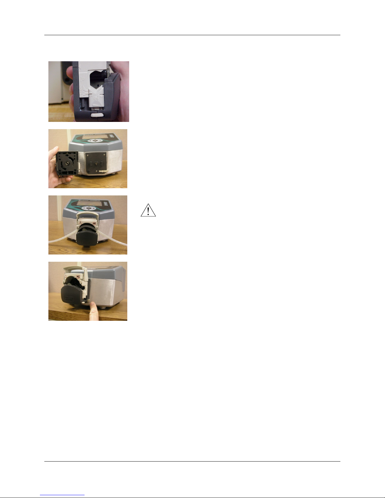
Pump Head Setup - Raise the cover on the pump head so that the
arrow (upper left) points to the mark on the pump frame. Identify the
tubing bore diameter from the tubing manufacturer’s packaging. Using
the graduations on the side of the head, adjust the tubing clamps on
both sides via the thumbscrews at the bottom of the pump head to the
proper tubing bore size.
Pump Head Attachment - Align the pump drive shaft tang with the
drive rotor slot on the back of the head. Align the slots on the back of
the head with the ears on the pump head mounting plate. Place the
pump head on the mounting plate and twist the pump head clockwise
until it clicks into place.
Tubing Installation – Insert Tubing into the pump head between the
pump head cover and the rollers. The dispensing end should be
located to the right. Close the pump head cover to secure the tubing.
Make sure tubing is not twisted and has no kinks.
WHEATON UniSpense® PRO Peristaltic Pump
CAUTION! Improper adjustment of the tubing clamps may
result in improper performance of tubing, or premature wear and
failure of tubing. DOUBLE CHECK clamp settings before
proceeding.
To Remove Pump Head – Press the release tab at the lower right of
the pump head. While holding the release tab, rotate the pump head
counterclockwise and pull off.
7.2 Tubing Characteristics
Silicone tubing exhibits a wide range of chemical resistivity and should be suitable for most general
dispensing applications. However, there are a few organic substances which cannot be dispensed
accurately due to their effects on silicone tubing. These substances include hydrocarbons, acids and
halogenated hydrocarbons. To determine if a particular tubing-chemical combination is compatible,
immerse a 100mm length of tubing in the chemical in question for 72 hours at room temperature. If after
this time period the tubing has increased or decreased in length by less than 3%, the combination is
compatible. Length changes of 3% to 8% are worth trying, but will not produce the most accurate results.
Changes in length over 8% are considered to be unsatisfactory. It should also be noted that a new tubing
assembly may cause slight filling variations for the first one to two hours of operation.
7.3 Switching the Unit ON
WHEATON | 800.225.1437 (U.S. & Canada Only) | 856.825.1100 | www.wheatonsci.com| P/N 50099073 Rev. 2/2/10 Lit. No.8734
8
Page 9
WHEATON UniSpense® PRO Peristaltic Pump
Active Key
s Available
Screen
Name
Function Icons (Highlighted)
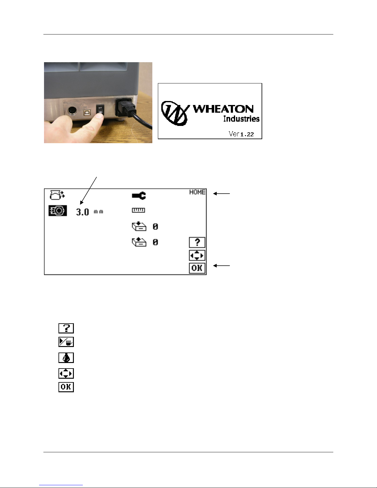
Switch the pump ON via the power switch on the rear panel. The main screen displays the WHEATON
Industries logo and the firmware version level.
The pump will automatically transition to the HOME screen. Additional screens feature a similar layout:
7.4 Keypad Functions and Icons
Icons on the right of each screen show the user which keys will be active during function and setup
navigation. A brief explanation of active keys is listed:
Help – Pushing the help button will show icon explanations in several languages
Run/Stop – Starts and stops the pump
Prime – Push and hold the button to run the pump at a fixed speed to purge air from
the tubing
Arrow Keys – Used to navigate menu items, and adjust parameters and values
OK – Confirms an entry of a parameter or value. Also returns unit to home screen.
WHEATON | 800.225.1437 (U.S. & Canada Only) | 856.825.1100 | www.wheatonsci.com| P/N 50099073 Rev. 2/2/10 Lit. No.8734
9
Page 10
WHEATON UniSpense® PRO Peristaltic Pump
7.5 Footswitch Operation and Connector Functions
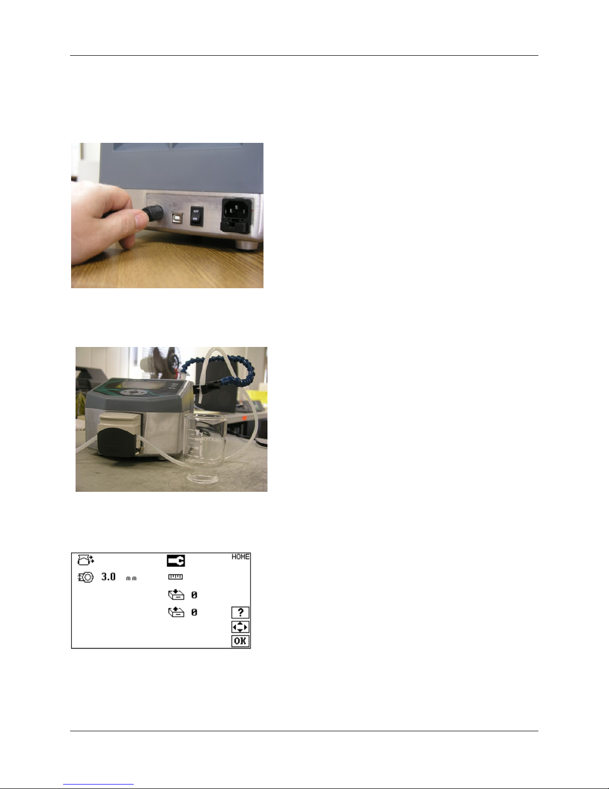
Plug the optional foot switch into the Interface Connector found at the rear of the unit. If the unit is at idle,
pressing the footswitch once, will initiate a pump dispensing sequence, as defined by the entries made by
the user via the main front panel keypad. If the unit is running, pressing the footswitch once will stop the
pump.
In addition to connections for the above footswitch, the
interface Connector contains feedback pinouts for a Pump
Running / Pump Stopped indicator.
Pins 1 (footswitch +) and 2 (footswitch GND) are +5V TTL
compatible inputs with pull up resistors, and can be driven
by an isolated open collector device or dry contact relay, to
start and stop the unit.
Pins 3 and 5 are an isolated transistor output capable of
driving a TTL load with pull up resistor. When the pump is
running, the transistor is ON, and when the pump is
stopped, the transistor is OFF.
See Figure F for connector pin out details.
7.6 Flexible Tubing Holder
An included flexible tubing holder mounts to either side of
the unit, and can be flexed to the desired position, for
hands-free operation of unit.
8.0 Unit Setup
The setup menu contains a collection of lesser used functions of the unit. From the HOME screen, use
the UP and DOWN keys to navigate to the SETUP icon, and then press OK.
WHEATON | 800.225.1437 (U.S. & Canada Only) | 856.825.1100 | www.wheatonsci.com| P/N 50099073 Rev. 2/2/10 Lit. No.8734
10
Page 11
WHEATON UniSpense® PRO Peristaltic Pump
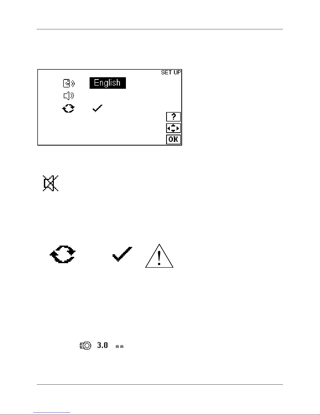
8.1 Language Selection
Press the UP and DOWN and the LEFT and RIGHT keys to access the Language Selection. Help
screens are available in the following languages: English, French, German, Spanish, Japanese, Chinese,
and Korean. Press OK when done.
8.2 Buzzer Function
Press the UP and DOWN and the LEFT and RIGHT keys to access the Buzzer Function.
Turning the buzzer function ON will cause the unit to sound an end-of-dispense alert. Turning the buzzer
function OFF (shown) will disable the buzzer during the dispense cycle.
8.3 Unit Reset
Press the UP and DOWN and the LEFT and RIGHT keys to access the Unit Reset Function.
WARNING! – Resetting the unit will return the unit to factory setup parameters. It will NOT clear any
settings stored in memory.
To reset the unit, highlight the ‘check’ mark, and press OK. A special tone will sound when the unit resets.
9.0 Preparing for Batch and Single Dose Dispensing
Press the OK button to transition to the HOME screen. Set the tubing size by pressing the UP and
DOWN keys to move to the tubing icon. Use the LEFT and RIGHT arrows to navigate the number fields,
and the UP and DOWN icons to adjust the number fields. Press the OK button when done.
WHEATON | 800.225.1437 (U.S. & Canada Only) | 856.825.1100 | www.wheatonsci.com| P/N 50099073 Rev. 2/2/10 Lit. No.8734
11
Page 12
WHEATON UniSpense® PRO Peristaltic Pump
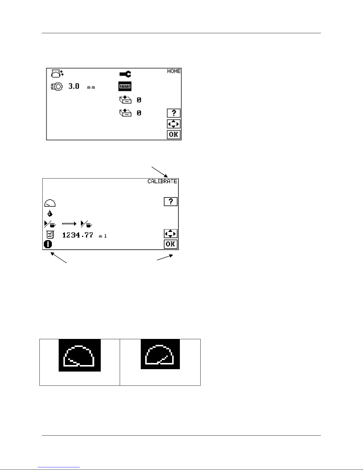
Calibrate Screen
10.0 Making a Calibration
Use the UP and DOWN arrows in the HOME screen to navigate to the calibration icon.
Press OK to navigate to the CALIBRATE screen.
Pump Running /
Stopped Icon
Active
Keys
10.1 Setting Operating Speed
Use the LEFT and RIGHT buttons to select the calibration speed. Set the Calibration Speed so that the
pump runs for at least 15 seconds during the calibration run. This may require some trial and error. The
longer the pump runs the more accurate the calibration. It is important to calibrate at the same speed you
will be using for the dispense mose.
75 RPM
150 RPM
12
WHEATON | 800.225.1437 (U.S. & Canada Only) | 856.825.1100 | www.wheatonsci.com| P/N 50099073 Rev. 2/2/10 Lit. No.8734
Page 13
WHEATON UniSpense® PRO Peristaltic Pump
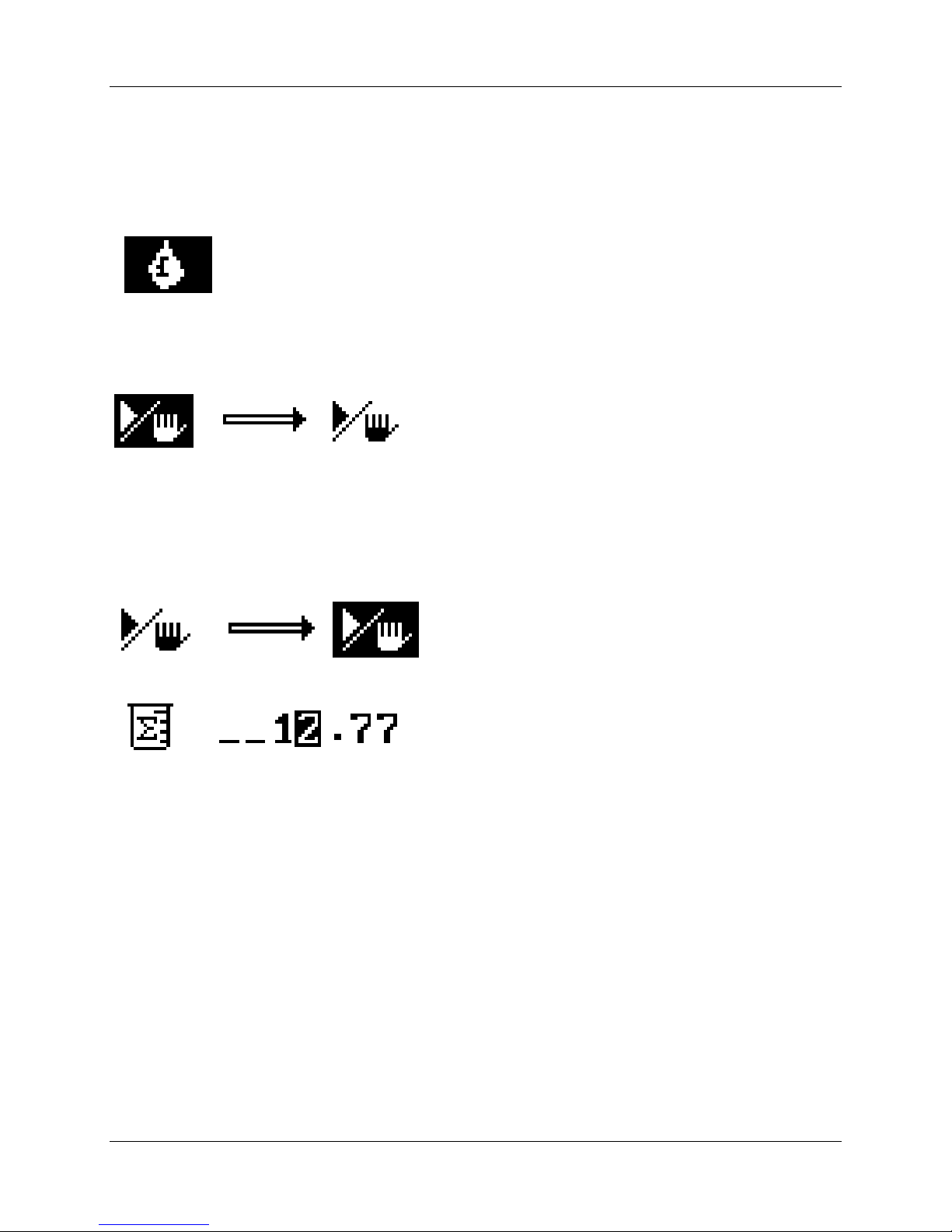
10.2 Priming the Tubing
Use the UP and DOWN buttons to select the PRIME icon. The PRIME button on the keypad now
becomes active. Push and HOLD the prime button on the keypad to run the pump motor and purge any
air from the tubing. RELEASE the prime button to stop the motor.
10.3 Calibration Dispense
Use the UP and DOWN button to navigate the Calibration Dispense icon:
Prepare to measure a dispense by using a graduated cylinder, electronic scale, or other device that can
accurately measure volume. Press the START / STOP button to begin a
best results, the pump should run for a minimum of 15 seconds. The longer the run time the more
accurate the calibration.
calibration dispense.
For
Press the START / STOP button to end the calibration dispense.
Use the UP and DOWN buttons and the LEFT and RIGHT buttons to enter the measured volume:
Press OK to enter the volume and complete the calibration procedure. Press OK again to return to the
HOME screen.
WHEATON | 800.225.1437 (U.S. & Canada Only) | 856.825.1100 | www.wheatonsci.com| P/N 50099073 Rev. 2/2/10 Lit. No.8734
13
Page 14
WHEATON UniSpense® PRO Peristaltic Pump
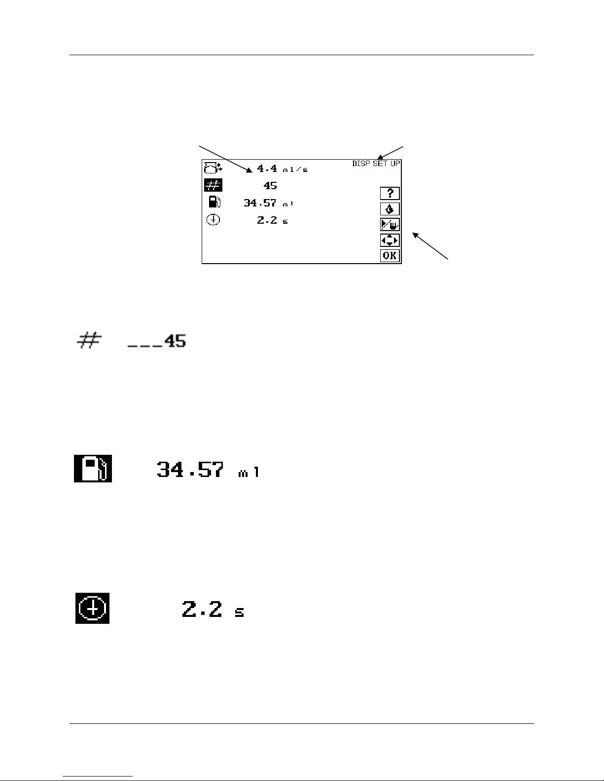
11.0 Making Batch and Single Dose Dispenses
From the HOME screen, press OK to navigate to the DISPENSE SETUP screen:
Flow rate
Mode
Active Keys
11.1 Batch Count
Use the UP and DOWN keys to navigate to the batch count. The allowable range is 1 – 99999:
Use the UP and DOWN and the LEFT and RIGHT keys to enter the batch count. Press OK when done.
Entering 1 will provide a single dispense.
11.2 Volume per Dispense
Use the UP and DOWN keys to navigate to the Volume per Dispense icon:
Use the UP and DOWN and the LEFT and RIGHT keys to enter volume per dispense. Press OK when
done.
11.3 Delay Between Dispenses
Use the UP and DOWN keys to navigate to the Delay icon. The available range is 0.5 – 9.99 seconds:
Use the UP and DOWN and the LEFT and RIGHT keys to enter the delay in seconds between dispenses.
Press OK when done.
14
WHEATON | 800.225.1437 (U.S. & Canada Only) | 856.825.1100 | www.wheatonsci.com| P/N 50099073 Rev. 2/2/10 Lit. No.8734
Page 15
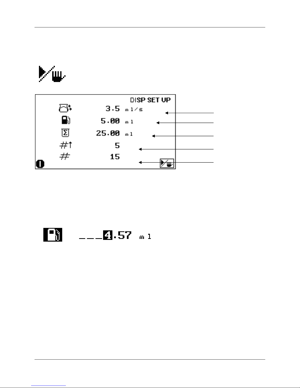
Volume
Total # of Dispenses
# of Dispenses
Flow Rate
11.4 Making a Dispense
Press the START / STOP button to start a batch dispense:
WHEATON UniSpense® PRO Peristaltic Pump
Accumulated Volume
The pump will make dispenses with the settings programmed, and stop when the total number of
dispenses are made.
11.5 To Adjust the Volume During a Batch Dispense
The dispensed volume can be adjusted during a batch dispense, by pressing the Start / Stop button, and
then using the UP and DOWN and the LEFT and RIGHT keys to enter the dispense volume. Press OK
when done. Press the Start / Stop button to resume batch dispensing.
11.6 To Run Additional Batches with the Same Settings
Press the Start / Stop button to start a fresh dispense batch.
12.0 Memory Storage and Recall - Available Registers: (1-9)
All set parameters, including set volume, delay interval, dispense count, calibration, pump speed, etc. can
be stored in non-volatile memory, and easily recalled. This is especially useful when the pump is used in
several applications, each requiring its own particular setup parameters. Stored parameters can be
quickly recalled, and the pump made ready for a particular operation.
WHEATON | 800.225.1437 (U.S. & Canada Only) | 856.825.1100 | www.wheatonsci.com| P/N 50099073 Rev. 2/2/10 Lit. No.8734
15
Page 16
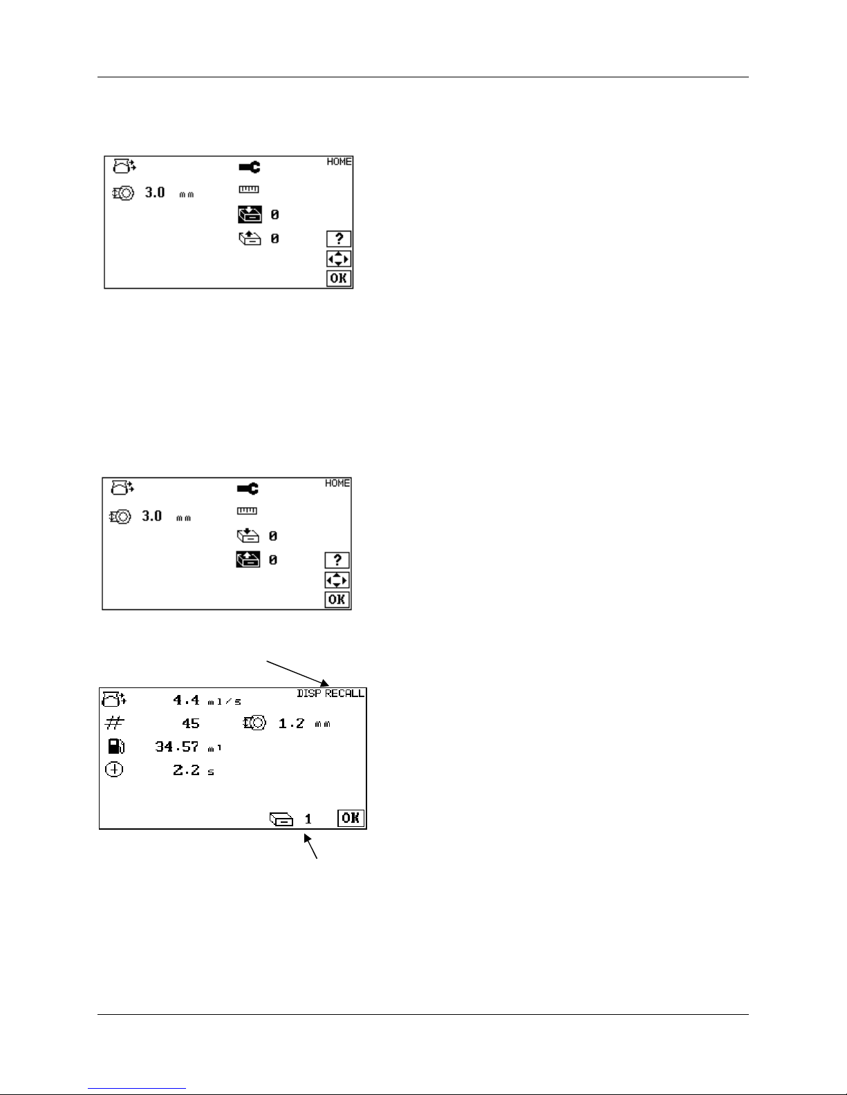
WHEATON UniSpense® PRO Peristaltic Pump
RECALL SCREEN
12.1 To Store a Parameter
Set all pump parameters to desired settings. Navigate to the HOME screen and select the storage icon:
Use the UP and DOWN and the LEFT and RIGHT to select a storage register (1-9). Press the OK key to
store parameters in non-volatile memory. A special tone will sound to confirm storage of parameters. If
parameters are stored in a register already containing data, the old data will be overwritten with the new
parameters.
12.2 To Recall a Parameter
Press the UP and DOWN and the LEFT and RIGHT keys to recall a storage register (1-9), and then press
OK. A special tone will sound to confirm recall of parameters. If the unit appears to skip over certain
registers when recalling a parameter, it means that the register skipped is empty. An empty storage
register will not be accessible.
The contents of a RECALL register can be previewed by pressing the ? (info) key and pressing OK when
done.
Previewing Memory Register #1
16
WHEATON | 800.225.1437 (U.S. & Canada Only) | 856.825.1100 | www.wheatonsci.com| P/N 50099073 Rev. 2/2/10 Lit. No.8734
Page 17

WHEATON UniSpense® PRO Peristaltic Pump
13.0 Tips on Obtaining Maximum Accuracy
Several operating variables must be considered in obtaining maximum dispense accuracy, such as tubing
sizes, and pump speed. In addition other variables such as tubing characteristics (material, age, chemical
compatibility) and pumped – medium characteristics (viscosity, chemical makeup, temperature) must also
be considered in obtaining best dispensing results.
Proper Tubing Selection
Each different tubing size will provide a different liquid delivery range when used in conjunction with the
pump unit. Accuracy is increased as the number of pump head revolutions required per dispense is
increased. Tubing size should be selected so the pump head makes at least 3 complete revolutions.
14.0 Maintenance and Troubleshooting
DANGER! NEVER ATTEMPT TO PERFORM REPAIRS IF THIS INSTRUMENT IS
PLUGGED IN! TO AVOID SERIOUS ELECTRIC SHOCK OR ELECTROCUTION, THIS
INSTRUMENT MUST BE DISCONNECTED FROM THE SOURCE OF AC POWER
BEFORE REMOVAL OF ANY PROTECTIVE COVERS.
14.1 Maintenance
Routine user maintenance should include a regular inspection of the tubing assembly for excessive wear
and leaks. Many service problems can often be cured by simply replacing a worn tubing assembly. To
insure high accuracy, the pump rotor and tubing clamping mechanics of the pump head should be kept as
clean as possible at all times.
The unit cabinetry has been designed to an IP31 rating. The plastic top is mineral filled polypropylene and
the base is painted cast aluminum. The pump head and outer cabinet may be wiped down with warm
water and any mild household cleaning solution. Never use abrasive cleaners or strong acids as cleaning
solutions. Never place liquid containers on top of the UniSpense® PRO, as a spill could result in liquid
entering the dispenser. If liquid should accidentally contact the front panel, the unit should be
disconnected from the AC power source immediately and carefully dried with towels and warm air.
Although the UniSpense® PRO is designed for easy service, it is highly recommended that the instrument
be returned to WHEATON Industries should any major repairs be needed.
Pump rollers can be occasionally lubricated with Teflon lubricating oil.
14.2 Troubleshooting – For Qualified Maintenance Personnel Only!
DANGER! NEVER ATTEMPT TO PERFORM REPAIRS IF THIS INSTRUMENT IS
PLUGGED IN ! TO AVOID SERIOUS ELECTRIC SHOCK OR ELECTROCUTION, THIS
INSTRUMENT MUST BE DISCONNECTED FROM THE SOURCE OF AC POWER
BEFORE REMOVAL OF ANY PROTECTIVE COVERS.
WHEATON | 800.225.1437 (U.S. & Canada Only) | 856.825.1100 | www.wheatonsci.com| P/N 50099073 Rev. 2/2/10 Lit. No.8734
17
Page 18

WHEATON UniSpense® PRO Peristaltic Pump
Unit will not operate:
Cause: Fuse blown.
Remedy: Replace fuse with proper size and type. (see ‘Fuse Replacement’)
Cause: Supply voltage low or at zero.
Remedy: Check house receptacle with a voltmeter.
Cause: On/Off power switch in "off" position.
Remedy: Switch power switch to "on" position.
Motor runs but pump head will not turn;
Cause: Pump head not properly engaged with drive shaft.
Remedy: Realign pump head with drive shaft (see ‘Initial Startup and Operation).
Switch on but motor fails to rotate;
Cause: Pump speed set too low.
Remedy: Increase pump motor speed as required.
Cause: Motor control board defective.
Remedy: Replace defective board.
Cause: START Key not pressed.
Remedy: See ‘Unit Features and Component Identification’ for keypad and display
operation.
Unit will not cycle automatically:
Cause: Multiple doses are not entered.
Remedy: See ‘Preparing for Batch and Single Dose Dispensing.
Cause: Dispense cycle not initiated.
Remedy: START key must be pressed to initiate the dispense cycle.
Pump head turns, but unit will not pump;
Cause: Tubing assembly incorrectly installed.
Remedy: Tubing must be installed as described in section ‘Initial Startup and Operation’.
Cause: Tubing assembly worn or split.
Remedy: Replace tubing assembly.
Motor fails to maintain constant rotation speed;
Cause: Motor control board defective.
Remedy: Have defective control board replaced.
Cause: Drive motor defective.
Remedy: Have defective motor replaced.
18
WHEATON | 800.225.1437 (U.S. & Canada Only) | 856.825.1100 | www.wheatonsci.com| P/N 50099073 Rev. 2/2/10 Lit. No.8734
Page 19

WHEATON UniSpense® PRO Peristaltic Pump
Liquid continues to drip from tubing even after pump has stopped;
Cause: Tubing is worn.
Remedy: Replace with fresh tubing.
Cause: Tubing Wall Thickness mismatch with pump head used.
Remedy: Tubing wall weight should match pump head specifications.
Inaccurate Volume Delivery
Cause: Tubing assembly worn.
Remedy: Replace tubing assembly.
Cause: Pump not calibrated properly.
Remedy: Calibrate unit as described in ‘Making a Calibration’ section.
Cause: Defective electronics.
Remedy: Refer problem to authorized repair agent.
Cause: Side clamps on pump head not adjusted properly.
Remedy: Adjust per instructions in ‘Initial Startup and Operation’.
19
WHEATON | 800.225.1437 (U.S. & Canada Only) | 856.825.1100 | www.wheatonsci.com| P/N 50099073 Rev. 2/2/10 Lit. No.8734
Page 20
WHEATON UniSpense® PRO Peristaltic Pump
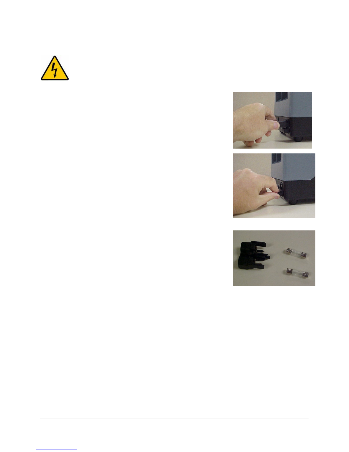
14.3 Fuse Replacement
DANGER! BE CERTAIN THE UNIT IS DISCONNECTED FROM THE AC POWER
SOURCE.
1. Disconnect the cord-set from the AC power source.
2. Remove the fuse drawer by using a small flat screwdriver to lift
the tab.
3. Replace with new fuses:
108 - 120 vac unit use (2) 5x20mm, 250V, 2.0 AT fuses, be sure the correct cord set is used.
220-240 vac unit use (2) 5x20 mm 240V 1.0 AT fuses, be sure the correct cord set is used.
15.0 Illustrations and Diagrams
20
WHEATON | 800.225.1437 (U.S. & Canada Only) | 856.825.1100 | www.wheatonsci.com| P/N 50099073 Rev. 2/2/10 Lit. No.8734
Page 21
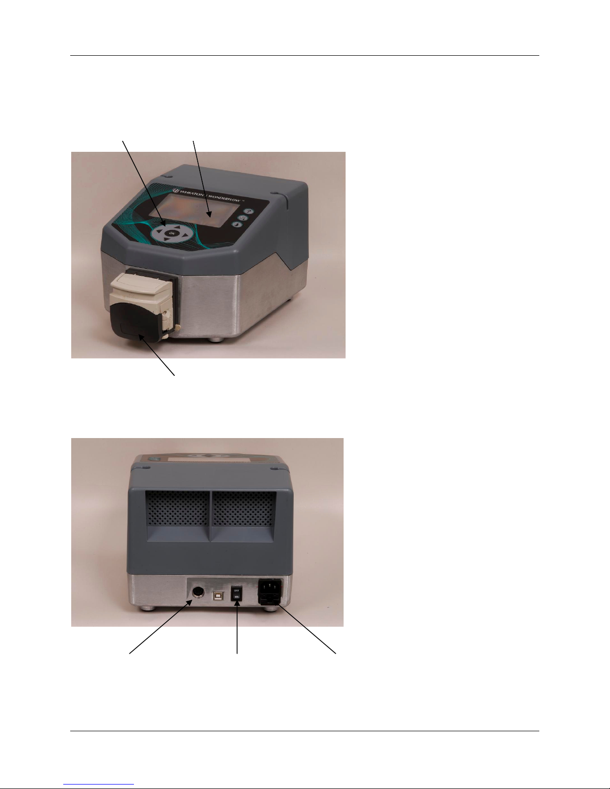
FIGURE A – Major Component Identification
Display Screen Keypad
WHEATON UniSpense® PRO Peristaltic Pump
I/O
Interface
Connector
Pump Head
Power Inlet Module Power Switch
WHEATON | 800.225.1437 (U.S. & Canada Only) | 856.825.1100 | www.wheatonsci.com| P/N 50099073 Rev. 2/2/10 Lit. No.8734
21
Page 22

WHEATON UniSpense® PRO Peristaltic Pump
FIGURE B – Lower Housing Assembly
ITEM USE QTY. WHEATON NO. DESCRIPTION
1
2
3
4
5
6
7
8
9
10
11
12
13
14
15
16
17
18
18
1 50099007 ALUMINUM BASE CABINET
1 WI056857 PCBA, REMOTE I/O
1 WI056858 MOTOR, STEPPER
1 WI056859 UNIVERSAL POWER SUPPLY, 48V, 3.2A
1 50099058 POWER SUPPLY STABILIZER BRACKET
1 WI056856 PCBA, CPU, OMNISPENSE ELITE
1 WI056863 POWER INLET
1 WI056860 POWER SWITCH
4 50099059 ADHESIVE RUBBER FEET
1 50099060 PUMP HEAD DRIVE ADAPTER
2 50029991 SCW, SET, 8-32 X 3/16" LG
4 50099061 SCW, SET, 10-32 X 1/2" LG
4 50099062 SCW, M4X8, SS, PPHM
1 I052239 SCW, 6-32 X 1/4 PPHM
1 50029919 NUT,HEX,6-32
1 I052273 WASHER,STAR,#6,INT TOOTH
1 50099063 STF, 6-32 X 1/4, ALUMINUM
2 WI056864 FUSE, 5X20MM, 2.0AT, 250V (120V)
2 WI056862 FUSE, 5X20MM, 1.0AT, 250V
FIGURES C THRU E – Upper Housing Assembly, Main Assembly and Wiring Diagram
ITEM USE QTY. WHEATON NO. DESCRIPTION
19
20
21
22
23
1 50099005 PLASTIC UPPER HOUSING, CABINET
1 WI056861 LCD, DISPLAY, 240 X 128, BACKLIT
1 50099072 CONTROL KEYPAD OVERLAY, UNISPENSE PRO
4 50099068 SCW, PLASTITE 48, TRILOBE, #4 X 0.250
1 50099006 SCREEN, VENT, PLASTIC
SCW,PLASTITE, 48 TRILOBE, #8 X .750, PPH,
24
25
26
27
28
29
30
4 50099070
1 50099065 ASS'Y, WIRE HNS, OMNI ELITE
1 50028826 LABEL, LINE VOLTAGE
1 50027794 LABEL, UL APPROVED, SERIAL #
1 50028394 LABEL, MET NRTL LISTED, OMNI / FLOW
1 50028414 LABEL, CAUTION
1 50028416 LABEL,CE (MARK) (230V)
STEEL/ ZINC
UniSpense® PRO is a trademark of WHEATON Industries, Inc.
Stylized “W” is a registered trademark of WHEATON Industries, Inc.
Specifications subject to change without prior notice.
2010 WHEATON Industries Inc.
WHEATON | 800.225.1437 (U.S. & Canada Only) | 856.825.1100 | www.wheatonsci.com| P/N 50099073 Rev. 2/2/10 Lit. No.8734
22
Page 23
WHEATON UniSpense® PRO Peristaltic Pump
23
WHEATON | 800.225.1437 (U.S. & Canada Only) | 856.825.1100 | www.wheatonsci.com| P/N 50099073 Rev. 2/2/10 Lit. No.8734
Page 24
WHEATON UniSpense® PRO Peristaltic Pump
24
WHEATON | 800.225.1437 (U.S. & Canada Only) | 856.825.1100 | www.wheatonsci.com| P/N 50099073 Rev. 2/2/10 Lit. No.8734
Page 25
WHEATON UniSpense® PRO Peristaltic Pump
25
WHEATON | 800.225.1437 (U.S. & Canada Only) | 856.825.1100 | www.wheatonsci.com| P/N 50099073 Rev. 2/2/10 Lit. No.8734
Page 26
WHEATON UniSpense® PRO Peristaltic Pump
26
WHEATON | 800.225.1437 (U.S. & Canada Only) | 856.825.1100 | www.wheatonsci.com| P/N 50099073 Rev. 2/2/10 Lit. No.8734
Page 27
WHEATON UniSpense® PRO Peristaltic Pump
27
WHEATON | 800.225.1437 (U.S. & Canada Only) | 856.825.1100 | www.wheatonsci.com| P/N 50099073 Rev. 2/2/10 Lit. No.8734
Page 28

16.0 Declarations of Conformity and WEEE Statement
WEEE STATEMENT
WHEATON UniSpense® PRO Peristaltic Pump
This UniSpense® PRO peristaltic pump is not to be discarded in typical trash outlets. This unit is to be
discarded according to WEEE guidelines established in your area. There are no reusable parts. Contact
the original distributor from which this product was purchased for proper disposal instructions.
WHEATON | 800.225.1437 (U.S. & Canada Only) | 856.825.1100 | www.wheatonsci.com| P/N 50099073 Rev. 2/2/10 Lit. No.8734
28
Page 29

WHEATON UniSpense® PRO Peristaltic Pump
WHEATON Industries Inc.
Declaration of Conformity
We, WHEATON Industries, Inc.
1501 North 10th Street
Millville, NJ 08332-2038
USA
Declare that the device described below - marked with CE - fulfills the relevant fundamental EMC and
safety requirements specified by the appropriate EU - Directive, with respect to the design and
construction of the commercialized version.
This declaration is invalid if modifications are performed on the device
which has not been certified by WHEATON Industries, Inc.
Designation of the device: OmniSpense® ELITE / UniSpense® PRO
Relevant Directives:
Standards:
September 1, 2010
_____________________________ ___________9/1/2010____
Nicholas DeBello, Date
Director, Quality Systems
OmniSpense® ELITE is a trademark of Wheaton Industries Inc.
Stylized “W” is a registered trademark of Wheaton Industries Inc.
WHEATON | 800.225.1437 (U.S. & Canada Only) | 856.825.1100 | www.wheatonsci.com| P/N 50099073 Rev. 2/2/10 Lit. No.8734
29
 Loading...