

Wharfedale Pro WPG-202 Operating Manual
WPG SERIES
PROFESSIONAL
ELECTRONIC
CROSSOVER
WPG-202
OPERATING MANUAL
WPG SERIES PROFESSIONAL E
The WHARFEDALE Wireless Works
was established in 1932 by Gilbert
Briggs who soon established a
reputation as one of the most
innovative loudspeaker
engineers of his generation. His
company was at the leading edge
of an exciting new technology which was dedicated to
bringing the pleasure of music and entertainment into
people s homes. As the technology advanced Wharfedale
gave many music lovers their first taste of High Fidelity,
mounting a series of live sound demonstrations which
excited the audio world and heralded the birth of the ‘
modern hi-fi loudspeaker.
,
Wharfedale Pro WPG series of Electronic Crossovers are
high quality units suitable for stage, club and studio use.
Using proven circuitry they are straightforward to use,
reliable in operation and capable of excellent
performance.
Today Wharfedale Pro takes the same uncompromising
approach to the design and manufacturing of every audio
product, using high-quality components and state-of-theart testing equipment to ensure consistency and high
performance. At Wharfedale we design and build all of our
products and we control all the variables, so that we
,
don t have to compromise our design goals.
Unpacking
All Wharfedale Pro products are fully
checked before leaving the factory. After
unpacking please inspect contents for any
physical damage. Please retain the
shipping carton if possible and internal packing material in case the
unit needs to be returned. Please check as soon as possible the
unit is functioning correctly. In the event of any damage please
contact your dealer immediately so that a written claim for
damages can be made.
Wharfedale Pro Limited Warranty
Wharfedale Pro WPG Series graphic equalisers are warranted to
be clear of defects in construction, materials and malfunction under
normal operating conditions for a period of 3 years from the
original date o purchase providing the unit has only been used for
its intended purpose.
Wharfedale will during the warranty, and at its own discretion,
undertake to make repairs at no charge if the product has been
delivered to Wharfedale Pro by a Wharfedale Dealer.
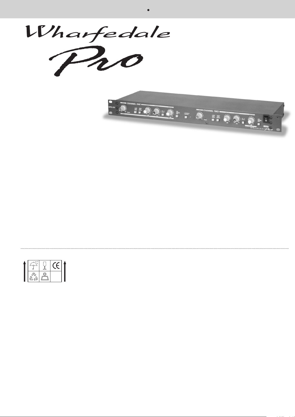
WPG202 Two channel Electronic Crossover
.
Balanced inputs and High Band Low Band outputs with
XLR and jack connectors.
.
Peak level LED indicators
High Pass 40Hz and low pass 15kHz filter circuits
.
Variable controls for gain and frequency adjustment
.
Wharfedale exclude normal exterior wear to finish and cannot be
held responsible for any system malfunction due to abuse or using
the units beyond the limits and conditions as stated within the
specified ratings. Wharfedale shall not be liable for any
consequential damages. Any implied Warranties expire after the
given term.
This warranty is only valid providing:
i) Warranty applies to original purchaser only (warranty not
transferable)
ii) Warranty card must be filled in fully and returned to Wharfedale
Pro within 30 days from date of purchase.
Failure to do so will in no way affect your statutory rights.
iv) Unit must be returned with original sales receipt or other proof
of purchade.
v) Unit is repaired by Wharfedale or authorised service agent only.
These terms do not infringe your statutory rights.

LECTRONIC CROSSOVER MANUAL
3 4 5 6 7 8 9 10 11 12 13 15 16 14 1 2
PLEASE READ THESE IMPORTANT
INSTRUCTIONS.
Safety Instructions
To reduce the risk of electric shock the user should not
remove the cover. All operating and safety instructions
should be followed. The unit should be kept clear of
water, fluids and moisture and not be operated in damp
conditions. The unit should be operated in a well
ventilated environment. The unit should be kept away
from excessive heat sources such as radiators and if
racked with other power amplifiers there should be a
free air flow to vent out the heat produced (check with
dealer). The unit must only be connected to a power
supply as shown on the rear of the unit with the IEC
cable (or similar) provided. The power cord must be
situated or routed so as not to be walked upon or
pinched or objects placed upon it with special attention
to the area where the power cable enters the IEC
socket at the unit. The power cable should be
disconnected during prolonged non usage. The user
should not attempt to service the unit or use the unit in
any way except as described in this manual. For
service and repair your dealer should be contacted.
This unit complies with relevant safety regulations.
POWER NOTICE FOR SAFETY
All British and European countries use a nominally
230v mains power supply. In practise this varies
between 220v and 240v. In the USA the nominal
supply is 115v and 100v in Japan. This unit is set to
the correct voltage in the factory and this can be
checked from the label on the rear panel. If you
intend to use this crossover in a country which has
a different mains supply voltage, you should
consult your dealer for advice. As there are no user
serviceable components inside the crossover, and
high voltages are present, DO NOT remove the
covers! Be sure to make all audio connections to
the crossover before connecting to the mains
supply.
These control no.in the key relate to Mono
operation - in Stereo mode they have same
key descriptions as channel one.
See picture above for key descriptions
1. Power switch should be pressed in to turn on the
power.
2. The Power LED indicates that the unit is ON.
3. Input Level rotary control +10dB gain is available.
4. Peak LED indicates when the input signal is
overloading the equaliser.
5. Low Cut switch enables frequencies below 40Hz to
be attenuated.
6. High Cut switch enables frequencies above 15kHz
to be attenuated.
7. Low level rotary pot controls the level (dB) of the low
frequency as chosen by control 8.
8. Frequency rotary pot selects the crossover point
that occurs between the low and high in stereo mode
and the low and mid in mono mode.
9. x1/x10 switch selects the range of the frequency
rotary pot (no. 8 in the above diagram)
10. The High/Mid out rotary pot controls the level (dB)
of the low/mid frequency as chosen by control 8. This
level control is Mid in mono mode and High in stereo
mode.
11. CD Horn EQ switch enables a fixed equalisation
curve boost at 10kHz implemented on your
compression driver (CD) horn when the switch is
pressed in.
12. Stereo/Mono switch (mono when in )
,
,
13. Stereo/Mono switch LED indicator
14. The High out rotary pot controls the level (dB) of
the high frequency in mono mode and in stereo mode.
15. Only in mono mode This controls the crossover
point between the mid and high units.
16. As no.9 above when in mono mode for high
channel. In stereo mode as no.9 for channel two.
 Loading...