

Page 1
WLA-12
OPERATING MANUAL AND USER GUIDE
www.wharfedalepro.com
Page 2
OPERATING MANUAL AND USER GUIDE
Important Warnings And Safety Instructions
• Read these instructions
• Follow these instructions
• Keep these instructions for future reference
• Heed all warnings
• Do not use this system near water or moisture
• Clean only with a dry cloth
• Install in accordance with these Wharfedale Pro operating instructions
• Follow the manufacturers operating instructions for all peripheral devices such
as ampliers and processors
• Do not install near heat sources such as radiators, heat registers, stoves or
any other apparatus that produces heat (For example lighting systems and
ampliers)
• Use only accessories specied or supplied by Wharfedale Pro
• Do not use shielded microphone/instrument cables to connect ampliers and
speakers, use only approved speaker cables with proper connectors
• Use caution with placement and operation of this speaker system, permanent
hearing damage can be caused by prolonged exposure to excessive sound
ressure levels
p
• Refer all servicing to qualified professionals. Servicing is required when the
loudspeaker has been damaged in any way, such as impact damage, liquid
ingress or foreign object damage. In addition the loudspeaker should be
referred to qualied service personnel if there is any kind of malfunction.
Rigging, suspending and mounting should only be attempted by
experienced qualied professionals. Incorrect usage can result in
damage to equipment and property, injury and even death. Under
no circumstances should you attempt to rig, suspend or mount
these speakers unless you are fully qualied and certied to do
so by relevant local, state and national authorities. If you are not
properly qualied or do not know of pertinent regulations consult
qualified personnel for advice. Consult a structural engineer
before suspending a speaker system and ensure that the total
weight of your system can be held by the truss or mounting
surface.
Inspect all mounting hardware before your line array is own. If there is any
damage or distortion to any mounting hardware do not fly the array until
any damaged hardware is repaired or replaced. Only use Wharfedale Pro
supplied Quick Release Pins, contact your Wharfedale Pro Distributor if any
Quick Release Pins are lost or damaged.
1
Page 3

Contents
WLA Series
Important Warnings And Safety Instructions ...................................................1
Introduction ..........................................................................................................3
Features................................................................................................................4
Splay Angles ........................................................................................................5
Level Tapering .....................................................................................................5
Air Absorption .....................................................................................................6
Full Range Mode ..................................................................................................8
Bi-Amp Mode .......................................................................................................9
Parallel Wiring ....................................................................................................10
WLA-12 Fly Frame ............................................................................................. 11
WLA-12 Dolly .....................................................................................................13
Installation ..........................................................................................................14
Dimensional Drawings - WLA-12 .....................................................................18
Dimensional Drawings - WLA-12 Fly Frame ...................................................19
Dimensional Drawings - WLA-12 Dolly ............................................................20
Example Arrays .................................................................................................21
Specication ......................................................................................................22
Warranty..............................................................................................................22
2
Page 4

OPERATING MANUAL AND USER GUIDE
Introduction
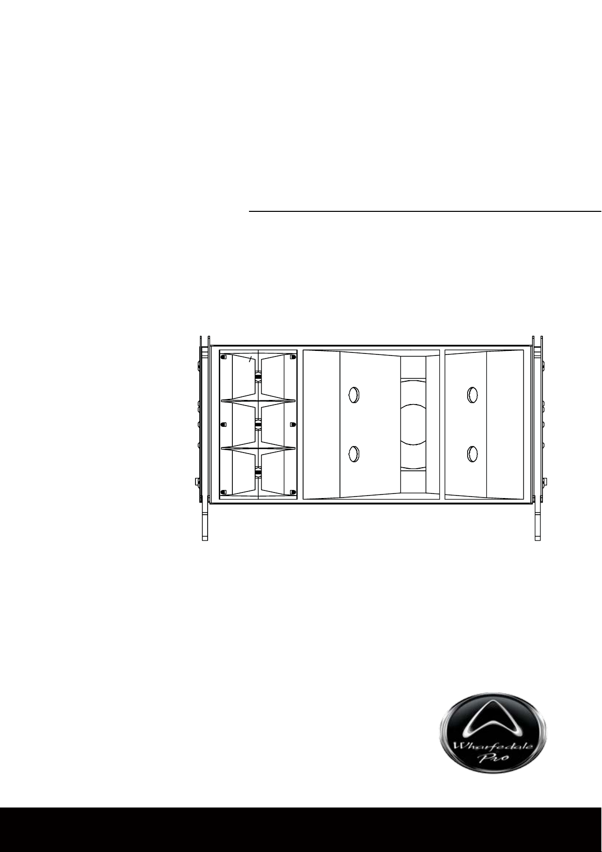
The Wharfedale Pro WLA-12 is a mid format line array system with exceptional
output, frequency response, di rectivity and throw capabili ty. High tech
transducers
size ratio.
The
WLA-12 achieves ultra high sensitivity with its fully horn-loaded architecture.
A horn-loaded 12” LF is combined with three horn-loaded titanium compression
drivers for the HF, generating huge SPL with maximum efciency. The ultra high
sensitivity
of power ampliers, ensuring that your system can generate a huge SPL.
and enclosure design techniques give the WLA-12 a perfect power to
of the WLA Series creates punishing level from even the most modest
Physically
natural intelligibility, clarity and precision without the need for expensive speaker
management. A rear panel bypass setting allows you to use an external active
crossover network or speaker management system to ne tune the system.
hino Rock™, our proprietary ultra tough textured composite finish is used
R
to ensure that the WLA-12 can withstand life on the road, even in the most
demanding touring applications.
A versatile captive, hidden rigging system allows for fast setup with the widest
range of splay angles, while keeping the toughened steel brackets hidden
within the chassis. Inter element splay angles from 0° to 12.5° are possible, a
guarantee
aligned transducers and an internal passive crossover network deliver
that a WLA-12 system can meet the needs of your venue.
3
Page 5

Features
WLA Series
High Sensitivity, Full Horn Loaded Design
400W/800W/1600W Power Handling
12” Horn Loaded LF Driver
3” LF Voice Coil
3x 1” Exit HF Compression Drivers
1.8” Pure Titanium HF Diaphragms With Rare Earth Magnets
Physically Aligned Transducers
Internal Passive Crossover Network
External Crossover Bypass Switching
Front Hinged Rigging System
Captive Rigging Hardware with Tethered Quick Release Pins
Comprehensive Adjustable Splay Angles
Tethered Quick Release Pins (Each Rated To 2000Kg)
Rhino Rock™ Textured Composite Finish
Trapezoid Baltic Birch Plywood Enclosure
2x Parallel Speakon Inputs
4
Page 6

OPERATING MANUAL AND USER GUIDE
Splay Angles
The WLA can be configured with several different splay angles. The splay
angles determine the amount of overlap between individual units. This is used
o determine the amount of summation, or “throw”, for separate sections of the
t
array. As the splay angle between boxes increases the summation decreases but
spectral variance due to interactions between elements is also decreased.
For many venues a good compromise between throw and spectral variance
can be reached by varying the splay angle across the length of the array. By
varying the angular separation along the length of the array a balance can be
m
et for the required coverage. Smaller splay angles provide higher summation
to cover more distant seating and bleachers. Larger splay angles provide lower
summation
can provide even coverage over long distances.
with reduced spectral variance for closer seating. Used correctly this
Each group of loudspeakers with a different splay angle will require a separate
channel of amplification and different EQ settings. This is due to the different
summation effects caused by differing splay angles.
Level Tapering
Tapering the level of enclosures has a beam steering effect which can be used in
conjunction with angular separation between elements. The beam will be steered
away from the “on-axis” center line of the array toward the cabs being driven at
the highest level. The extent of the beam steering effect depends on the length of
the array and the level difference between the top and bottom of the array. This
echnique allows you to further tailor the vertical coverage to differently shaped
t
venues, reducing the level variance between the front and rear of the venue.
Ideally the level of each enclosure is tapered gradually (e.g. 0.5dB or 1dB
per element). This means you will require an amplifier channel per element in
passive mode, or two amplier channels per element in bi-amp mode. Groups of
elements can be tapered in pairs or more, although a more gradual taper will give
you
smoother vertical pattern control.
5
Page 7

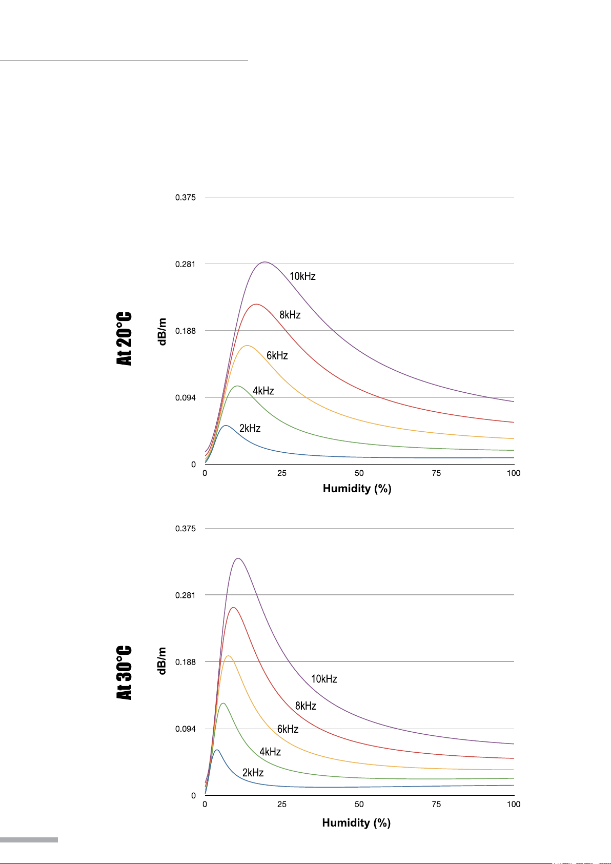
Air Absorption
The high frequency performance of the medium and long throw sections of
the line array will be limited by air absorption. As the distance from the source
increases, the mid and high frequencies will be reduced. The amount of
absorption at a given frequency is a function of pressure, temperature, and
relative humidity. By far the most important factor is the relative humidity,
although temperature does have a signicant effect.
T
of loudspeakers covering the middle to rear of the venue will require equalization
to compensate for this effect. Air absorption is difcult to predict with any great
a
when the audience arrive or the weather changes. It is important that the venue
is monitored during the event as the equalization applied during the design stage
with an empty venue may not be suitable during the event.
WLA Series
o achieve minimal spectral variance across the coverage of the array, the groups
ccuracy, and in any case the relative humidity of the venue is likely to change
As a general guide, boost above 8KHz for a long throw group of loudspeakers,
and
12KHz for a medium throw group of loudspeakers is recommended.
The chart overleaf shows attenuation in dB/m for a given frequency and humidity.
It
is important to note that the effects of air attenuation are linear, unlike the level
attenuation from distance from the inverse square law. For example, at 100m a
source would be 40dB down compared to it’s SPL at 1m. Assuming 50% relative
humidity and 20ºC the level at 10KHz will be an additional 16dB below this
(approximately 56dB down).
6
Page 8
OPERATING MANUAL AND USER GUIDE
Air Absorption
Humidity (%)
7
Page 9

Full Range Mode
WLA Series
8
Page 10

OPERATING MANUAL AND USER GUIDE
Bi-Amp Mode
9
Page 11

Parallel Wiring
WLA Series
10
Page 12

OPERATING MANUAL AND USER GUIDE
WLA-12 Fly Frame
THE WLA-12 AND FLY FRAME IS CERTIFIED TO HOLD A TOTAL
WEIGHT (INCLUDING THIRD PARTY HARDWARE) OF 750KG. 12
ELEMENTS CAN BE FLOWN WITH A SAFETY FACTOR OF 5.7.
Only use the Wharfedale Pro WLA-12 with the WLA Flyframe. Ensure that only
rated, certied hardware such as turnbuckles, shackles and chains are used.
Ensure that all truss, structures and ying hardware are capable of suspending
the entire array, plus ying hardware, to a suitable safety factor.
Rigging, suspending and mounting should only be attempted by
experienced qualied professionals. Incorrect usage can result in
damage to equipment and property, injury and even death. Under
no circumstances should you attempt to rig, suspend or mount
these speakers unless you are fully qualied and certied to do
so by relevant local, state and national authorities. If you are not
properly qualied or do not know of pertinent regulations consult
qualified personnel for advice. Consult a structural engineer
before suspending a speaker system and ensure that the total
weight of your system can be held by the truss or mounting
surface.
Inspect all mounting hardware before your line array is own. If there is any
damage or distortion to any mounting hardware do not fly the array until
any damaged hardware is repaired or replaced. Only use Wharfedale Pro
supplied Quick Release Pins, contact your Wharfedale Pro Distributor if any
Quick Release Pins are lost or damaged.
11
Page 13

WLA Series
12
Page 14

OPERATING MANUAL AND USER GUIDE
WLA-12 Dolly
The WLA-12 Dolly should always be used when flying a WLA-12 line array
system. Each WLA-12 Dolly will hold a single WLA-12 element. The WLA-12
Dolly helps to protect the WLA-12 element and aid the connection and flying
process.
13
Page 15

Installation
One Point Hang Procedure - Method 1
1.
Attach a suitably rated shackle to the center spine of the fly frame. Use
washers to ensure the shackle pin is centered on the spine. The connection
point will depend on the splay angles used in your array and can be used to
aim
the array.
2.
Line up all elements face down on dollies.
3.
Attach the front of the elements to each other with quick release pins.
4.
Attach a Pull Back Bar if required.
5.
Connect signal cables to each element. Take care to ensure that cables of a
sufcient length are used for each connection.
6.
7.
8.
9.
10.
11.
the locking hoist hook to the level of the Fly Frame.
Lower
Attach the locking hoist hook to the shackle on the Fly Frame.
Attach the Fly Frame to the top element using quick release pins.
Raise the hoist to a level that tilts the top element. It should be positioned so
that the quick release pins can easily be inserted through the desired Splay
holes.
Angle
Repeat the process of raising the hoist and attaching the Splay Angle Links of
each consecutive element.
Raise the line array to the desired height.
WLA Series
Two Point Hang Procedure - Method 2
Attach suitably rated shackles to front and rear holes on the center spine
1.
of
the Fly Frame. Use washers to ensure shackle pins are centered on the
spine.
Line up all elements face down on dollies.
2.
Attach the front of the elements to each other with quick release pins.
3.
Connect signal cables to the elements. Take care and ensure that cables of
4.
a sufcient length are used for each connection.
Attach
5.
Attach the Fly Frame to the top element using quick release pins.
6.
Raise the hoist to a level that tilts the top element. It should be positioned so
7.
that the quick release pins can easily be inserted through the desired Splay
Angle holes. (note: raise rear hoist rst)
Repeat t
8.
each consecutive element.
Raise the line array to the desired height.
9.
Adjust the hoists to achieve the desired tilt angle of the array.
.
10
locking hoist hooks to the shackles on the Fly Frame.
he process of raising the hoist and attaching the Splay Angle Links of
14
Page 16

OPERATING MANUAL AND USER GUIDE
Method 1 & 2 Diagram
THE WLA-12 AND FLY FRAME
IS CE R TIF I ED TO H OLD A
TOTAL WEIGHT (INCLUDING
THI R D PARTY HARDWARE)
OF 750KG. 12 ELEMENTS CAN
BE FLOWN WITH A SAFETY
FACTOR OF 5.7.
15
Page 17

WLA Series
Two Point Hang (Limited Space) Procedure - Method 3
1.
Attach suitably rated shackles to the front and rear holes on the center spine
of the y frame. Use washers to ensure the shackle pins are centered on the
spine.
2.
Attach locking hoist hooks to the shackles on the Fly Frame.
3.
Raise the Fly Frame so that the rear connection points are lined up.
4.
Position an element below the Fly Frame and attach the rear of the element
the Fly Frame using quick release pins.
to
5.
Raise the Fly Frame slightly, raise the element and connect the front to the
frame using quick release pins.
6.
Raise the elements again and position another element below it so that the
connection points are lined up.
rear
7.
Now repeat through steps 4-6, before each element is out of reach ensure
that all signal cables have been connected and the length of each one is
adequate.
8.
Raise the line array to the desired height.
9.
Adjust the hoists to achieve the desired tilt angle of the array.
16
Page 18

OPERATING MANUAL AND USER GUIDE
Method 3 Diagram
THE WLA-12 AND FLY FRAME IS CERTIFIED TO HOLD A TOTAL
WEIGHT (INCLUDING THIRD PARTY HARDWARE) OF 750KG. 12
ELEMENTS CAN BE FLOWN WITH A SAFETY FACTOR OF 5.7.
17
Page 19

Dimensional Drawings - WLA-12
WLA Series
�����
������ �
�����
�����
������ �
�����
������ �
������ �
18
Page 20

OPERATING MANUAL AND USER GUIDE
Dimensional Drawings - WLA-12 Fly Frame
THE WLA-12 AND FLY FRAME IS CERTIFIED TO HOLD A TOTAL
WEIGHT (INCLUDING THIRD PARTY HARDWARE) OF 750KG. 12
ELEMENTS CAN BE FLOWN WITH A SAFETY FACTOR OF 5.7.
19
Page 21

Dimensional Drawings - WLA-12 Dolly
WLA Series
20
Page 22

OPERATING MANUAL AND USER GUIDE
Example Arrays
THE WLA-12 AND FLY FRAME IS CERTIFIED TO HOLD A TOTAL
WEIGHT (INCLUDING THIRD PARTY HARDWARE) OF 750KG. 12
ELEMENTS CAN BE FLOWN WITH A SAFETY FACTOR OF 5.7.
21
Page 23

Specication
System Specication
System Type
Frequency Range (-10dB)
Frequency Response (±3dB)
Sensitivity (1w@1m)
Peak SPL
System Impedance
Power Handling
Continuous
Music
Peak
LF Driver
Driver Size
Frame Material
Impedance
Quantity
HF Driver
Driver Size
Frame Material
Impedance
Quantity
Enclosure
Dimensions
(L)
Front (W)
Back (W)
(H)
Enclosure Type
Finish
Finish Colour
Construction Material
Thickness
Grille
Input Connectors
Carton Dimensions
(L)
Front (W)
Back (W)
(H)
Weight
Net Weight
Gross Weight
WLA-12
Range
Full
47Hz-18kHz
65Hz-18kHz
102dB
134dB
8Ω
400w
800w
1600w
305mm / 12"
Al
8Ω
1
45mm / 1.8"
Al
24Ω
3
930mm / 36.6"
483mm / 19.0"
376mm / 14.8"
489mm / 19.2"
Trapezoid
Paint
Black
Plywood
15mm
Black Steel
2 X Parallel Speakon
1025mm / 40.3"
585mm / 23.0"
530mm / 20.9"
580mm / 22.8"
61Kg / 134.2lbs
73Kg / 160.6lbs
WLA Series
WHARFEDALE PRO LIMITED WARRANTY
Wharfedale Pro products are warranted of manufacturing or material defects for a period of one year from
the original date of purchase. In the event of malfunction, contact your authorized Wharfedale Pro dealer or
distributor for information.
*Be aware that warranty details may differ from country to country. Contact your dealers or distributor for
information. These terms do not infringe your statutory rights.
22
Page 24

Wharfedale Professional
IAG House, 13/14 Glebe Road, Huntingdon, Cambridgeshire, PE29 7DL, England
www.wharfedalepro.com
Wharfedale Professional reserves the right to alter or improve specications without notice.
All rights reserved © 2013 Wharfedale Pro. Wharfedale Pro is a member of the IAG Group.
 Loading...