

Page 1
STEREO CAR MP3 CD
RECEIVER
INSTRUCTION MANUAL
WCA7393F
EON • PTY • CT
Page 2

2
INSTALLATIONS
• Use only the supplied mounting hardware for a safe and secure installation.
PRECAUTIONS
• This unit is designed for negative ground 12-V DC operation only.
• Before installation, make sure the ignition switch is set to OFF and disconnect the ground terminal
of the car battery to avoid short-circuiting.
• Install the unit where it will not hamper the driver during driving.
• Install the unit where it will not injure the passenger if there is a sudden stop, like an emergency
stop.
• Avoid installing the unit where it would be subject to high temperatures caused by direct sunlight
or hot air from the heater, or where it should be subject to dust, dirt or excessive vibration.
• Use only the supplied mounting hardware for a safe and secure installation.
Consult with your nearest dealer if installation require the drilling holes or other modifications of your
car.
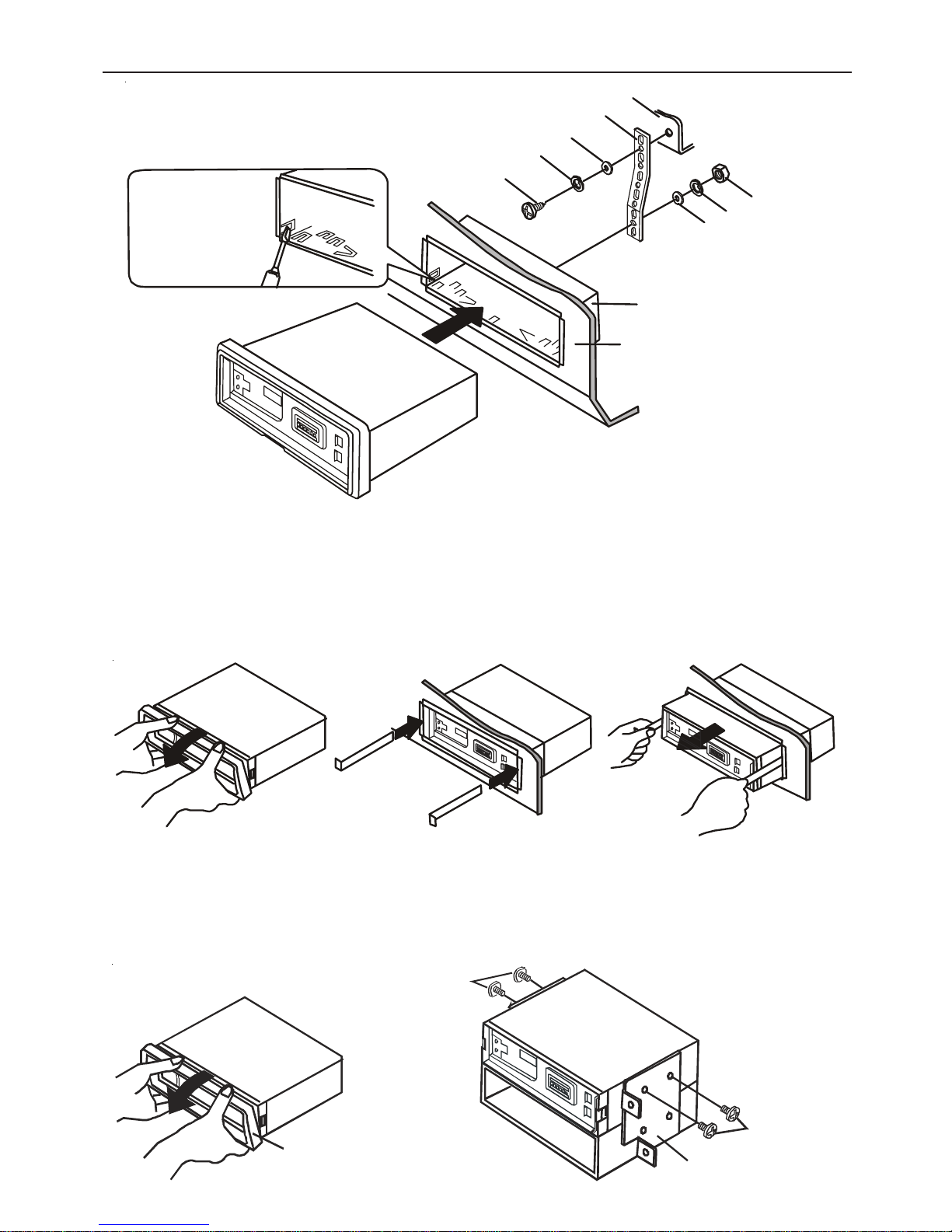
MOUNTING EXAMPLE
Installation in the dashboard
The following example shows a typical installation, however you should make adjustments
corresponding to your specific car, consult your nearest car audio dealer.
Mounting angle adjustment
The mounting angle should be at the angle of 30 degrees or less.
REMOVING EXISTING RECEIVER UNIT
If there is an installation sleeve for the receiver unit already in the dashboard, it must be removed.
NOTE:
Take out two screws on the top of unit before
installation.
Supporter x 1
Ins ta ll at io n sl ee v e x 1
Nut x 1
Screw x 1 Washer x 2 Spring washer x 2 Lever x 2
Existing receiver unit
Installation sleeve
Dashboard
Page 3
3
Mount the unit
INSTALLATIONS
When removing the unit from the installation sleeve
If you need to remove the unit from the installation sleeve, proceed as follows:
1. Remove the rear supporter from the unit.
2. Remove the control panel from the unit. (Refer to the operating instructions.)
3. Remove the trim from the unit.
4. Insert two levers into the pair of grooves on both sides of the unit, and pull the levers toward you
to remove the unit from the installation sleeve.
INSTALLATIONS WITHOUT USING THE SLEEVE
In the case of Toyota cars, etc., first remove the existing car stereo and then install the unit in its place.
1. Remove the trim plate in the direction of the arrow.
2. Attach the existing mounting bracket (not supplied) to the unit. Make sure to use the screws (M5 x
8 mm) (not supplied). Using longer screws may damage the unit.
Screws
(M5 x 8mm)
Screw
s
(M5 x 8mm)
Mounting bracket
Trim plate
Dashboard
Installation sleeve
Fire wall
Note
Bend the claws
according to the
thickness of the
dashboard.
Screw
Spring washer
Washer
Washer
Supporter
Nut
Sprin g wa sher
Page 4

4
CONNECTIONS
4
Reset button
CONNECTION DIAGRAM
From Antenna
To the ISO connector of vehicle (power supply)
Note
If you want to use the leads with the ISO connector removed,
make sure to connect each lead to the correct terminal
according to the list of colours of leads below.
Colours of leads
1. Black (ground lead to be connected to vehicle (metal)
body).
2. Red (ACC lead to be connected to the terminal from
which the power is supplied when the ignition switch is
set to ACC).
3. Orange/White (power antenna lead to be connected to
the terminal of the control relay switch for vehicles
equipped with a power antenna. This lead is not used for
vehicles with manual or semiautomatic antennas. When
you use optional power amplifiers with the unit, connect
this lead to the remote terminal of the amplifier).
4. Orange (battery lead to be connected to the backup
terminal from which power is always supplied).
To the ISO connetor of vehicle (speaker connection)
Note
If you want to use the leads with ISO connector removed,
make sure to connect each lead to the correct terminal
according to the list of colours of leads below.
Colors of leads
5. Brown/Black with Black Stripe (Rear left )
6. Grey/Black with Black Stripe (Front left )
7. White/Black with Black Stripe (Front right )
8. Yellow/Black with Black Stripe (Rear right )
9. Brown (Rear left )
10. Grey (Front left )
11. White (Front right )
12. Yellow (Rear right )
Notes
• Use speakers with an impedance of 4 to 8 ohms, and
with adequate power handling capacities. Otherwise,
the speakers may be damaged.
• Do NOT connect the speakers in parallel.
• Do NOT connect the terminals of speaker system to the
car chassis.
RESET SWITCH
• Press reset switch once, after making all connections.
If your vehicle is
not fitted with this type of connector you
must purchase the accessory pack available from your car
radio realer.
Precaution on making connections
Before connecting, make sure that the ignition switch is set
to OFF, and remove the terminal of the battery to avoid
short circuits.
Caution
Make correct connections as illustrated in the connection
diagram.
Never use the cord of each speaker in common. When
replacing the fuse, be sure to use one whose amperage
rating is identical. Use of a fuse of higher amperage may
cause serious damage to the unit.
This unit is designed for negative ground 12-V DC operation
only.
NEVER! Connect the cord of each speaker in common
to ground.
A
B
C
ATTENTION
A
B
C
0.5A
5
9
6
10
11 12
78
1
GROUND
2
ACC
3
AUTO ANT
4
BACK UP B
Page 5

5
5
BEFORE USE
NOTE
In addition to this operating instructions manual,
be sure to refer to the labels on the unit as well.
PRECAUTIONS
• This unit is designed to be operated on a 12-
volt DC negative-ground electrical system only.
• To prevent short-circuiting, disconnect the nega-
tive car battery terminal until the unit has been
mounted and connected completely.
• When replacing the fuse, be sure to use one
whose amperage rating is identical. Use of a
fuse of higher amperage may cause serious
damage to the unit.
• Do NOT attempt to disassemble this unit. Laser
rays from the optical pickup are dangerous to
the eyes.
• Make sure that pins or other foreign objects do
not get inside the unit; they may cause malfunctioning, or a safety hazard such as electrical shock or exposure of laser rays.
• If you park your car in direct sunlight it may
result in a considerable rise in temperature inside the car. Allow the car to cool off before
operating the unit.
• Keep the volume at such a level that you can
hear outside warning sounds (horns, sirens, etc.).
• The apparatus shall not be exposed to dripping
or splashing.
CAUTION
Modifications or adjustments to this product, which
are not expressly approved by the manufacturer,
may void the user's right or authority to operate
this product.
NOTE ON CDs
• A defective or soiled disc inserted into the unit
can cause sound to drop out during playback.
• Handle the disc by holding its inner and outer
edges.
• Do NOT touch the surface of the unlabeled
side of the disc.
• Do NOT stick paper or tape etc. on the surface.
• Do NOT expose the disc to direct sunlight or
excessive heat.
• Clean the disc before playback. Wipe the disc
from the centre outward with a cleaning cloth.
• NEVER use solvents such as benzine or alcohol
to clean the disc.
• Smaller 3-inch (8cm) CDs can not be played on
this unit. And do not use adaptor as it may cause
malfunctioning.
• Do not use irregular shape CDs (example :
heart -shaped, octagonal ones). It may result in
malfunction.
INCORRECT WIRING.
The manufacturer is not responsible for any
defect that may occur due to incorrect wiring
of this product.
Never connect the cord of each speaker in
common to ground.
• This unit is designed only for negative ground 12V DC operation. The equipment can be used safely
if the negative terminal of the battery is connected to the vehicle metal work.
• Do not use speakers of impedance less than 4 ohms and do not allow the speaker wires to be shorted
together when the unit is switched on, otherwise it may overload or burn out the power amplifier
stage.
• If the car interior is extremely hot, for example after being parked in the sun, do not use the player
until the car has been driven for a while to cool off the interior.
Caution Vauxhall owners:
Vauxhall do not follow the normal ISO wiring convention which will cause the unit to lose the radio
preset memories each time the ignition switch is turned off. To prevent such occurrences swap over the
Red ignition and Orange Memory wires in the bullet connectors attached to the wiring harness of the car
radio.
PRECAUTIONS AND MAINTENANCE
IMPORTANT NOTE:
* This unit develops high power output to the front speakers. It is very important that you confirm the
front speakers fitted in your vehicle are capable of handling this power.
* If after directly connecting the unit via the vehicles ISO connector plugs it does not appear to work
(fails to power up), disconnect the Orange lead bullet connector and reconnect it to the twin bullet
connector socket on the RED wire. Try the unit again it should power up and can be used normally.
Note this phenomenon is most frequent in Volkswagen/Audi and Vauxhall vehicles.
Page 6

6
NAMES OF CONTROLS
MAIN UNIT
DISPLAY WINDOW
1. OPEN button (for disc compartment)
2. VOLUME control
3.
CD eject button
4. Display window
5. BAND/AMS(auto memory/preset scan) button
6. MODE button(Tuner/CD mode)
7. DISP (display) button
8. POWER (power on/off) button
9. Disc compartment
10. (forward skip)/ (tune up) button
11.
(back skip)/ (tune down) button
12.
Panel release button
13. TA (traffic announcement) button
14. PTY (program type) button
15. AF (alternative frequency) button
16. Preset station buttons (1~6)
17. +5 (five tracks up) button
18. -5 (five tracks down) button
19. RND (random) button
20. INT (intro-scan) button
21. RPT (repeat) button
22. PAUSE button
23. MUTE/LOUD (loudness) button
24. SEL/DIM (select/dimmer) button
25. Level indicator
26. LOCAL indicator
27. REG (region) indicator
28. LOUD (loudness) indicator
29. Stereo indicator
30. CD play indicator
31. AF (alternative frequency) indicator
32. TA (traffic announcement) indicator
33. TP (traffic program) indicator
34. EON (enhance other network) indicator
35. PTY (program type) indicator
36. MP3 indicator
37. CH (channel)/preset number indicator
38. Main display section
123 4 5678
9
10
11
12
131415161718192021222324
CH
AUX
LOCAL REG LOUD
AF TA TP EON PTY
25 26 28 29 30 31 32 33 34 35
36
3738
27
Page 7

7
DETACHING AND ATTACHING THE FRONT PANEL
TO DETACH THE FRONT PANEL
1.
Switch off.
Before detaching the panel, remove the disc to
prevent possible damage to the unit.
3.
Press the panel release button to
detach the panel.
4.
Lift and pull the front panel out of the main
unit.
Put the front panel in the provided case for
protection.
TO ATTACH THE FRONT PANEL
1.
Insert the left side of the front panel into the
groove on the left side of the holder.
2.
Press the right side to set it correctly.
Security Lamp
When the car's ignition is turned off with the front
panel detached, you can find the LED lamp on
the front side of the unit. This lamp is designed to
deter theft, and continues to light. This unit is not
equipped with any other security systems such as
security alarm, so there are limitations to its
effectiveness.
LED lamp
2.
Press open button to slide down the front
panel and then press the CD eject button to
eject the disc.
• Do NOT touch the connector on the reverse
side of the front panel, as doing so may
contaminate the connector and cause a poor
connection resulting in a malfunction.
OPEN
Push to close the
CD compartment
Page 8

8
SETTING THE CLOCK
1.
Switch on.
2. Press DISP to select clock mode and then hold
DISP for more than 2 seconds.
3.
Press to set the hour
Adjust.
Press to set the minutes.
4.
Press DISP.
The clock starts working.
Having the clock displayed while in Radio or
CD Play mode.
Press DISP button until the clock is displayed. To
return to its former display, press DISP again.
Each time you press DISP, the display changes as
follows.
Radio mode:
CD mode:
Remark:
Once the RDS CT (Clock Time) is received from
a broadcasting station, the manual adjustment is
disabled until the reset button is pushed again.
Frequency
PS indication (option)
Clock
Clock
CD Track no. + track time
ACTIVATING THE OPERATING
TONE (BEEP)
The operating tone can be activated or
deactivated.
Activating the operating tone
Press and hold the POWER button for 2 seconds
until "BEEP ON" is displayed. The operating tone
will beep when an operating button is pressed.
Deactivating the operating tone
Press and hold the POWER button until "BEEP
OFF" is displayed.
Note:
The operating tone's status-activated (BEEP ON)
or deactivated (BEEP OFF) - will be stored in
memory even when the power is turned off.
Page 9

9
RADIO OPERATION
1.
Switch on.
FM1, FM2, FM3 have the same frequency
range. MW1, MW2 have the same frequency
range.
Press BAND button to select band.
Press to seek frequency up.
Tune.
Press to seek frequency
down.
Press tune up
button or tune down
button more than 0.5 second, the unit starts
scanning and tunes in a station automatically
(Seek tuning).
Adjust volume.
To turn the unit off
Press POWER button.
NOTE:
The "((ST))" stereo indicator lights up when the
tuned in station is broadcasting in stereo and the
reception is good.
Select band.
The tuner will automatically store up and scan 6
stations in each band FM1, FM2, FM3, MW1 and
MW2 (up to a total of 30 stations).
• When auto memory storing is completed, the
selected stations are automatically stored and
shown in order.
• To stop auto memory, press BAND/AMS button
again.
LISTENING TO THE RADIO
STORING THE STATIONS IN
MEMORY AUTOMATICALLY
2.
3.
Switch on.
1.
Press and hold BAND/AMS
button for more than 2
seconds to activate the
automatic store function.
Band Frequency
3.
2.
AMS
AMS
FM1 FM2 FM3
MW2 MW1
FM1 FM2 FM3
MW2 MW1
AMS
Page 10

10
MANUAL STATION PRESET
Press BAND button to select band.
1.
3.
4.
Press one of the preset station buttons 1 to 6
for approximately 2 seconds.
The current station is stored in preset memory
bank. The number of the pressed preset station
button appears next to the frequency indication.
Repeat these procedures to preset up to 6 stations
each for FM1, FM2, FM3, MW1 and MW2.
• You can manually preset station that have not
been selected by auto memory.
• If you try to preset a station on a preset station
button on which another station of the same
band has already been preset, the previously
preset station will be erased.
Switch on.
2.
PRESET STATION TUNING
Press BAND button to select band.
1.
Switch on.
2.
3.
Press the desired preset station button less 2
seconds.
The number of the pressed preset station button
appears next to the frequency indication.
Active tuning reception control (ATRC)
This unit automatically suppresses FM stereo noise
caused by varying signals strength resulting from
movement of the car.
• The built-in automatic blending circuit mixes
the left and right channel signals according to
the strength of the reception. At the same time,
the high-cut circuit activates to maintain the
sound quality.
• If the reception becomes even weaker, the unit
automatically switches to Monaural mode to
reduce noise.
RADIO OPERATION
Press to seek frequency up.
Tune.
Press to seek frequency
down.
Preset number
AMS
AMS
FM1 FM2 FM3
MW2 MW1
FM1 FM2 FM3
MW2 MW1
Page 11

11
What's RDS?
Developed by the European Broadcasting Union
(EBU), the Radio Data System (RDS) offers
listeners various information services, such as
station name display and traffic announcements
through FM broadcasting.
Since the RDS data is in digital form, you cannot
hear it. This means you can receive FM programs
without being disturbed by RDS data signals.
This receiver can receive the following types of
RDS digital data:
• PS (Program Service) name
Displays the station name during reception.
• AF (Alternative Frequencies)
Automatic tuning to alternative frequencies.
• TP (Traffic Program)
Automatic traffic announcement reception in
the CD mode as well as Tuner mode.
• PTY (Program Type)
Program selection by program type, such as
news, sports, rather than by station.
• EON (Enhanced Other Network)
Switches automatically when a traffic
announcement begins on an outside network.
Press AF, the information is updated
automatically.
Note:
EON indicator turns on when that station received
contains EON information. The EON information
helps the receiver to check other network
(stations) traffic program status.
IMPORTANT
• These RDS functions are effective only in FM
(FM1, FM2 and FM3) mode.
• The above functions may not operate correctly
where RDS transmissions are in the
experimental stages.
Displaying the station name
If the received station has a program service name,
the station name is displayed.
• The station name may not be displayed if the
signal is below a certain level.
Receiving alternative frequencies
When the FM program tuned in is being broadcast
on network stations, you can continue to listen to
that program while driving without frequent
manual retuning.
USING RDS FEATURES
During FM reception, press AF to turn on the AF
indicator.
• If the station tuned in does not offer AF data,
the AF indicator blinks.
The unit searches for an alternative frequency
which has the strongest signal among the network
stations and immediately retunes to that frequency.
For example, if the program tuned in is broadcast
in 88.0 MHz, 88.5MHz and 90.1 MHz as shown
in the illustration above, the tuned-in station
frequency will change to 88.0 MHz, 90.1 MHz
and 88.5 MHz as the car moves.
If no alternative frequencies are found, press AF
to leave the AF mode.
Regional
Press AF button and hold for 2 seconds to change
Regional status.
"REG ON" means alternative frequency PI code
must be exactly identical.
"REG OFF" means the region identification code
in the PI code is ignored so that the local station in
one area can be changed to another station (eg.
"BBC Kent" changed to "BBC Slnt") in an other
area.
88.0 MHz
90.1 MHz
88.5 MHz
Station name
Page 12

12
USING RDS FEATURES
Receiving traffic announcements
Once the unit is set in the TA (traffic announcement)
Standby mode, you can hear traffic announcements
as soon as they begin, even if you are listening to
CD.
1. Tune in an FM station.
2. Press TA to turn on the TP indicator and enter
the TA Standby mode.
If the tuned-in station does not offer traffic
announcement service, the TP indicator blinks.
In this case, tune in another FM station with TA.
3. Listen to the radio or CD.
When a traffic announcement starts, the unit
automatically enters the FM reception mode, and
the TA indicator flashes. The frequency indicator
also displays the station name a few seconds later.
When the announcement is finished, the TA
indicator ceases to flash and the original source
will be heard.
Traffic announcements are heard at a preset level,
regardless of the volume setting. This is convenient
when you want to hear no other sources other
than the traffic announcement.
If the level of an alternative frequency falls below
a certain level, both the AF and TP indicators blink.
This function switches in automatically when a traffic
announcemnet has begun on another network, so
you can listen to the traffic announcement.
Receiving traffic announcements during CD play
Press TA to turn on the TP indicator. The unit will
search for the TP station which has the strongest
signal without disturbing CD play.
When a traffic announcement starts, CD pauses
and you can hear the announcement. When the
announcement is over, CD play resumes.
Note
If the CD player is in the repeat or random, play
mode before a traffic announcement begins, normal
CD play will resume after the announcement is
finished.
• Press TA to turn off traffic announcements and
return to CD. This clears the TA mode and
returns to the CD mode.
Selecting FM by program type
This feature may not yet be available in your
area. During FM reception, press PTY.
The unit enters the PTY mode and PTY type will
turn on in the display for about 5 seconds.
When
/ or / button is kept
pressed, the program type starts to change
automatically. Then release the button.
Select the program type
1. Turn on the power.
2. Tune to the desired band.
3. Press PTY. Program type will turn on in the
display for about 3 seconds.
4. Within 3 seconds, press / or /
button to display the desired program type.
5. Press PTY and hold for 2 seconds to start.
1. NEWS 30. ALARM !
2. AFFAIRS 29. DOCUMENT
3. INFO 28. FOLK M
4. SPORT 27. OLDIES
5. EDUCATE 26. NATION M
6. DRAMA 25. COUNTRY
7. CULTURE 24. JAZZ
8. SCIENCE 23. HOBBIES
9. VARIED 22. TRAVEL
10. POP M 21 . PHONE IN
11. ROCK M 20. R ELIGI ON
12. M_O_R_M 19. SOCIAL A
13. LIGHT M 18. CHILDREN
14. CLASSICS 17. FINANCE
15. OTHER M 16. WEATHER
Page 13

13
1.
Switch on.
2.
SEL (select) button
Select the control mode with
the SEL button.
The following indications appear in cyclic order:
BAS (bass), TRE (treble), BAL (balance), FAD
(fader), TAVOL (TA volume), VOL (volume).
The selected mode switches to normal mode if you
do not proceed with step 2 within 3 seconds.
3.
Turn VOL (volume) control
to change the level rapidly.
ADJUSTING THE SOUND CHARACTERISTICS
MUTE button
Press the MUTE button to
temporarily cut the volume.
"MUTE ON" appears.
Press it again to restore the
previous volume. "MUTE
OFF" appears for a few
seconds.
Loudness function
Press the MUTE / LOUD
button more than 2 seconds to
turn "LOUD ON" to reinforce
bass especially when listening
at low volume level.
Press MUTE / LOUD button
more than 2 seconds again to
turn "LOUD OFF".
ADJUSTING THE DISPLAY
BRIGHTNESS
When the unit is on, press the SEL/DIM (dimmer)
button more than 2 seconds to activate dimmer
function. The display changes brightness in HIGH
-> MEDIUM -> LOW.
Adjust each mode referring to the audio control
indications in the display window.
The range of Volume level is displayed as a
number from 0 to 63 (MAX).
Bass level: -12 to +12.
Treble level: -12 to +12.
Balance level: R15 to L15
Fader level: R15 to F15
TA volume level: 0 to 63
Without selecting any mode with SEL, only
the volume level can be adjusted by tuning
VOL control.
Page 14

14
PLAYING COMPACT DISCS
1.
Press OPEN button and insert the disc with the
labeled side upward.
(When the disc is inserted part-way, it is drawn
in and play starts automatically.)
Close the disc compartment by pushing the
bottom of the front panel.
The track number and track timer appear.
2.
Adjust volume.
To pause playback
• Press 1/PAUSE button. To resume playback,
press 1/PAUSE button again.
Repeat playback
• Select desired track to be played repeatly by
pressing / button.
• Press 2/RPT (repeat) button to start repeat one
play. "RPT ON" is displayed for a few seconds.
Press 2/RPT button again will cease repeat play.
"PRT OFF" is displayed for a few seconds.
Note: If repeat play is not activated, all the tracks
on the disc are played repeatedly.
Intro scan play
(Playing the first ten seconds of all the selections)
• Press 3/INT (intro scan) button to start playback.
Pressing 3/INT button again will cease the intro
play.
Track number Track timer
Random play
(Playing the selections in random order)
• Press 4/RND (random play) button to start
random play. "RDM ON" is displayed for a few
seconds.
Pressing 4/RND button again will cease random
play. "RDM OFF" is displayed for a few seconds.
5 tracks up / 5 tracks down
• Press 5/-5 button to access 5 tracks down.
• Press 6/+5 button to access 5 tracks up.
Press MODE button to select CD mode.
Push to cl ose the
CD compartment
Slide down the front panel to insert a
disc.
Eject a disc.
Skip to the next track with a short press
(for less than 0.5 seconds).
Each extra press skips forward one extra
track.
To search forward rapidly, press and
hold
down until the desired part
is played, then release it.
Restart the track currently in play with
a short press (for less than 0.5 seconds).
Each extra press skips backward one
extra track.
To search backward rapidly, press and
hold
down until the desired part
is played, then release it.
Note
• Smaller 3-inch (8cm) CDs can not be played
on this unit. And do not use an adaptor as it
may cause malfunctioning.
Press To
Press these buttons to operate CD play.
Page 15

15
Cleaning the front panel
When the front panel is soiled, wipe the surface of
the panel with a dry and soft cloth.
Cleaning the connector
The connector on the reverse side of the front
panel needs to be cleaned occasionally. Wipe
the surface of the connector with a cotton swab
slightly moistened with alcohol.
MAINTENANCE
RESET BUTTON
The Reset button is visible when you detach the
front panel. Try pressing this button if the unit does
not operate properly. When you press this button,
use the tip of a pointed object such as a pencil or
toothpick.
Note that the memory contents, however, will be
erased by pressing this button.
TROUBLE SHOOTING
NOTE:
When a disc in the CD compartment
1. Press
OPEN button to slide down the front
panel.
2.Press
CD eject button for more than 2
seconds, the disc will be ejected.
Reset button
MP3 FILE DISC PLAYBACK
Insert a MP3 file disc. The unit starts to read the
disc. After reading disc, track no. & playing time
are shown and playing starts. MP3 indicator will
light while MP3 files are playing.
• In MP3 mode, press the
/ or /
button to select the files.
• Press and hold the / or / button
for more than 2 seconds to access MP3 next
folder up or down selection.
Other operations are same as playing CD.
The ability of this Unit to read MP3 discs is
dependent on the following:
• The Bit Rate must be within 64 - 256 kbps.
• The total number of files on the disc should
not exceed 254.
• When recording on CD-R discs, use 74-
minute (650MB) discs.
• The CD-R or CD-RW discs should be
“finalized” in computer by “single session
format”.
• Only MP3 files put in CD-ROM will provide
shortest searching time.
• See your CD/MP3 creation software for
details.
Page 16

SPECIFICATIONS
RADIO SECTION
(FM)
Frequency Range: 87.5 MHz - 108 MHz (50-kHz step)
50 dB Quieting Sensitivity: 17.2 dBf
IF Rejection: 80 dB
Frequency Response: 30 Hz-15,000 Hz
S/N Ratio: 63 dB
Stereo Separation: 35 dB at 1 kHz
Alternate Channel Selectivity: 70 dB
Capture Ratio: 3 dB
(MW)
Frequency Range: 522 kHz-1,620 kHz (9-kHz steps)
Usable Sensitivity: 30 µV (20 dB)
CD SECTION
Frequency Response: 17 Hz-20 kHz +0/-3 dB
Dynamic Range: More than 80 dB
Channel Separation: More than 65 dB
S/N Ratio: More than 85 dB
Wow/Flutter: Unmeasurable
AUDIO SECTION
Max. Power Output: 40 W x 4 channels
GENERAL
Power-Supply Voltage: 14.4V (11 to 16V allowable) DC, negative ground
Current Drain: 15 Ampere (max.)
Load Impedance: 4 Ω − 8Ω
Tone Control: Bass ± 10 dB at 100 Hz
Treble ± 10 dB at 10 kHz
Installation size: 182(W) x 53(H) x 155(D) mm
(7¼(W) x 2
1
8
/
(H) x 6
1
8
/
(D) inches)
• Specifications and external appearance are subject to change without notice due to product improvement.
811-739391W022
Waste electrical and electronic products must not be
disposed of with household waste. Please refer to the
retailer from whom you purchased this item for
disposal instructions.
Argos MK9 2NW
Product Guarantee
This product is guaranteed against manufacturing defects for a period of 1 Year.
This does not cover the product where the fault is due to misuse, abuse, use in contravention of the
instructions, or where the product has been the subject of unauthorised modifications or alterations, or
has been the subject of commercial use.
In the event of a problem with the product within the guarantee period please return it to your nearest
store.
If the item is shown to have had an inherent defect present at the time of sale, the store will provide you
with a replacement.
Your statutory rights remain unaffected.
Guarantor; Home Retail Group, 489 – 499 Avebury Boulevard, Central Milton Keynes MK9 2NW
 Loading...