

Page 1
Getting the Best From Your Loudspeakers
PHASE
If the sound lacks definition or the bass is indistinct, the
speakers could be incorrectly wired (out of phase). If this is the
case please check the wiring to the panels carefully.
ANCILLARY EQUIPMENT
Wharfedale speakers are compatible with the great majority of
high fidelity equipment currently available - but a loudspeaker
is only as good as the signal it gets. The quality of your source
CARE AND MAINTENANCE
equipment is critically important.
Very little maintenance is required. The Picture Panel frame and
RUNNING IN
the surface of the panel can be occasionally wiped clean with a
Like all mechanical systems, loudspeakers to be 'run in'. For the
soft, damp (not wet) cloth. Do not use detergents or solvents.
first 50 hours or so play your system at reasonable volume
Use an appropriate method if you have applied your own
levels. After running in, you will notice a sonic improvement,
picture. The cabinet of the sub-bass unit should be cleaned
especially in the sub bass unit.
with a soft damp cloth.
CONNECTING WIRES
Avoid trailing cables across open floor spaces where they can be
a source of danger. Route cables safely under carpets or along
room boundaries.
When mounting a panel on a wall the connecting cables may be
unacceptably obvious. Whilst the flat cable would normally be
routed from the panel to the floor, it may be less obtrusive to
route cables from the panel to the ceiling and then within or
immediately underneath the ceiling (or coving).
Specifications
8 Ohms
70 Watts
87dB
(DML connection)
160Hz - 20KHz
160Hz
35Hz
555 x 500 x 27
21.8 x 19.7 x 1.1
PPS 1 Panel
Service & Information
8 Ohms
70 Watts
87dB
40Hz - 160Hz
235 x 460 x 210
9.25 x 18.1 x 8.26
LP1 Sub-Bass
Television picture is distorted or there is colour
distortion
The LP 1A sub bass unit is too close to the TV. (Switch off the system and
TV. Move the sub bass away. Leave 20 mins. Switch on again)
Excessive, distorted bass at high volumes
Master level set too high, Bass control set too high
Sound consists of just bass frequencies
No treble from one channel
Check connections and cables
The protection device on one or both PPS 1 panels has operated.
Turn down the volume control on your audio system until full output is
resumed.
Indistinct sound
One or more loudspeakers is out of phase
(See this manual for the connection procedure)
Distorted or rattling sounds at high volume levels
System level set too high
Objects placed on sub bass unit
Bass distortion at low volume levels
Volume from source unit set too high
Sub bass inputs connected to amplifier loudspeaker outputs
Sound lacks bass content
Check the connections from sub bass unit to panels
No sound at all
Are al lunits turned on and working ok.?
Check all connections and cables.
Ensure there are no short circuits across terminals.
Symptom Possible Cause
The name WHARFEDALE' is a registered trademark of Wharfedale International Limited.
Wharfedale has a policy of continuous product development and reserves the right to change specification without notice.
Wharfedale is a member of the International Audio Group.
Product service enquiries should, in the first instance, be referred to the
supplying dealer. In cases of difficulty or for other product enquiries
please contact the appointed Wharfedale distributor for the country.
IAG America, Inc.
15 Walpole Park South
Walpole
MA 02081
Tel: +1 508 850 3950
USA
UK
(and information on all territories)
Wharfedale International Ltd.
IAG House, Sovereign Court,
Ermine Business Park, Huntingdon,
Cambs PE29 6XU, England.
Tel: +44 (0)1480 447700
Fax: +44 (0)1480 431767
www.wharfedale.co.uk
2 x 25mm Exciter 170mm Bass
Customising the PPS 1 Panels
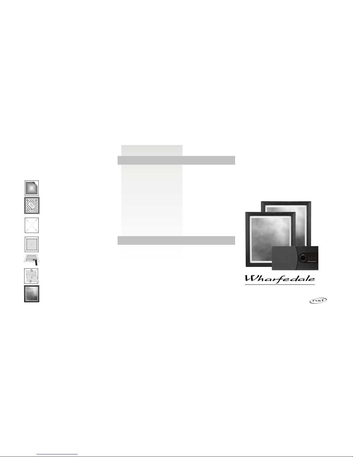
The PPS 1 Panel can be customised with your choice of graphics.
For a small charge most high street picture specialists will be
happy to apply your image to the PPS 1. If you wish to do this
yourself, carefully follow the instructions below.
The material on which the image is applied should be
lightweight-less than 300gsm. Canvas or painted surfaces are
not suitable, nor should the print be glazed. There must be
white space all round the print. We suggest a maximum picture
size of 360mm x 420mm.
First remove the existing
print.
Carefully lift one corner with a
fingernail or wooden spatula
and slowly peel off the print.
Lay a straight edge
diagonally across the corners
of the panel. Using a soft
blunt 2B pencil or whiteboard
marker gently mark four
short lines as shown.
These marks can be removed
with a rubber after the print is
fixed.
Lay the print face down on
some newspaper. Using a
suitable spray mount
adhesive, lightly spray the
back of the print as indicated.
Allow to dry for 2-3 minutes.
Erase all the guide lines.
Secure the picture frame back
into place using the original
eight screws removed earlier.
To aid picture mounting the
frame may be removed.
Carefully remove the eight
screws in the moulded back
cover and put safely to one
side. Lift off the frame.
Place the print on the panel.
When the corners touch all
four lines, the print is centred.
Mark the corner positions.
Apply the print and position it
along the top edge only.
Gently rub from side to side
moving down the print whilst
lowering it on to the panel.
Smooth out any creases as
you go.
Troubleshooting
If your sound system appears not to be working as well as you expect, the following notes may be of some help.
Before investigating the cause of a problem, always switch off the system at the mains.
Please read this manual together with all the manuals concerning the rest of your system. If, having attempted to resolve the problem,
the trouble still persists, consult your dealer for assistance.
Do NOT try to remove any covers on the products or attempt to dismantle them in any way. There are no user serviceable parts inside and
you will invalidate any warranty.
PPS 1 Active
Flat Panel
Loudspeaker System
Instruction Manual
BRITAIN'S MOST FAMOUS LOUDSPEAKERS
Incorporating
Surface Sound Technology
Guarantee & Service
In the unlikely even that your unit develops a fault you should return it to your Wharfedale dealer using the original packing to
ensure safe shipping.
The terms of your guarantee may vary from country to country but in all locations the guarantee excludes:
All damage caused through accident, misuse, wear and tear, neglect, incorrect installation, adjustment or repair by unauthorised
personnel.
Liability for damage or loss occurring in transit to or from the purchaser.
Wharfedale will not be liable for any consequential damage, loss or injury, arising from or in conjunction with this equipment.
Korbon Trading Ltd
6800 Kitimat Road
Units 19-20
Mississauga
Ontario
Tel: +1 905 567 1920
CANADA
Nominal Impedance
Power Handling
(Programme)
Sensitivity (1W@1M)
Freq. Response (-6dB)
System Crossover Freq.
System LF Response (Fb)
Dimensions Overall
H x W x D mm
H x W x D inches
Drive Units
Amplifier Power Output
Sub Bass Amplifier
Satellite Panel Amplifiers
100 Watts
2 x 24 Watts
MIN MAX MIN MAX
INPUT
STEREO
BASS
LEVEL
POWER
MASTER
LEVEL
Page 2

SIGNAL INPUT CONNECTIONS
Do not place the subwoofer close to surfaces or objects that may
The PPS 1A Active Sub Bass Unit
rattle. The floor under the subwoofer should be sound.
There are two alternative connections.
The PPS1A sub bass unit is intended for use with the matching
PPS 1 panels and must not be used with other satellites.
On the rear of the sub bass unit there is a pair of RCA phono
plugs. These are the preferred connections and should be used
REAR CONNECTION PANEL
Check that all system connections are correct. Set the Master
to connect the unit to regular Audio separates (see the drawing
Level Control on the sub bass unit to minimum and the Power
below). The upper, Red socket connects to the Right Channel
switch to OFF. Connect the power lead to the mains.
and the lower, Black socket connects to the Left channel.
Switch on the power to the subwoofer and check that the
On the front panel there is a Stereo 3.5mm jack socket. This
Standby Indicator on the front panel glows. Connect the power
may be used for connecting the to the headphone output of a
to the rest of the system. The system is now operational.
portable audio product, or possibly a computer sound card.
BASS LEVEL CONTROL
Never connect the loudspeaker outputs of an amplifier direct to
The Level control is located on the front panel. Use this control to
the signal inputs of the sub bas unit. If you are usinga computer
alter the amount of bass the subwoofer puts out. Do not set too
sound card make sure you connect the LINE outputs only.
high a level or the sound will be bass heavy and the system may
NOTE :Only one input may be connected at any time.
distort at high volumes.
CONNECTING THE PANELS
MASTER LEVEL CONTROL
Connect the Left Panel Speaker terminals on the sub bass unit to
This control alters the overall volume level of the loudspeaker
the Left panel. Press the lever at the side of the terminal and
system. It may be used in two ways.
insert the cable. Release the lever and the wire is held firm.
Where the Source Unit has a fixed output level: Use the
Connect the Red (+) speaker terminal on the panel to the Red
FRONT PANEL
Master Level as the main volume control for the system. This is
(+) terminal on the sub bass unit. Connect the Black (-)
typically be the case if you were using a Tuner. Some CD Players
speaker terminal on the panel to the Black (-) terminal on the
and Cassette players have variable line outputs, most don’t.
sub bass unit. Connect the Right Panel in the same way
Where the Source Unit has a variable output level: This is
Terminals should always grip the bare wire and no strands
typically be the case if you are using the unit with a computer
should ever touch adjacent terminals.
sound card or via the Headphone socket on a portable audio
Positioning The Sub Bass Unit
player. In this case you may either use the Master Level control
as the main system Volume control or as a preset.
Although the unit may be placed almost anywhere in the room,
POWER CONNECTIONS
even behind the sofa or the TV set, we recommend that it be
Using the Master Level ae a Preset Control: Set the control
This unit is set to the mains voltage marked on the amplifier
placed in front of the listener and central to the listening
so that there is a wide range of operation at the source unit and
panel. Before connecting check that this voltage is correct for
position. There should be a mains outlet within easy reach.
that the level is not “squashed up” at either extreme. (This will
your mains supply.
normally correspond tothe 2 O'clock position). The main volume
230 volt units: 220 - 240 VAC 115 volt units: 110 - 120VAC
control on the computer or portable unit will now be used as the
If you move to an area with a different mains supply consult
system control.
your Wharfedale dealer to arrange conversion of this product.
Auto Power On
Unwrap the supplied connecting cord and plug it in to the Power
We suggest you position the subwoofer about 20cm from the
The sub bass unit remains in Standby when there is no signal.
Input socket on the sub bass unit. Do not connect the unit to the
wall. Placing the unit close to the wall will enhance the bass;
When it detects a signal it will switch on and the Operation light
mains power or switch the power on at the mains or the sub
placing it across the corner of the room will increase the bass
glows. If there is no signal for about 30 seconds it will go to
bass unit at this time. (Always
further, possibly at the expense of clarity. Experiment with a
Standby and the Standby light will again glow.
variety of locations and sources before making a final decision.
Allow least 450mm between the subwoofer and the TV or the
colours on the screen may be disturbed. To restore normal
colour, switch off the TV set and subwoofer and move the
subwoofer away. Switch on again after 15 minutes.
unplug the sub bass unit if it is
not going to be used for long periods.)
Initial Setting-up And Operation
The PPS 1 is not supplied with fastenings. You will need four
Introduction
No.8 Round Head screws and fixings appropriate to the
The Wharfedale PPS 1 Active system consists of a powered sub
structure and material they are to be applied to. Seek qualified
bass unit with two satellite panels based on revolutionary
assistance if necessary. The mounting screws must be securely
NXT™ Surface Sound technology. This unique technology
fastened into the wall or base structure.
enables all listeners in the room to enjoy spacious, detailed
sound, not just the favoured few directly on line with the
The assembly should be capable of taking the weight of the
speakers.
panels, plus any pulling force to which they might be subjected.
Please read all the safety information before installing your PPS
1 Active System. It will help you install your system correctly.
DO NOT connect loudspeaker terminals to the mains supply.
Ensure that all loudspeakers in the system are correctly wired
and are in phase.
Site the LP 1 A sub bass unit at least 0.5m from TV sets and
magnetic storage media. The PPS1 panels may be safely used
close to a TV set.
Unpacking
Unpack your system with care. Be careful not to damage the
panels and active bass unit cabinet when removing the
polythene sleeves. Check each speaker and in the event of any
transit damage, immediately contact your Wharfedale dealer.
Retain the packaging for future transit.
Compatibility
Your Wharfedale PPS 1A system has been designed to be
If you have any doubts concerning your particular circumstance
s your dealer will be happy to advise.
The PPS1 panels employ a protection mechanism that mutes
the sound if the power input is too great. If the output is muted,
turn down the main volume control on the system for a few
seconds to reset the level.
Your PPS 1 panels are supplied fitted with lightweight decor
pictures fixed to the panel surface with low-tack adhesive. If you
wish to remove or change these pictures, please read the
section 'Customising the PPS 1 Panels'
Mounting the Panels
The PPS 1 panels are designed to wall mount. Conventional
loudspeakers need to be focussed on the listening position and
placed at an equal distance from the listener. Although this
conventional placement is still the preferred position, the
position of the panels is not critical, except that you should not
position the panels immediately next to each other. The panels
can be placed at different heights to each other and at different
distances from the listening seat.
Each PPS 1 panel should be placed to the front or side of the
listening position.
Fixing the Panels to the Wall
Three keyhole slots are located on the back of each panel so that
the panel may be wall mounted in either portrait or landscape
mode.
used
in conjunction with a computer, the headphone output on a
portable audio unit, or to f a CD player or other Hi Fi uni that has
a line output. The PPS 1A system can also be connected to a
preamplifier output , or to a spare recording output of a regular
Hi Fi system, to extend the sound to a remote location.
DO NOT connect the loudspeaker outputs of any unit to the
audio inputs of the 2.1.
The subwoofer has three amplifiers, one for the sub bass unit
and an amplifier for each NXT panel. The deep bass goes to the
subwoofer and the rest of the audio signal to the panels.
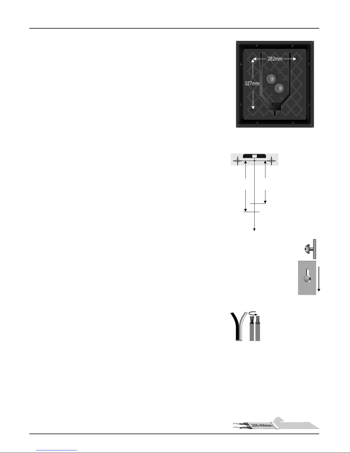
282mm
327mm
Preparing Cables
Determine the location of each panel and if it is to be mounted
portrait or landscape.
Mark out the mounting
centres.
282mm(Portrait)
327mm(Landscape)
Now mark a vertical centre
line down to the floor.
Mark another short line on
the wall at the position
shown. This line is the
upper level for fixing the
cable to the wall.
Drill and fix a No. 8 screw and suitable
wall plug. The screw should protrude
about 5mm from the wall.
Align the keyhole slots over the screws.
Pull gently downwards to secure the
panel. When both panels are correctly
sited, lift them off and lay them to one
side ready for connecting.
Suitable loudspeaker cable is
supplied to connect the pnels to the
subwoofer. This has a tracer on
one cable to aid identification
Divide the cable into two lengths.
cable
.
Prepare each by splitting the twin cores to a depth of
about 25mm . Strip about
length
at each end 7mm of insulation from
each wire. Lightly twist the strands to gather the ends.
Two 2 metre lengths of self adhesive flat cable are supplied to
help you cable the PPS 1 panels. Take each flat cable and mark
on the back a line 200 mm (400mm landscape) from one end.
Carefully score through the backing tape and peel away a short
length of backing tape
To Floor
420mm
Portrait
370mm
Landscape
Connecting the PPS 1 Panels
The PPS 1 panel uses spring terminals located on the rear.
Positive, Red(+) and Negative, Black(-) terminals are clearly
identified.
The flat cables terminate in wire pigtails. Take each flat cable
and connect it to a PPS 1 panel at the end you have prepared.
Connect the pigtail with the Black sleeve to the Black terminal on
the PPS1 panel. Press the lever at the side of the terminal and
insert the cable. Release the lever and the wire is held firm. Now
connect the pigtail with the Red Sleeve to the Red terminal.
Terminals should always grip the bare wire and no strands
should ever touch adjacent terminals.
Hang each panel and cable assembly securely on the wall via the
mounting slots. Hinge the panel slightly away from the wall and
place the cable against the wall with the start of the exposed
adhesive against the marked horizontal line. Ensure that the
pigtail with the BLACK sleeve is to the RIGHT as viewed from the
front.
Run the cable carefully down the wall, peeling off the backing
tape and attaching the cable as you go. Keep the cable centered
on the vertical line.
When the cable is 5mm above the floor covering, cut away the
loose backing strip and run a cloth over the cable to press it
firmly to the wall.
The flat cable is connected to the LP 1 sub bass unit via a length
of speaker cable attached to the flat cable with a twin terminal
block.
Partially unscrew the screws on the terminal
block. Insert a bared end of each pigtail on
the flat cable into each hole at one end of the
block and screw them in place. Now screw in a
prepared speaker cable at the other end.
Make sure that the stripe or rib on the speaker
cable connects to the BLACK pigtail.
The panels are now ready for connection to the sub bass unit.
Connect striped
core to pigtail with
black marker
Lower limit
of adhesive
To Sub-Bass Unit
Wharfedale PPS 1 System User Guide
NXT™ is a trademark of New Transducers Ltd.
AC INPUT
OFF
INPUT
ON
PANEL SPEAKER
+
_
+
_
RIGHT
LEFT
POWER
LEFT
RIGHT
Connections to Panels
Signal Input
Mains Power Input
Power Switch
MIN MAX MIN MAX
INPUT
STEREO
BASS
LEVEL
POWER
MASTER
LEVEL
RIGHT
SPEAKER
PANEL
AC INPUT
OFF
INPUT
ON
PANEL SPEAKER
+
_
+
_
RIGHT
LEFT
POWER
LEFT
RIGHT
LEFT
SPEAKER
PANEL
RIGHT
LEFT
CD PLAYER, ETC
LINE OUTPUTS
LP 1A SUB BASS
TERMINALS
SYSTEM CONNECTIONS
Important Safety Precautions - Please Read Carefully!
Preliminaries
Antenna Grounding: If an outside antenna or cable system is connected to the product, be sure the antenna or
cable system is grounded so as to provide some protection against voltage surges and built-up static charges.
Article 810 of the National Electrical Code, ANSI/NFPA 70, provides information with regard to proper
grounding of the mast and supporting structure, grounding of the lead-in wire to an antenna discharge unit,
size of grounding conductors, location of antenna-discharge unit, connection to grounding electrodes, and
requirements for the grounding electrode. (Refer to diagram)
Power Lines: An outside antenna system should not be located in the vicinity of overhead power lines or other
electric light or power circuits, or where it can fall into such power lines or circuits. When installing an outside
antenna system, extreme care should be taken to keep from touching such power lines or circuits as contact with
them might be fatal.
Read Instructions: All the safety and operating instructions should be read before the product is operated.
Retain Instructions: The safety and operating instructions should be retained for future reference.
Heed Warnings: All warnings on the product and in the operating instructions should be adhered to.
Follow Instructions: All operating and use instructions should be followed.
Cleaning: Unplug this product from the wall outlet before cleaning. Do not use liquid cleaners or aerosol
cleaners. Use a damp cloth for cleaning.
Attachments: Do not use attachments not recommended by the product manufacturer as they may cause
hazards.
Water and Moisture: Do not use this product near water - for example, near a bath tub, wash bowl, kitchen
sink, or laundry tub, in a wet basement; or near a swimming pool; and the like.
Accessories: Do not place this product on an unstable cart, stand, tripod, bracket, or table. The product may fall,
Overloading: Do not overload wall outlets, extension cords, or integral convenience receptacles as this can
causing serious injury to a child or adult, and serious damage to the product. Use only with a cart, stand, tripod,
result in a risk of fire or electric shock.
bracket or table recommended by the manufacturer, or sold with the product. Any mounting of the product should
follow the manufacturer's instructions, and should use a mounting accessory recommended by the manufacturer.
Object and Liquid Entry: Never push objects of any kind into this product through openings as they may touch
dangerous voltage points or short-out parts that could result in a fire or electric shock.
Moving the Product: A product and cart combination should be moved with care. Quick stops, excessive force,
and uneven surfaces may cause the product and cart combination to overturn.
Heat: The product should be situated away from heat sources such as radiators, heat registers, stoves, or other
products (including amplifiers) that produce heat.
Ventilation: Slots and openings in the cabinet are provided for ventilation and to ensure reliable operation of
the product and to protect it from overheating, and these openings must not be blocked or covered. The
Servicing: Do not attempt to service this product yourself as opening or removing covers may expose you to
openings should never be blocked by placing the product on a bed, sofa, rug, or other similar surface. This
dangerous voltage or other hazards. Refer all servicing to qualified service personnel.
product should not be placed in a built-in installation such as a bookcase or rack unless proper ventilation is
Damage Requiring Service: Unplug this product from the wall outlet and refer servicing to qualified service
provided or the manufacturer's instructions have been adhered to.
personnel under the following conditions:
Power Supply Cords: Power supply cords should be routed so that they are not likely to be walked on or pinched
a) When the power supply-cord or plug is damaged
by items placed upon or against them, paying particular attention to cords at plugs, convenience receptacles,
b) If liquid has been spilled, or objects have fallen into the product
and the point where they exit from the product.
c) If the product has been exposed to rain or water.
Power Sources: This product should be operated only from the type of power source indicated on the marking
d) If the product does not operate normally by following the operating instructions. Adjust only those controls that
label. If you are not sure of the type of power supply to your home, consult your product dealer or local power
are covered by the operating instructions as an improper adjustment of other controls may result in damage and
company. For products intended to operate from battery power, or other sources, refer to the operating
will often require extensive work by a qualified technician to restore the product to its normal operation.
instructions.
e) If the product has been dropped or damaged in any way.
Polarisation: This product is equipped with a polarized alternating-current line plug (a plug having one blade
f) When the product exhibits a distinct change in performance - this indicates a need for service.
wider than the other). This plug will fit into the power outlet only one way. This is a safety feature. If you are
Replacement Parts: When replacement parts are required, be sure the service technician has used replacement
unable to insert the plug fully into the outlet, try reversing the plug. If the plug should still fail to fit, contact your
parts specified by the manufacturer or have the same characteristics as the original part. Unauthorised
electrician to replace your obsolete outlet. Do not defeat the safety purpose of the polarized plug.
substitutions may result in fire, electric shock, or other hazards.
Lightning: For added protection for this product during a lightning storm, or when it is left unattended and
Safety Check: Upon completion of any service or repairs to this product, ask the service technician to perform
unused for long periods of time, unplug it from the wall outlet and disconnect the antenna or cable system. This
safety checks to determine that the product is in proper operating condition.
will prevent damage to the product due to lightning and power-line surges.
Example of Antenna Grounding as
per National Electrical Code
Example of Antenna Grounding as
per National Electrical Code
Antenna lead in wireAntenna lead in wire
Grounding Conductors
(NEC Section 810-71)
Grounding Conductors
(NEC Section 810-71)
Ground clampsGround clamps
Electric service
equipment
Electric service
equipment
Power service grounding electrode system
(NEC ART 250, Part H)
Power service grounding electrode system
(NEC ART 250, Part H)
Antenna discharge unit
(NEC Section 810-20)
Antenna discharge unit
(NEC Section 810-20)
Ground clampsGround clamps
The lightning flash with arrowhead symbol, within an equilateral triangle, is intended to alert
the user to the presence of uninsulated dangerous voltage within the product’s enclosure that
may be of sufficient magnitude to constitute a risk of electric shock to persons.
The exclamation point within an equilateral triangle is intended to alert the user to
thepresence of important operating and maintenance (servicing) instructions in the literature
accompanying the appliance.
CAUTION
RISK OF ELECTRIC SHOCK DO NOT OPEN!
!
SOME IMPORTANT DO’S AND DON’TS ESSENTIAL INFORMATION FOR UK USERS
The mains lead on your PPS 1 Active sub bass unit may be supplied with a plug incorporating a
fuse, the value of which is indicated on the pin face of the plug. Should the fuse need to be
replaced, an ASTA or BSI approved BS1362 fuse must be used of the same rating. If the plug is cut
off it must NOT be re-used. Dispose of any such plug safely. There is a danger of electric shock if a
cut-off plug is inserted into a mains socket.
NEVER remove any components and refer all servicing to qualified personnel. This product
The wires in the mains lead are coloured in accordance with the following code:
contains no user serviceable parts.
Green and Yellow - Earth: Blue - Neutral: Brown - Live.
As the colours of the wires in the mains lead may not correspond with the markings identifying the
DO NOT use Active subwoofer unit at extreme high settings of volume and hass output. The
terminals in the replacement mains plug, proceed as follows:
resulting high levels of distortion may damage your loudspeakers.
The wire coloured Blue must be connected to the
DO turn down the main volume control on your system before turning the equipment on or off.
terminal marked with the letter "N" or coloured Black.
The wire coloured Brown must be connected to the
terminal marked with the letter "L" or coloured Red.The
wire coloured Green and Yellow must be connected to
the terminal marked with the letter ‘E’,or coloured
Green, or Green and Yellow, or marked with the Earth
symbol
AVOID trailing cables across open floors where they can be a source of danger.
WARNING: To reduce the risk of fire or electrical shock do not expose the product to rain or
moisture. The product must not be exposed to dripping and splashing and no object filled with
liquids such as a vase of flowers should be placed on the product.
NO naked flame sources, such as candles must be placed on the product.
Before making connections to your sound system make sure all components are switched off.
Always fit the PPS 1 panels according to the instructions and using appropriate fixings. Your dealer will
advise you if needed.
Do NOT connect the PPS 1 panels directly to the loudspeaker outputs of a stereo or Home
Theatre power amplifier or the front speaker outputs of an AV unit. Connections from these
sources should only be via the terminal panel on the LP 1A sub bass unit.
GREEN
&
YELLOW
(EARTH)
BLUE
(NEUTRAL)
(LIVE)
BROWN
FUSE
WARNING
The mains power switch for this appliance is located on the rear panel. The Active Subwoofer must be located in an open area without any obstructions to permit free access to this switch.
Page 3
Specifications
B
R
I
TA
IN
'S
MOS
T
FAM
OUS
L
O
U
D
S
P
E
A
K
E
RS
BR
I
TA
IN'S
MOS
T
FA
M
OUS
L
O
U
D
S
PE
AKE
R
S
Specifications
Page 4
PPS 1
System
Instruction Manual
BRITAIN'S MOST FAMOUS LOUDSPEAKERS
Incorporating
Surface Sound Technology
Page 5
Introduction Compatibility
The Wharfedale PPS 1 system is a unique sub
Your Wharfedale PPS 1 system has been
bass unit and satellite system based on
designed to be compatible with the great majority
revolutionary NXT™ Surface Sound technology.
of hi-fi and audio-visual equipment currently
Now for the first time all listeners in the room can
available. If you have any doubts your dealer will
enjoy spacious, detailed sound, not just the
be happy to offer you advice.
favoured few directly on line with the speakers.
The PPS1 panels employ a protection
Please read the following information before
mechanism that mutes the sound if the power
installing your PPS 1 System. It will help you
input is too great. If the output is muted, turn
install your system safely and correctly .
down the main volume control on the system for
a few seconds to reset the level.
Before making connections to any part of your
Your PPS 1 panels are supplied fitted with
sound system make sure the amplifier and all
lightweight decor pictures fixed to the panel
connected sources are switched off.
surface with low-tack adhesive. If you wish to
When you switch on your system or change
remove or change these pictures, please read
sources, set the volume control to minimum and
the paragraph 'Customising the PPS 1 Panels'
turn up the level gradually.
DO NOT use your amplifier at full volume.
Mounting the Panels
The position of the Volume Control is NOT a
The PPS 1 panels are designed to wall mount.
reliable guide as to the maximum volume level or
A conventional loudspeaker needs to be
capabilities of your sound system. Playing the
focussed on the listening position and placed at
system with extreme high settings of volume and
an equal distance from the listener. Although this
tone controls will result in distorted sound and
conventional placement is still the preferred
may damage the amplifier and loudspeakers.
position, the position of the panels is not critical,
DO NOT connect loudspeaker terminals to the
except that you should not position the panels
mains supply.
immediately next to each other. The panels can
Ensure that all loudspeakers in the system are
be placed at different heights to each other and
correctly wired and are in phase.
at different distances from the listening seat.
DO NOT subject your loudspeakers to excessive
Each PPS 1 panel should be placed to the front
cold, heat, humidity or sunlight.
or side of the listening position. Place the panels
behind the listening position only if you are using
WARNING: To reduce the risk of fire or electrical
them as the rear speakers in a surround system.
shock do not expose this product to rain or
moisture. The product must not be exposed to
Fixing the Panels to the W all
dripping and splashing and no object filled with
Three keyhole slots are located on the back of
liquids such as a vase of flowers should be
each panel so that the panel may be wall
placed on the sub bass unit.
mounted in either portrait or landscape mode.
No naked flame sources - such as candles - must
The PPS 1 is not supplied with screws or fixings.
be placed on the sub bass unit.
Ensure correct selection of screws (they must
DO NOT place heavy objects on top of the sub
be round head, No 8) and fixings appropriate to
bass unit cabinet.
the structure and material they are to be applied
NEVER let anyone, push anything into holes,
to. Seek qualified assistance if necessary.
slots or any other opening in the case.
The mounting screws must be securely fastened
Always fit the PPS 1 panels according to the
into the wall or base structure. The entire
instructions and using appropriate fixings. Your
assembly should be capable of taking the weight
dealer will advise you if needed.
of the PPS 1 panels together with any pulling
Do NOT connect the PPS 1 panels directly to the
force to which they might be subjected.
loudspeaker outputs of a stereo power amplifier
or the front speaker outputs of an AV unit.
Connections to these outputs should only be via
the terminal panel on the LP 1 sub bass unit.
DO NOT attempt to dismantle the units. There
are no user serviceable parts inside and you will
invalidate the warranty.
Site the LP 1 sub bass unit at least 0.5m from
TV sets and magnetic storage media. The PPS1
panels may be safely used close to a TV set.
Unpacking
Unpack your system with care. Be careful not to
damage the panels and sub bass unit cabinet
when removing the polythene sleeves. Check
each speaker and in the event of any transit
damage, immediately contact your Wharfedale
dealer. Retain the packaging for future transit.
Positioning the Sub-Bass Unit
Although the LP 1 sub bass unit may be placed
almost anywhere in the room, even behind the
sofa or the TV set, we recommend that it be
placed in front of and as central to the listening
position as possible. The sub bass unit should
not be operated within 450mm of a television set
as the drive unit magnet may distort the picture.
We suggest you position the LP 1 sub bass unit
about 20cm (8 inches) from the wall. Placing it
close to the wall will enhance the bass; placing it
across the corner of the room will increase the
bass further, possibly at the expense of clarity .
The bass ports are essential to the functioning of
the sub bass unit and should not be obstructed
by placing the unit against soft furnishings. Do
not place the sub bass unit on an unsound floor
or close to surfaces or objects that may rattle.
Mounting the Panels
Preparing Cables
Determine the location of each panel and if
it is to be mounted portrait or landscape
Mark out the
mounting centres
282mm(Portrait)
327mm(Landscape)
Now mark a vertical
centre guide line
down to the floor.
Mark another short
line on the wall at the
position shown.
This line is the upper
level for fixing the
cable to the wall.
Drill and fix a No. 8 screw and
suitable wall plug. The screw
should protrude about 5mm
from the wall.
Align the keyhole slots over the
screws. Pull gently downwards
to secure the panel.
When both panels are correctly
sited, lift them off and lay them to
one side ready for connecting.
30 metres of loudspeaker
cable is supplied to connect
the PPS 1 to the amplifier. This
has a tracer on one
cable to aid identification
cable
.
Divide the cable into four lengths.
length
at each end 7mm of
insulation from each wire. Lightly twist the
strands to gather the ends.
Two 2 metre lengths of self adhesive flat cable
are supplied to help you cable the PPS 1 panels.
T ake each flat cable and mark on the back a line
200 mm (400mm landscape) from one end.
Carefully score through the backing tape and
peel away a short length of backing tape
Prepare each
by splitting the twin cores to a depth of
about 25mm . Strip about
To Floor
420mm
Portrait
370mm
Landscape
Wharfedale PPS 1 System User Guide
NXT™ is a trademark of New Transducers Ltd.
Page 6
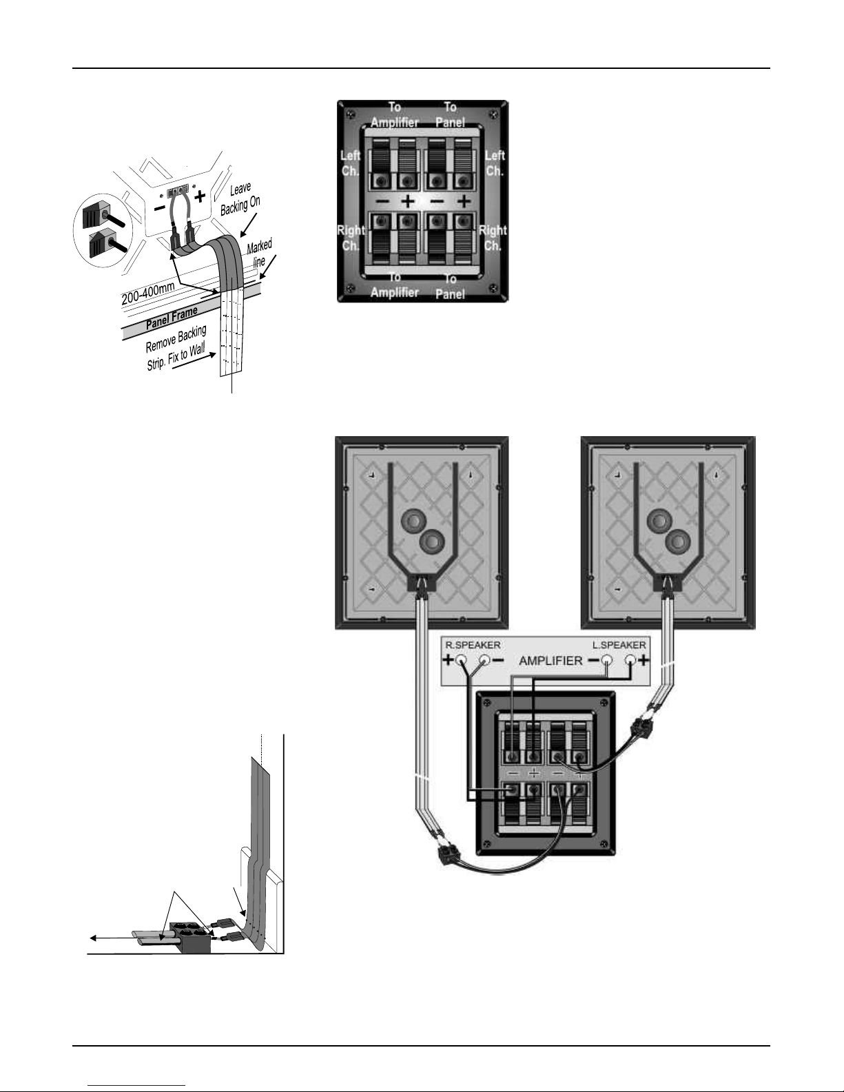
Connecting the PPS 1 System Panel Connections
Connect the speaker cable attached to the Left
PPS 1 panel to the Left panel connection on the
LP 1 sub bass unit. Connect the wire with the
marker stripe to the Negative (-) Black terminal
and the plain wire to the Positive (+) Red
terminal. Repeat this procedure to connect the
Right panel to the sub bass unit.
Note: The flat cable is supplied as an option. If
you prefer you can connect the panels using the
supplied speaker cable or a suitable a lternative.
Connecting the LP 1 Sub Bass
Using a prepared speaker cable, connect the
Left speaker terminals on the amplifier to the Left
speaker terminals on the sub bass unit . Connect
the Positive, Red (+) speaker terminal on the
The LP 1 sub bass connector panel is the heart
amplifier to the Positive, Red (+) terminal on the
of the PPS 1 system. The Positive, Red(+) and
sub bass unit. Connect the Negative, Black (-)
Negative, Black(-) terminals are clearly
speaker terminal on the amplifier to the
identified.
Negative, Black (-) terminal on the sub bass unit.
Connect the Right speaker terminals on the
The twin terminal pairs on the left connect to the
amplifier to the Right speaker terminals on the
amplifier and the twin terminal pairs on the left
sub bass unit using the above method.
connect to the panels.
Connecting the PPS 1 Panels
The PPS 1 panel uses spring terminals located
on the rear. Positive, Red(+) and Negative,
Black(-) terminals are clearly identified.
The flat cables terminate in wire pigtails. Take
each flat cable and connect it to a PPS 1 panel at
the end you have prepared. Connect the pigtail
with the Black sleeve to the Black terminal on the
PPS1 panel. Press the lever at the side of the
terminal and insert the cable. Release the lever
and the wire is held firm. Now connect the pigtail
with the Red Sleeve to the Red terminal.
Terminals should always grip the bare wire and
no strands should ever touch adjacent terminals.
Hang each panel and cable assembly securely
on the wall via the mounting slots. Hinge the
panel slightly away from the wall and place the
cable against the wall with the start of the
exposed adhesive against the marked horizontal
line. Ensure that the pigtail with the BLACK
sleeve is to the RIGHT as viewed from the front.
Run the cable carefully down the wall, peeling off
the backing tape and attaching the cable as you
go. Keep the cable centered on the vertical line.
When the cable is 5mm above the floor covering,
cut away the loose backing strip and run a cloth
over the cable to press it firmly to the wall.
The flat cable is connected to the
LP 1 sub bass unit via a length of
speaker cable attached to the flat
cable with a twin terminal block.
Partially unscrew the screws on the
terminal block. Insert a bared end of
each pigtail on the flat cable into each hole at one
end of the block and screw them in place. Now
screw in a prepared speaker cable at the other
end. Make sure that the stripe or rib on the
speaker cable connects to the BLACK pigtail.
Connect striped
core to pigtail with
black marker
Lower limit
of adhesive
To Sub-Bass Unit
diagram carefully and ensure that all the
Home Theatre
connections are correctly and securely made. In
The PPS 1 Panels may be purchased as a pair
particular, the colour coding on the loudspeaker
independently of the sub bass unit and are ideal
connections must be strictly observed.
for the rear channels of a home theatre system,
NOTE: Do NOT connect any component in the
where their dispersion pattern provides a wide,
PPS 1 system to any subwoofer output on your
diffuse sound field.
AV amplifier .
A wide range of Wharfedale centre loudspeakers
PPS 1 panels must be connected to the Front
is available - see your dealer for details.
loudspeaker outputs only via the LP 1 sub bass
Connections for a Home Theatre system are
unit. They may, however, be connected directly
shown on the next page - please follow the
to the Rear Channel outputs.
LP 1 SUB BASS
TERMINALS
LEFT
SPEAKER
PANEL
RIGHT
SPEAKER
PANEL
Page 7
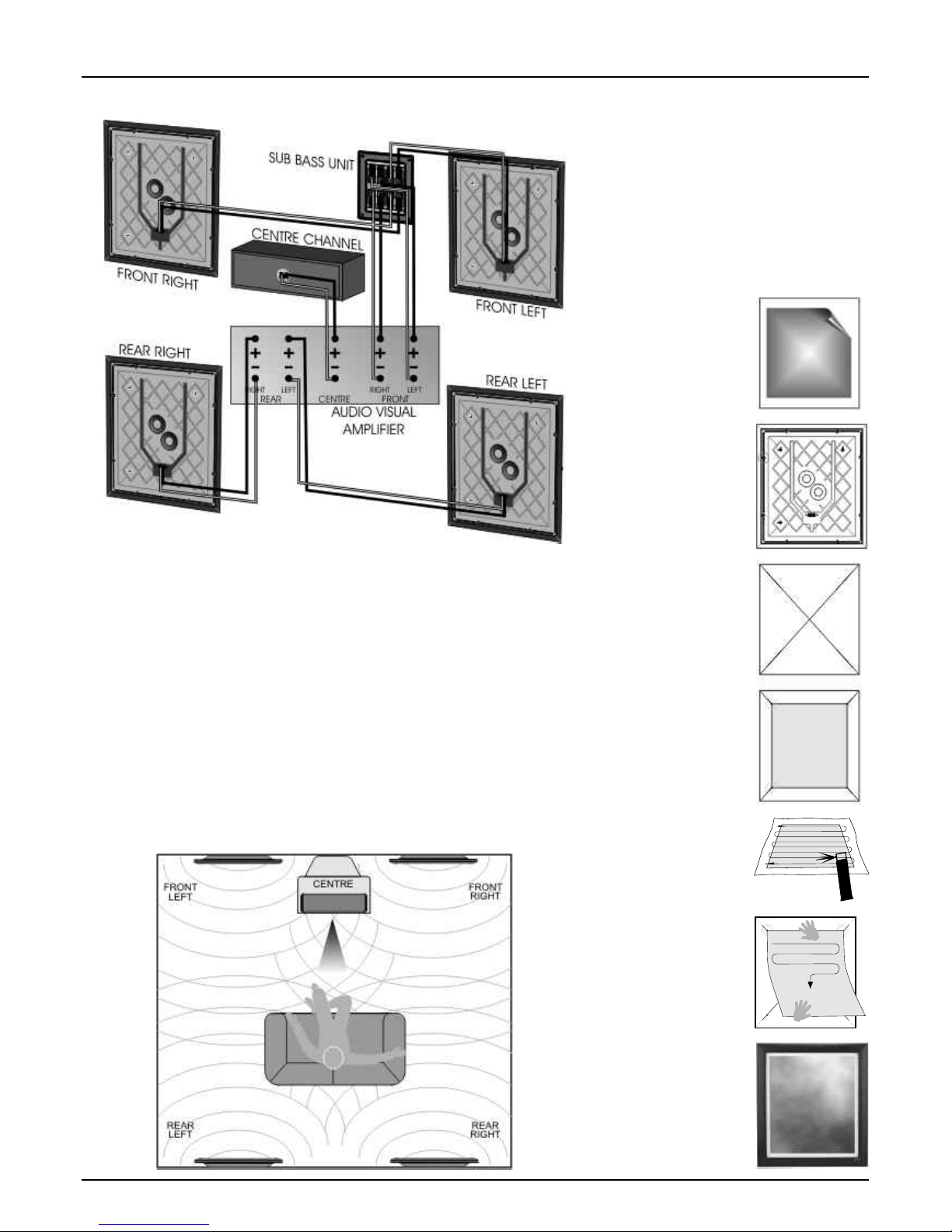
Home Theatre Connections
specify the size of speakers in the various
Home Theatre Environment
channels. These are usually ‘Large’ or ‘Small'.
Although the PPS 1 panels may be placed
The Rear and Centre channels should be set
almost anywhere in the room, it is good practice
to 'Small' as they have no deep bass capability.
to site them conventionally if possible.
Set the Front Channel to 'Large'. All the system
The front channel panels should be placed on
bass is now routed through the LP 1 sub bass
either side of the television screen, 2 to 3 metres
unit. The subwoofer channel on the processor
apart. The Centre speaker should be placed
should be set to ' No' or 'Off'.
central to the listening position and close to the
If your AV processor has an LFE control, use
TV screen. Ideally, the front and centre channel
care as the LFE channel may contain heavy low
speakers should be operated with their centres
frequencies which can overload a domestic unit.
at the same height though this is not essential.
If, during a programme, you hear popping or
We recommend placing the rear panels behind
thumping noises coming from the LP 1 sub bass
the listener and above the listening position. Site
unit, immediately turn the A V Processor's volume
the LP 1 sub bass unit as previously described.
level down and then back off the LFE level.
Many digital AV Processors require you to
Customising the PPS 1 Panels
The PPS 1 Panel can be customised with your
choice of graphics. For a small charge most high
street picture specialists will be happy to apply
your image to the PPS 1. If you wish to do this
yourself, carefully follow the instructions below.
The material on which the image is applied
should be lightweight-less than 300gsm. Canvas
or painted surfaces are not suitable, nor should
the print be glazed. There must be white space
all round the print. We suggest a maximum
picture size of 360mm x 420mm.
Lay a straight edge
diagonally across the
corners of the panel.
Using a soft blunt 2B
pencil or whiteboard
marker gently mark four
short lines as shown.
These marks can be
removed with a rubber
after the print is fixed.
First remove the
existing print.
Carefully lift one corner
with a fingernail or
wooden spatula and
slowly peel off the print.
To aid picture mounting
the frame may be
removed.
Carefully remove the
eight screws in the
moulded back cover
and put safely to one
side. Lift off the frame.
Lay the print face down
on some newspaper.
Using a suitable spray
mount adhesive, lightly
spray the back of the
print as indicated.
Allow to dry for 2-3
minutes.
Apply the print and
position it along the top
edge only. Gently rub
from side to side
moving down the print
whilst lowering it on to
the panel. Smooth out
any creases as you go.
Place the print on the
panel. When the
corners touch all four
lines, the print is
centred. Mark the
corner positions.
Erase all the guide
lines. Secure the
picture frame back into
place using the original
eight screws removed
earlier.
Page 8

hours or so play your system at reasonable volume levels. After running in,
Phase
you will notice a sonic improvement, especially in the sub bass unit.
If the sound lacks definition or the bass is indistinct, the speakers could be
incorrectly wired (out of phase). If this is the case please check the wiring
to the loudspeakers carefully. This is particularly important if you have a
Home Theatre system.
Ancillary Equipment
Y our Wharfedale speakers are compatible with the great majority of audiovisual and high fidelity equipment currently available - but a loudspeaker is
only as good as the signal it gets. Your amplifier should have ample
reserves of power - a low powered amplifier could run out of steam quite
easily and the resulting distortion is unpleasant to listen to and could
Care and Maintenance
damage your speakers. A larger amplifier will usually sound better and
Very little maintenance is required. The Picture Panel frame and the
enhance the reliability and performance of your loudspeakers.
surface of the panel can be occasionally wiped clean with a soft damp (not
Running In
wet) cloth. Do not use detergents or solvents. Take care to use an
appropriate method if you have applied your own picture or painting.
Like all mechanical systems, loudspeakers to be 'run in'. For the first 50
Connecting Wires
Avoid trailing cables across open floor spaces where they can be a source
of danger. Route cables safely under carpets or along room boundaries.
When mounting a panel on a wall the connecting cables may be
unacceptably obvious. Whilst the flat cable would normally be routed from
the panel to the floor, it may be less obtrusive to route cables from the panel
to the ceiling and then within or immediately underneath the ceiling (or
coving). The cable may then return to floor level at a convenient room corner.
Getting the Best From Your Loudspeakers
Television picture is distorted or there is colour
distortion
The LP 1 sub bass unit is too close to the TV. (Switch off the system and TV. Move the sub
bass away. Leave 20 mins. Switch on again)
Excessive bass distortion at low volume levels
Processor Subwoofer level set too high (where AV Processor is used)
Processor LFE level set too high (where AV Processor is used)
Excessive or distorted bass at high volume levels
Pops or thumps from the sub bass unit
System level set too high, bass control set too high
Sub bass unit too close to room corners
Processor LFE or Subwoofer level set too high (where AV Processor is used)
Sound consists of just bass frequencies
No treble from one channel
Check connections and cables from sub bass to PPS 1 panels
The built in protection device on one or both PPS 1 panels has operated. Turn down the
volume control on your audio system until full output is resumed.
Indistinct sound, poor localisation of effects
One or more loudspeakers is out of phase
(See the relevant pages of this manual for the correct connection procedure)
Distorted or rattling sounds at high volume levels
System level set too high
Objects placed on sub bass unit
Objects too close to sub bass unit
Sound lacks bass content
Bass reproduction muddy or indistinct
Check the connections between the sub bass unit and the amplifier
No sound at all
Check that your hi-fi system is turned on and working ok.
Check all connections and cables. Ensure there are no short circuits across terminals.
Check that cables are not broken along their length.
Symptom
Possible Cause
If your sound system appears not to be working as well as you expect, the Please read this manual together with all the manuals concerning the rest
following notes may be of some help. of your system. If, having attempted to resolve the problem, the trouble
still persists, consult your dealer for assistance.
Before investigating the cause of a problem, always switch off the system
at the mains. Do NOT try to remove any covers on the products or attempt to dismantle
them in any way. There are no user serviceable parts inside and you will
If you are using a Home Theatre system remember that such systems
invalidate any warranty.
can be quite complex and there is often a variety of factors involved.
Troubleshooting Guide
A wide range of AV and audio topics can be found at the Wharfedale web site. www.wharfedale.co.uk
Page 9

Specifications
Nominal Impedance
Power Handling
(Programme)
Sensitivity (1W@1M)
Freq. Response (-6dB)
System Crossover Freq.
System LF Response (Fb)
Dimensions Overall
H x W x D mm
H x W x D inches
8 Ohms
70 Watts
87dB
(DML connection)
80Hz - 20KHz
160Hz
35Hz
555 x 500 x 27
21.8 x 19.7 x 1.1
PPS 1 Panel
Wharfedale loudspeakers are compatible with 4 and 8 Ohm amplifiers
Service & Information
The name WHARFEDALE' is a registered trademark of Wharfedale International Limited.
Wharfedale has a policy of continuous product development and reserves the right to change specification without notice.
Wharfedale is a member of the International Audio Group.
1932
In 1932, when Gilbert Briggs founded the Wharfedale Wireless
Works, his company was at the leading edge of an exciting new
technology which was dedicated to bringing the pleasure of music
and entertainment to a wide range of people. As the technology
advanced Wharfedale gave many music lovers their first taste of
High Fidelity, mounting a series of live sound demonstrations which
excited the audio world and heralded the era of the modern hi-fi
loudspeaker.
Today Wharfedale still takes the same uncompromising approach to
the design and manufacture of every loudspeaker system, using high
quality components and state-of-the-art testing to ensure consistently
high performance. And that means that you can continue to count on
the quality of all Wharfedale products.
Loudspeaker Manufacturers since 1932
Product service enquiries should, in the first instance,
be referred to the supplying dealer. In cases of
difficulty or for other product enquiries please contact
the appointed Wharfedale distributor for the country.
UK (and information about all other territories)
8 Ohms
70 Watts
87dB
40Hz - 170Hz
235 x 460 x 210
9.25 x 18.1 x 8.26
LP1 Sub-Bass
IAG America, Inc.
180 Kerry Place
Norwood
MA 02062
USA
Tel: +1 781 440 0888
Fax: +1 781 440 0333
UNITED STATES OF AMERICA
Wharfedale International Ltd.
IAG House, Sovereign Court,
Ermine Business Park, Huntingdon,
Cambs PE29 6XU, England.
Tel: +44 (0)1480 447700
Fax: +44 (0)1480 431767
www.wharfedale.co.uk
Drive Units
2x25mm Exciter 170mm Bass
 Loading...