

Page 1
EZ-m
OWNER’S MANUAL
mini-mixer 16x2
Page 2

Table of Contents
Page
1 Introduction / Features / Back Panel diagram
portant Safety & Warranty Information
2 Im
3 Detailed Features of the EZ-m 10x2 – Mono M
4 Mono Mic/Line Channel
- Low Impedance (Low Z) MIC Input
- LINE IN
- GAIN Control
- CLIP LED
5 EQ Section
nel PAN and LEVEL
6 Stereo Channel Inputs
- BALANCE & LEVEL
7 MASTER Section
- POWER LED & Signa
8 - 2TK IN
- 2TK OUT
- MAIN O
- Mono Channel
- Mono Chan
l Metering
UT ¼” L/R Outputs
ic/Line Input Channel
- PHONES
9 - POWER Switch On/Off
- AC Power
- CONNECTION WIRING
- MIC Inputs
- LINE Inputs
- MAIN MIX O
- Stereo 2 Trac
- Headphone Outputs
10 SPECIFICATIONS
11 BLOCK DIAGRAM
Back Cover - Contact In
Cable Connector
utputs
k Inputs and Outputs (2TK IN / 2TK OUT)
(PHONES)
formation
DETAILS
Page 3
Introduction
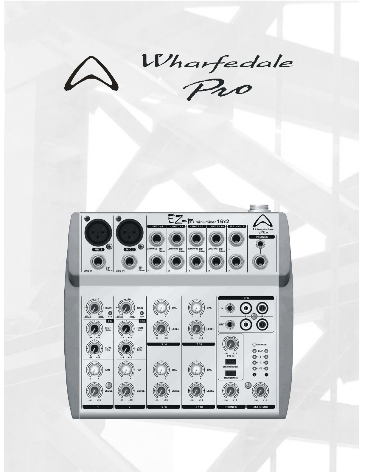
Thank you for purchasing a Wharfedale Pro EZ-m mini-mixer. The Wharfedale Pro EZ-m Series
mixers are designed for ease of use and quality audio performance. Please read this manual
completely to ensure proper understanding of the features and operation of your mixer.
FEATURES
EZ-m 16x2
- 2 Mono balanced / unbalanced mic / line input channels with 2 Band equalization.
- Variable input GAIN controls on mic/line channels
- CLIP LED’s on mic/line channels
- 4 Stereo channels with balanced / unbalanced ¼” Tip-Ring Sleeve (TRS) jacks.
- “2 Track” stereo inputs and outputs with 1/8” stereo and dual RCA jacks
- “2 Track” assignable (2TK TO MAINS, 2TK TO PHONES) switches with level control.
- Separate MAIN MIX, and PHONES outputs with level controls
- 4 segment, stereo bar-graph LED meters
- Convenient 1/8” stereo jacks for 2TK IN, 2TK OUT and PHONES
1
Page 4

Important Safety & Warranty Information
1
. Power Supply
This EZ-m Series mini-mix
supply provided with your mixer. Use of any other power supply could cause damage to the mixe
and other equipment. Connect the power supply to the mixer BEFORE connecting it to the power
source outlet. Be sure to allow for free airflow around the mixer, as it may become warm during
long periods of operation. The mixer is shipped with the correct power supply for the co untry in
which it is to be used. This can be verified by checking the label on the power supply.
er is supplied with an external power supply unit. Use only the power
. Packing
2
The exterior and
If any shipping damage has occurred, consult your dealer and the shipping provider.
interior packaging has been designed protect the mixer during transit.
. Safety
3
Avoid exposing
operate the mixer away from locations where it is likely to be exposed to these conditions.
Also, avoid placing your EZ-m Series mixer in locations which may be subject to excessive
vibration/physical shocks that could cause mechanical damage to the mixer.
your EZ-m Series mixer to excessive heat, humidity and dust. Store and
r
W
ARNING: REFER ALL MAINTENANCE, REPAIRS AND MODIFICATIONS TO QUALIFIED
SERVICE PERSONNEL! THIS PRODUCT CONTAINS NO USER-SERVICEABLE PARTS!
For the protection of the mixer and other audio equipment, always turn off the power on the m
and other system components before connecting or disconnecting audio cables. Be aware that
excessive volume levels are possible from the output of this mixer. Protect your hearing
accordingly.
. WARRANTY
4
The EZ-m Series mixers
for a period of one year from the date of purchase. This warranty is non-transferable and applies
only to the original purchaser. If any warranty related issues occur, contact your dealer. Proof of
purchase may be required.
are covered by a limited warranty, against any defects in workmanship
ixer
2
Page 5
DETAILED FEATURES OF THE EZ-m 16x2
Mono Mic / Line Input Channel
3
Page 6

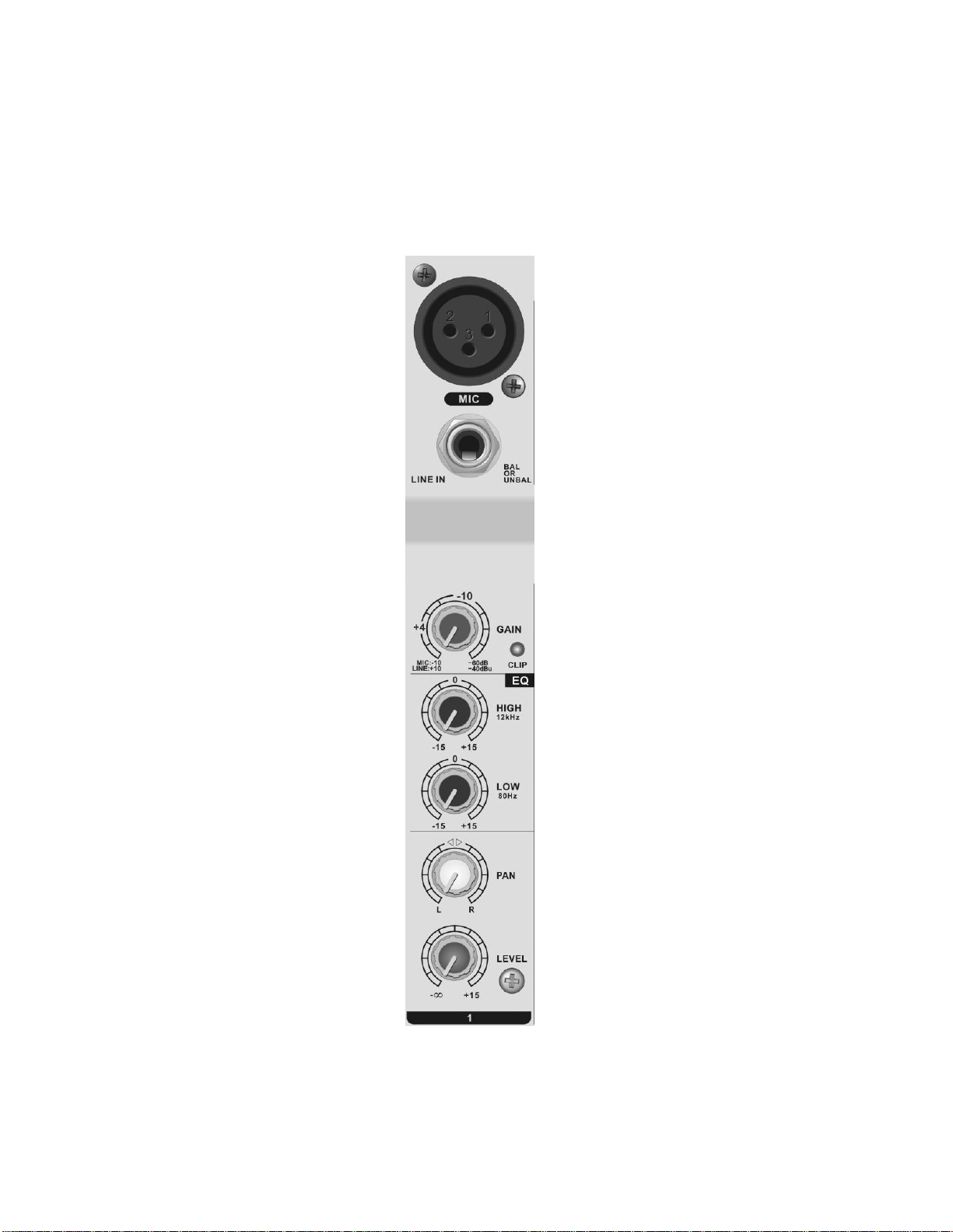
Low Impedance (Low Z) MIC Input
1
he low noise, high headroom “Low Z” MIC inputs are
T
for use with balanced, low impedance dynamic micro
NOTE:
Condenser microphones will not work on this
1
phones.
mixer.
LINE IN
2
T
hese ¼” Tip, Ring, Sleeve (TRS) jacks are designed
to be onnected w
c ith (-10 to +4dBu) balanced or unbalanced
line level sources.
GAIN Control
3
order to achieve the best signal to noise ratio and
In
adequ te dynamic range,
a the input preamp level of the
Mic/Line
mono channel. Set the GAIN control by watching the LE
graph meters—above the MAIN MIX level control in the
Master section of the mixer—while the signal source for that
channel is active (whether it be a microphone or an instrum
connected to the LINE IN of the channel). The ideal level is
between 0dB and +6dB on the bar graph meters.
If the CLIP LED on the channel lights up consistently, the
GAIN control is set too high. It is acceptable for the CLIP
LED to flash periodically especially with loud instruments li
drums or during peak sound levels during loud portions of a
performance.
4
The C IP LEDs (on chan
signal is driven too high. This indicates that the signal is
channel is adjusted with a GAIN control on each
D bar-
ent
ke
CLIP LED
L nel 1) will light up when the input
3
2
4
overloading the preamp and causing distortion.
4
Page 7

EQ Section
5
Channels 1 and 2 each feature a two
band Equalization (”EQ”) section. Each band is
chosen from the prime frequencies for most
musical applications, and allows up to 15
decibels of boost (increase) or cut (decrease) of
the signal in the tone range for which it controls.
In
the center-detent position (0), the equalizer is
bypasse
the tonal characteristics of the signal. The HIG
E
Q control is centered at 12kHz and the LOW
E
Q control is centered at 80Hz.
d (flat)and the control has no effect on
H
Pan and Level
5
6
Pan Control: On Channels 1 & 2,
6
the PAN control adjusts the left/right
balance of the mono signal being sent
to the left and right MAIN MIX outputs.
The Channel 1 LEVEL Control
7
The Channel 1 LEVEL kn
ontrol of the level of the signal that is being
c
s
ent to the MAIN MIX master volume control.
Adjust ea
b
est “mix” ,or balance of signals, from each
in
put.
ch channel level control to acquire the
ob allows for
5
7
Page 8

Stereo Channe
E s on the
ach of the stereo channel EZ-m 16x2
(3/4, 5/6, 7/8, 9/10) fe
with ¼” Tip/Ring/Sleeve
b
alanced and unbalanced left and right input
ignals. These inputs can accommodate both
s
o and mono inputs. When using a mono
stere
ource, connect the cable to the LEFT (MONO)
s
in
put only. Stereo Channels 3 /4, 5/6, 7/8, and
/10 have stereo Inputs with left and right ¼”
9
T
ip/Ring/Sleeve (TRS) input jacks.
L
EFT (MONO) input: When only one plug is
in
serted into the LEFT jack, the channel
o
perates as a mono channel.
l Inputs
ature two line level inputs
(TRS) jacks for both
BALANCE and LEVEL
BALANCE
8
On a stereo chann
Cont
rol
el, with a stereo input
c
onnected, turning the BALANCE control to the
le right input’s signal level to
ft will cause
d
ecrease. Turning the BALANCE control fully
ri
ght on a stereo channel will cause the left
input’s signal level to decrease. If a mono input
is connected to a stereo channel, the BALANCE
control will function as a PAN contr
adjusting the left/right balance of the mono
signal being sent to the left and right MAIN MIX
outputs.
Stereo Channel Level Control
9
The stereo channel level control knob
allows for volume control of both the left and
right signals being sent to the MAIN MIX maste
volume control. If a mono input is connected t
a stereo channel, the channel functi
mono channel.
ol by
r
o
ons like a
8
9
6
Page 9

Master Section
he master section on the right side of the mixer
T
c
ontrols the final gain stage of the mixed signals
fr
om the input channels. The MAIN MIX control
allows for the adjustment of the overall output
level of the EZ-m m
ixer.
POWER LED & Signal Metering
10
POWER LED
This amber LED lights indicating power is on for
the mixer.
Level Meters
11
The signal level of the MAIN MIX
is displayed o
m
eters. Levels shown are -20, 0, 6 and CLIP.
n the 4 segment LED bar-graph
output
7
10
11
Page 10

2TK IN
12
This section consists of two sets of three
input jacks. The top row of jacks are the “2TK
IN” jacks which are a 1/8” stereo jack and a left
and right RCA jack. These inputs allow for the
introdu
mixer. This
volume co
as well as the
1/8” 2T
RCA 2T
three output jacks. These are the bottom row of
jacks in the “2TK OUT” section featuring a 1/8”
stereo jack, and left and right RCA jacks. These
outputs allow for the routing of MAIN MIX stereo
signal out of the mixer. This signal level is
controlled by the MAIN MIX volume control.
When the 1/8” 2TK OUT jack is used, it takes
ction of an external stereo signal to the
signal is controlled by the 2TK IN
ntrol and the 2TK TO PHONES switch
2TK TO MAINS switch. When the
K IN jack is used, it takes priority over the
K IN jacks.
2TK OUT
13
This section also consists of two sets of
12
13
priority over the RCA 2TK OUT jacks.
MAIN OUT ¼” L/R Outputs
14
eft and Right balanced, TRS (Tip, Ring,
L
S ¼” ou
leeve) tput jacks for connection to
a
mplifier inputs or recording device inputs.
Phon
15
This is a standard ¼” Tip-Ring
(TRS) amplified stereo headph
A parallel connection to a convenient 1/8” mini
s
tereo headphone jack is also included, allowing
fo
r portable headphones and ear buds. Volume
is
set with the PHONES level control. Be aware
th
at very high volume levels are possible from
th
is output. Make sure the level is set all the way
d
own before connecting headphones.
es
-Sleeve
one output jack.
8
14
15
Page 11

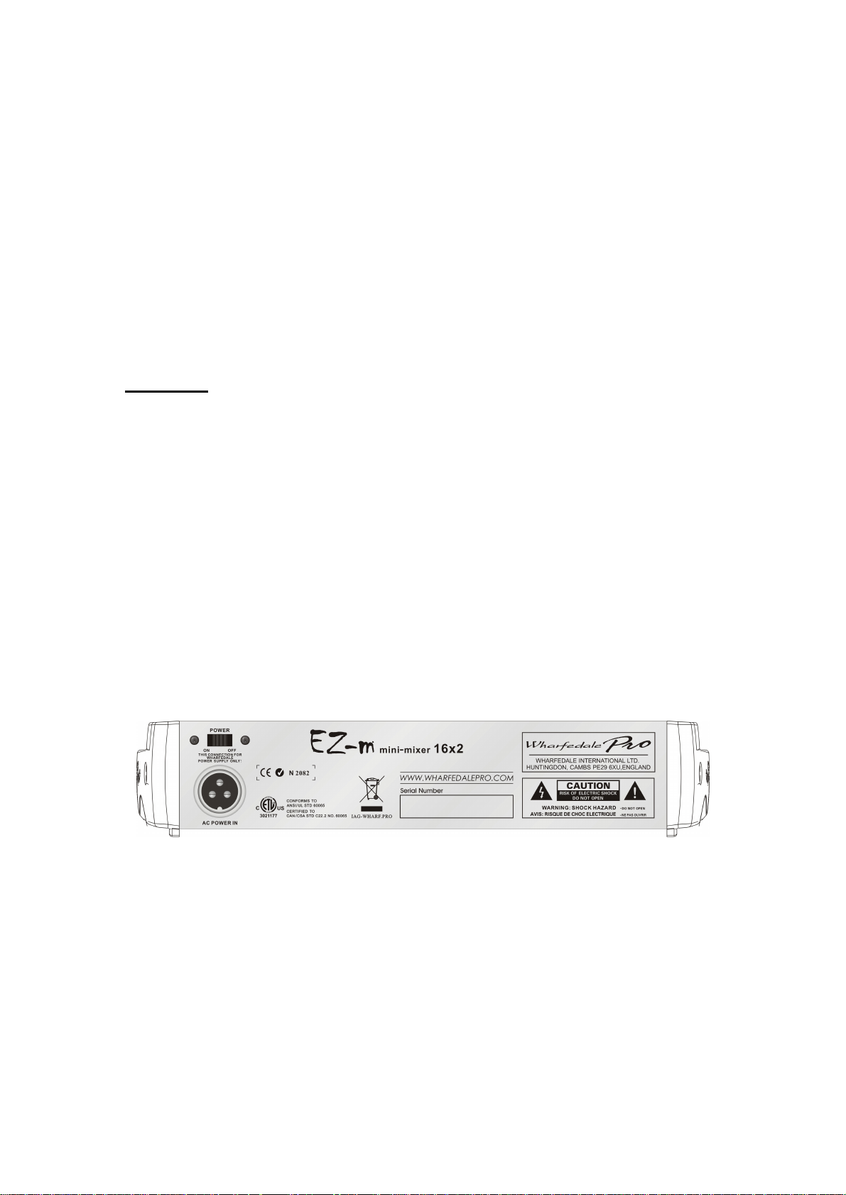
16
P
OWER Switch – On/Off
This slide switch turns the unit on and off.
16
Always power down the EZ-m when it is not in u
Be sure to turn off all system amplifiers or powere
speakers before turning off the mixer.
17
AC Power Cable Connector
The included power adaptor connects here. Use only the po
supplied with the mixer
se.
d
wer adaptor
ONNECTION WIRING DETAILS
C
MIC Inputs (Microp one)
he microphone (MIC) jack is a female XLR connector wired balanced with:
T
in 1 = ground, Pin 2 = hot (+) and Pin 3 = cold (-).
P
h
Line Inputs
he mono and stereo LINE inputs are wired with ¼” Tip Ring Sleeve jacks, wired balanced with:
T
¼” - Tip = hot (+), Ring =
cold (-), Sleeve = ground, although standard ¼” unbalanced phone plugs
17
c
an also be used, wired Tip = hot (+), Sleeve = groun
d.
MAIN MIX Outputs
MAIN MIX with ¼” Tip Ring Sleeve jacks, wired balanced with:
he outputs are wired T
¼” - Tip = hot (+), Ring = cold (-), Sleeve = ground, although standard ¼” unbalanced ph plugs
can also
Stere
The Stereo 2 Track Inputs and Outputs (2T o plugs and 1/8”
stereo jacks. RCA jacks are wired unbalanced as:
Tip = hot (+), Sleeve = ground (-).
1/8” stereo jacks are wired as:
Tip =
Hea phone Outputs (PHONES)
The Headphone output is wired with both 1/8” and ¼” Tip Ring Sleeve jac
¼” - Tip = Left, Ring = Right, Sleeve =
be used wired, Tip = hot (+), Sleeve = ground.
o 2 Track Inputs and Outputs (2TKIN / 2TK OUT)
K IN / 2TK OUT) are wired with RCA phon
Left, Ring = Right, Sleeve = Ground.
d
ks which are wired as follows:
ground
one
9
Page 12

SPE
CIFICATIONS
EZ-m mini-mixer 16X2 Specifications
Maximum Output Level
(1%T.H.D. @ 1kHz)
THD+N% <0.01% @ +15dBu
Frequency Response 20Hz-20kHz +0/-1dB
Hum and Noise
Maximum Input Levels
Mono Input Channel
Gain
Input Channel EQ
Level Meter 4-Segment LEDx2 (output of '+4dBu = MAIN L/R
Clip Indicator Turns on approx +16dBu
AC Power options AC100V/120V/230V/240V, 50 Hz/60Hz
Dimensions 311mm x 77mm x2 26mm / 12.24" x 3.03" x 3.16"
Weight 1.81kg / 3.98 lbs
Details, features and specifications subject to change without notice.
+22dBu over 130mw (headphone) @ 32 ohms
-127dB Mic Pre Equivalent Input Noise
'-90dBu Residual Noise
Mic In: '+10dBu
Line In: '+20dBu
2TK In: '+20dBu
50dB Variable (-60~-10dB) (-40dB~+10dB)
High (+/- 15dB) 12kHz Shelving
Low (+/_15dB) 80Hz Sh
elving
10
Page 13

BLOCK DIAGRAM
11
Page 14

IAG Professional reserves the right to a improve specifications without notice.
Wharfedale International LTD.
IAG HOUSE
Sovereign Court, Ermine Business Park,
Huntingdon, Cambs,
PE29 6XU, England
www.wharfe alepro.com
d
lter or
All rights reserved © harfedale Pro
Wharfedale Pro is a member o onal Audio Group
2007 W
f the Internati
 Loading...