

Wharfedale Pro Diamond 9.4, Diamond 9.CC, Diamond 9.5, Diamond 9.6, Diamond 9.CS Instruction Manual
...
The name ‘WHARFEDALE' is a registered trademark of Wharfedale
International Ltd.
Wharfedale has a policy of continuous product development and reserves
the right to change specification without notice.
Wharfedale is a member of the International Audio Group.
USA
IAG America, Inc.
15 Walpole Park
South
Walpole
MA 02081
CANADA
Korbon Trading Ltd
6800 Kitimat Road
Units 19-20
Mississauga
Ontario
Tel: +1 905 567 1920
UK
Wharfedale International Ltd.
IAG House, Sovereign Court,
Ermine Business Park,
Huntingdon,
Cambs PE29 6XU,
England.
Tel:+44 (0)1480 447700
Fax: +44 (0)1480 43176
AUTHORISED SERVICE CENTRES
For information on other authorised service centres worldwide contact
Wharfedale International in the U.K.
A worldwide distributor list is available on the Wharfedale website:
www.wharfedale.co.uk
COMPLIANCE
This Wharfedale product complies with the relevant clauses enshrined in the following standards and directives in force at the time of the
introduction of the product.
! EU Directives: 89/336/EC, 72/23/EEC: Safety: EN60065 (CB Scheme): Emissions: EN55013, EN61000 Immunity: EN55020:2002.
! USA: UL 6500:2002. Approved under the verification provision of FCC Part 15 as a Class B Digital Device.
! CANADA: CAN/CSA-E60065-00
Television picture colour is distorted Subwoofer too close to TV. (Switch off system and TV. Move units away. Leave 15 mins. Switch on)
Excessive bass distortion at low volumes
Subwoofer level set too high; LFE level set too high; Subwoofer incorrectly wired
Excessive or distorted bass at high levels
System level set too high; Bass control set too high; Speakers too close to room corners
Popping or thumping from the subwoofer
System level set high; Subwoofer level set too high; LFE level set too high
Indistinct sound; Poor localisation of
effects. Poor localisation of dialogue
One or more loudspeakers is out of phase
(Read the manual for correct connection procedure)
Distorted or rattling sounds at high levels
System level too high; Objects on speakers/subwoofer; Objects too close to subwoofer
Sound lacks bass content
Bass reproduction indistinct
Front loudspeakers out of phase.
Subwoofer not switched on; Subwoofer phase incorrect; Subwoofer crossover control too low
No Sound
System not switched on; Speaker cables shorting terminals out; Wrong source selected
Symptom Possible Cause
SW 250 will not respond to commands
Handset batteries weak; handset too far away; line of sight is impeded
TROUBLESHOOTING
If your system is not working properly please work through this checklist before returning a unit to your dealer. Before investigating a problem, always
switch off the system at the mains.
CARE AND MAINTENANCE
If you play the speakers with the grilles off exercise great care.
NEVER touch the drive units which are easily damaged.
The loudspeaker cabinets can be cleaned with a damp cloth or with
a spray furniture polish and a soft cloth. Apply the spray sparingly
to the cloth and then polish the cabinet. Never apply spray directly
to the cabinet.
GUARANTEE & SERVICE
In the unlikely even that your unit develops a fault you should
return it to your Whar fedale dealer using the original packing to
ensure safe shipping.
The terms of your guarantee may vary in different countries but in
all cases the guarantee excludes:
All damage caused through accident, misuse, wear and tear,
neglec t, incorre ct instal lation, ad justment o r repair by
unauthorised personnel.
Liability for damage or loss occurring in transit to or from the
purchaser.
Wharfedale will not be liable for any consequential damage, loss
or injury, arising from or in conjunction with this equipment.
Diamond 9
Series
Instruction Manual
BRITAIN'S MOST FAMOUS LOUDSPEAKERS
9.0
9.1
9.2
9.3
9.4
9.5
9.6
9.CC
9.CS
9.CM
9.SR
9.DFS
SW 150
SW 250
SETTING UP TWO SUBWOOFERS
General notes
Site the subwoofers so that they enhance the system bass
response but do not cancel each other out.
! A well-sited pair of subwoofers for stereo applications
will be ade quately sited for Ho me Cine ma
applications.
! A second subwoofer raises the bass output level 6dB
when operating in Home Cinema but not in Stereo.
! Both subwoofers should be in line of sight to the
listening seat as both answer to one remote handset.
! When operating two subwoofers, do all setups and
operations on one handset When allocating presets
make sure that the same preset (e.g. Home Cinema on
preset 1) is allocated to each subwoofer.
Home Cinema:
! As AV Processors produce a common subwoofer
channel, considerations of Left and Right do not
apply, but with spaced subwoofers each helps to fill in
the troughs caused by in-room standing waves,
smoothing the bass and giving the sound greater
intensity, ‘air’ and depth.
! Set up the position of each subwoofer separately with
the other one switched off. After you have set both
subwoofers up, reduce the front panel volume level of
each subwoofer by 3 points. Complete the final
adjustment with both subwoofers switched on. You
may need to make some small adjustments to the
position of each sub for best results. We suggest you
enter this final setting as a Home Cinema preset.
Stereo:
! Each subwoofer should be located as near as possible
to its partnering loudspeaker. The smaller the main
speakers, the more necessary this becomes.
! It is it is easier to set up each subwoofer with a mono
source playing through one channel with the other
channel turned off.
! Complete the adjustment by ear using a mono source
with both channels and subwoofers operational. We
suggest you enter this setting as a Stereo preset.
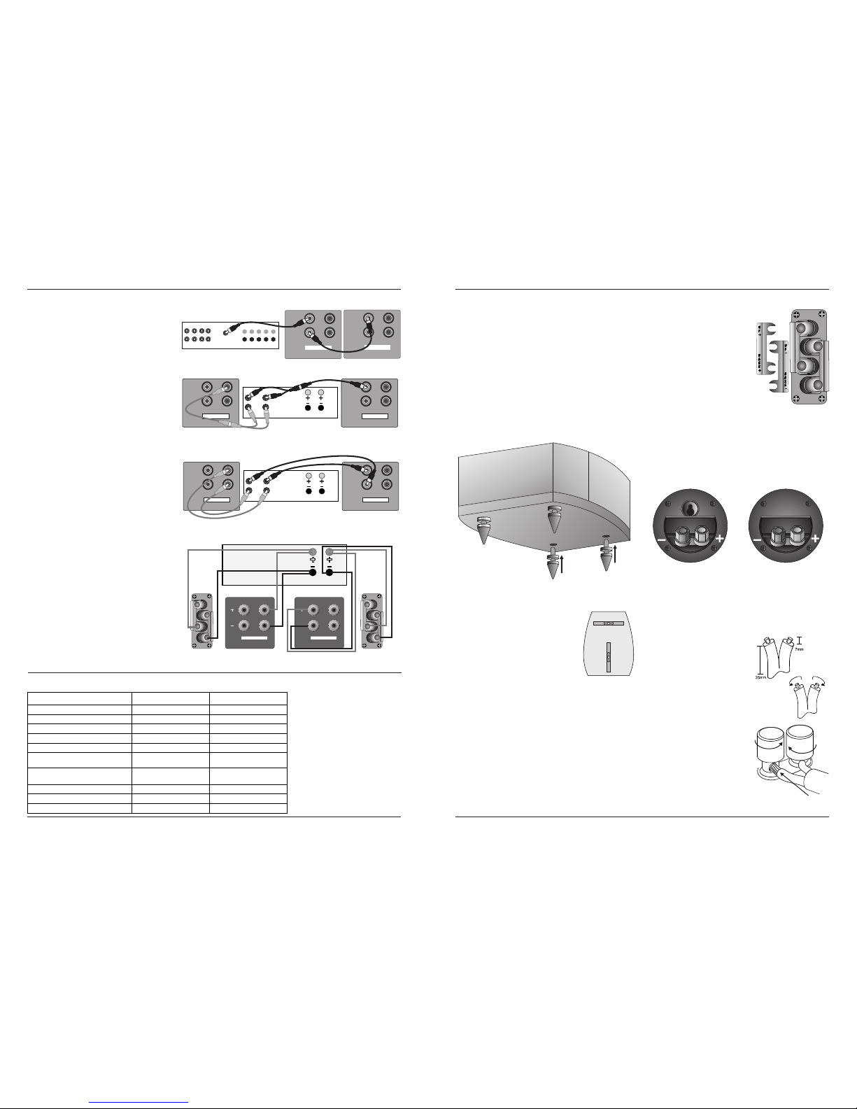
HOME CINEMA LINE CONNECTION
RIGHT CHANNEL
LEFT CHANNEL
LINE LEVEL
LEFT
INPUT
OUTPUT
RIGHT
SUBWOOFER
LINE LEVEL
LEFT
INPUT
OUTPUT
RIGHT
SUBWOOFER
LEFTRIGHT
AMPLIFIER
L
R
PRE
OUT
MAIN
IN
SUBWOOFER
OUTPUT
LINE LEVEL
LEFT
INPUT
OUTPUT
RIGHT
SUBWOOFER
LINE LEVEL
LEFT
INPUT
OUTPUT
RIGHT
SUBWOOFER
STEREO LINE CONNECTION A
STEREO LINE CONNECTION B
Model .
SW 150
SW 250
Format
Powered Subwoofer Powered Subwoofer
Drive Unit 250 mm long throw
250 mm long throw
Amplifier Power 150W 250W
Line Input Sensitivity 200mV for 75W 325mV for 150W
Averaged Max. O/P (@ 1M)
110 dB 113 dB
Frequency Response
(Boundary Position)
35 Hz – 110 Hz 30 Hz – 100 Hz
Low Pass Filter Frequencies
35 Hz – 85 Hz
(6x10Hz steps)
35 Hz – 85 Hz
(6x10Hz steps)
Phase Adjustment Switchable 0º - 180º Switchable 0º - 180º
Dimensions (H x W x D) mm 330 x 330 x 170 420 x 420 x 375
Height on Feet mm
360
478
SUBWOOFER SPECIFICATIONS
HIGH LEVEL SPEAKER CONNECTION
LEFT
SPEAKER LEVEL INPUTS
RIGHT
SUBWOOFER
LEFT
SPEAKER LEVEL INPUTS
RIGHT
SUBWOOFER
FRONT
LEFT
FRONT
RIGHT
AMPLIFIER
RIGHT
LEFT
FRONT
LINE LEVEL
LEFT
INPUT
OUTPUT
RIGHT
SUBWOOFER
LINE LEVEL
LEFT
INPUTINPUT
OUTPUTOUTPUT
RIGHT
SUBWOOFER
LEFTRIGHT
AMPLIFIER
L
R
PRE
OUT
MAIN
IN
Page 14
Page 3
Crossover Networks
PRELIMINARIES
Most speakers in the Diamond 9
Unpacking the Speakers
series use a specially designed bi-
Carefully remove each loudspeaker from its packing carton. Be
wireable crossover panel with four
especially careful when removing the polythene bag. DO NOT attempt to
terminal binding posts. Please follow
lift the loudspeaker by the polythene bag.
the drawing carefully to see the
Retain the packing for future use. If you decide to dispose of the packing,
correct orientation of the loudspeaker
please do so with regard to any recycling regulations in your area.
term inals. The u pper t ermina ls
connect to the treble unit, the lower
Retain the instructions. If you pass a product to a third party, please
pair to the bass unit. As supplied, the
include the instructions.
treble terminal pair is connected to the
Fitting the Plinth and Spikes (Models 9.4, 9.5, 9.6 only)
bass terminal pair via removable
Carefully invert each loudspeaker. Protect the top surface from
metal straps. These should be left in
scratches or damage when the loudspeaker is in the inverted position.
place for standard installations.
Each loudspeaker is provided with four spikes. Prepare the spikes as
The D9.0 compact monitor, the D9.CC compact Centre Channel speaker
shown and screw the spikes into the threads on the plinth. Return the
and the D9.SR use essentially the same circular section crossover panel.
loudspeaker to its normal position taking care not to cause damage with
These are illustrated below.
the spikes.
The D9 DFS uses a crossover network panel built into the speaker’s rear
wall. This is illustrated on Page 4.
None of the abovementioned loudspeakers are bi-wireable.
Choosing and Preparing Cables
When moving speakers, be careful not to let the spikes pierce objects or
Specialist audio cable offers better performance than general purpose
cables which may be concealed under the carpet. Never drag
'bell' or 'zip' wire.
loudspeakers. If you cannot lift them easily, get someone to assist you
Choose a cable of suitable diameter - cable that is too thin will limit the
dynamics of the sound and may impair the bass response. Audio cable
Adjusting the Spikes: Loosen the nut. Screw
is polarised, with two cores of different colours, or often a raised rib or
each spike in or out so that the speakers are
coloured tracer in the case of twin cable.
stable. The top surfaces of each loudspeaker
should be level and the speakers should be the
Split the twin cores to a depth of about
same height above the floor.
40mm. Carefully strip the insulation
from each end, leaving about 10mm of
When the speakers are in their final positions,
bare wire. If the cable is stranded, lightly
tighten all the nuts.
twist to gather any loose strands.
Stands and Brackets
Connecting Terminals
The 9.1, 9.2, and 9.3 are intended primarily for stand mounting, though
Unscrew the terminal. Thread the bared
they can be mounted on wall brackets or even on sturdy shelves. The
end of each cable through the hole in the
quality of loudspeaker stands greatly influences the performance of your
bottom of the terminal post. Ensure that
loudspeakers so do not use flimsy products.
there are no loose strands which may
The Diamond 9.0 may be stand or wall mounted. The rear panel has a
touch adjacent terminals. Re-tighten the
threaded insert for attaching a pair of suitable wall brackets.
terminal securely. The drawing on the
Centre Channel Loudspeakers
right illustrates the method.
Each centre channel loudspeaker is supplied with two sets of mounting
NOTE: When connecting loudspeakers,
feet. By using a combination of large and small feet the loudspeaker may
the cables to left and right channels
be angled to point directly at the listening position. This will be found
should ideally be of equal length,
useful when the centre speaker is positioned under the TV screen.
regardless of the d istance of the
speakers from the amplifier.
Surround Loudspeakers
These speakers are designed primarily for wall mounting, though they
may be stand or shelf mounted if required. Please see Page 5
D9.SR D9.0 & D9.CC
Positioning the Front Loudspeakers (...cont. from page 4)
magnetically shielded so they may be positioned close to TV screens
and monitors with no ill-effects or colour distortion.
D9 DFS Surround Loudspeakers
Centre Loudspeaker
The Centre channel loudspeaker should be positioned centrally between
the loudspeakers, close to the television and mounted above or below
the screen.
The loudspeaker should be located on
a stable flat surface to avoid any
cabinet movement at high sound
levels. If you mount the unit on top of
the television, move it forward so that
the front grille sits slightly in front of
the screen. This will reduce sound
D9 SR Surround Loudspeakers
reflections from the screen and the top
Before mounting the loudspeakers, establish the
of the cabinet.
location using the same criteria as for the D9 DFS.
The D9 CS and the D9 CM are supplied
Ensure the wall is sound and can easily support the
fitte d with mo unting fe et which
weight of the loudspeakers.
support the cabinet in a horizontal
The D9 SR is supplied with four mounting feet for shelf
position. Four extra feet are supplied to
or stand mounting. In addition the terminal panel has a
enable you to tilt the cabinet up or
built in mounting slot for wall fixing.
down so that the speaker points
directly at the listening position. This
Wall mounting the D9 SR: Ensure the wall is sound
facility is particularly useful where the
and can easily support the weight of the loudspeakers.
Centre speaker is mounted under the
Drill and fix a No. 8 screw and suitable wall plug at each chosen location.
screen.
The screw should protrude about 5mm from the wall. Connect the cable
to the speaker. Align the keyhole slot over the screw. Pull gently down to
NOTE: All Diamond 9 bookshelf and floorstanding loudspeakers are
secure the speaker.
The speakers should ideally be sited 600 mm-1.5 metres above the
listening position and 2.5-3.5 metres apart, central to the listener and
be hind the lis ten ing pos iti on,
preferably on a rear wall.
Ensure that the wall is sound and can
support the product. Drill two 5mm
holes in the wall 220mm apart. Fix a
suitable No 8 round head screw firmly
into each hole using appropriate wall
plugs. Leave a stub of 5mm protruding
from the wall.
Connect the loudspeakers. Align the
holes in the mounting brackets over
the screw and carefully lower the unit
onto the screws. The speaker should
now be securely attached with the
spacers resting against the wall. Now co nne ct th e
speakers to the amplifier.
Note: As an alternative, the D9 DFS can be shelf or
stand mounted. The badge on the D9 DFS can be
rotated to match the orientation of the loudspeaker.
If the
listening position is some distance
from a rear wall, the speakers may be
mounted on opposite side walls but
always behind the listening position.
2 - 4 metres
º
0
4
-
5
1
>0.7metre
9.0 - 9.3
>200 mm
9.4 - 9.6
>50 mm
DVD/ PROCESSOR
RACK
TV
X2
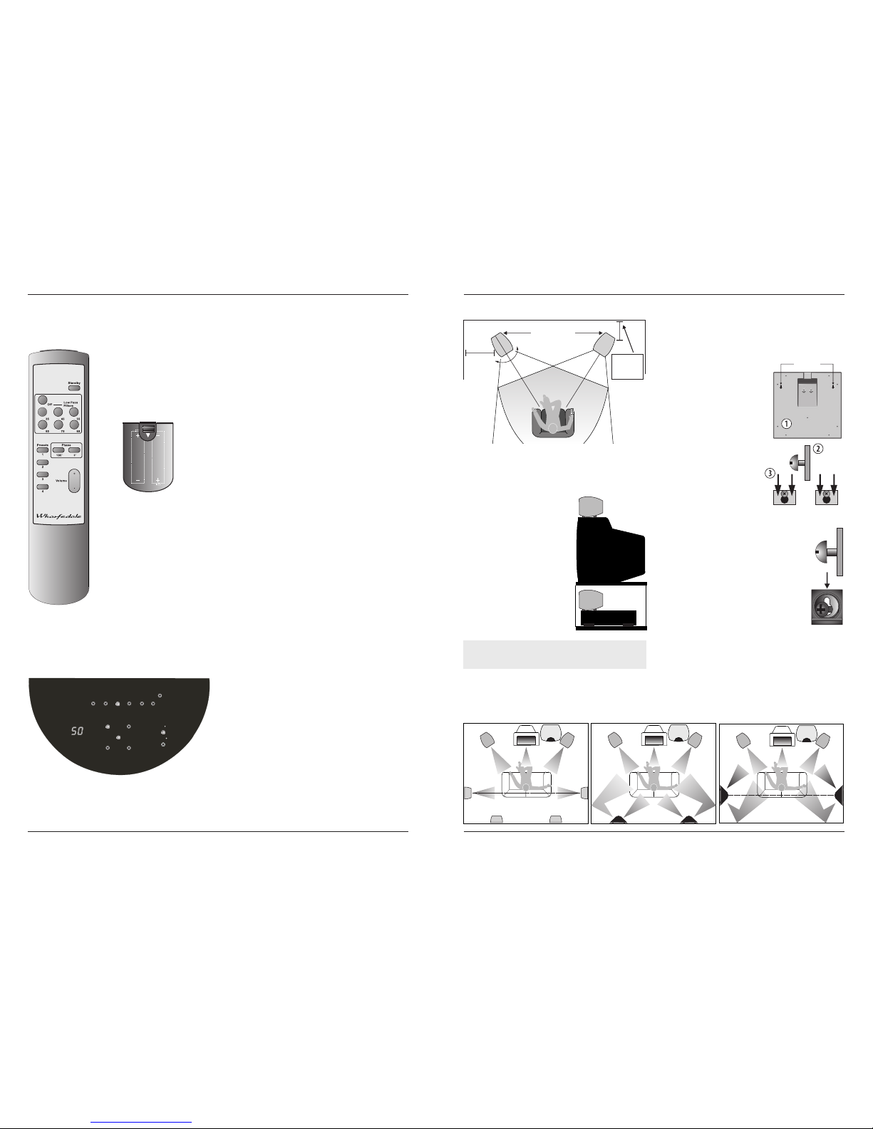
The diagrams below illustrate some typical Home Cinema room layouts.
System with Rear Mounted D9 DFS Surrounds
REAR
RIGHT
REAR
LEFT
FRONT
LEFT
FRONT
RIGHT
CENTRE
SUB
WOOFER
System with Side Mounted D9 DFS Surrounds
REAR
RIGHT
REAR
LEFT
FRONT
LEFT
FRONT
RIGHT
CENTRE
SUB
WOOFER
System with D9 SR Surround Speakers
ALTERNATIVE
POSITIONS
FRONT
LEFT
FRONT
RIGHT
CENTRE
SUB
WOOFER
ALTERNATIVE
POSITIONS
THE HOME CINEMA ENVIRONMENT
220 mm
Page 12
Page 5
Volume: Press the Volume + key to increase the volume level. Press the
OPERATING YOUR SUBWOOFER
Volume - key to decrease the volume level of the subwoofer. The volume
Remote Handset
range on the front panel display varies from 00 (minimum) to 99
All control functions are carried out using the remote handset.
(maximum).
Installing batteries
Low Pass Filters: Pressing the appropriate filter key will select the
frequency at which the subwoofer rolls off. The filter has steps at Off and
The handset operates on two LR6 (AA)
35Hz-85Hz in 10 Hz increments. When ‘OFF’ is selected the subwoofer
batteries which are supplied The battery
operates over its full designed range. Pressing other keys lowers the
compartment is located at the rear of the
maximum operating frequency. The Low Pass Filter value should be
handset. Unwrap the batteries and slide the
chosen having regard to the nature of the Front speakers and
cover off the handset. Place the batteries in
programme material. Follow the Setup Notes on Page 6 and the
the handset, the correct orientation is shown
instruction manual of your AV processor (if used) for more guidance.
on the diagram. When the batteries are
installed, replace the cover.
Phase: This key toggles the subwoofer between 0º and 180º phase shift.
Presets: Four different settings of level, frequency and phase can be
stored. Pressing and holding any of the preset keys on the remote for 3
seconds will cause the current settings to be stored in that preset. The
display will show the preset number then flash the preset number once
to show it has stored the preset.
To change from one preset to another, press a preset key on the remote
for less than 3 seconds to recall the settings of that preset. The display
will show the preset number:
If you select a preset and then alter any aspect of the setup, the preset
light will extinguish (as the setup no longer matches the preset).
Switching on the Subwoofer
Note: When brought out of standby for the first time, the unit will display
Check that all the connections to the
the factor y presets. Thereafter, bringing the unit out of standby will
subwoofer have been properly made and
revert it to the operational state last used. If you switch the power on and
that the system volume control is at
off at the rear panel while the unit is in standby, the unit will power up to a
minimum. Plug the supplied power cord into
normal operating state (i.e. not in standby). To enter standby, again
the mains socket on the rear panel. Plug the
press the Standby key.
mains plug into the wall socket and switch
the power on. Now switch the subwoofer on
SETTING UP YOUR SUBWOOFER
with the rest of your system. The subwoofer
General Notes
on/off switch has a rocker action; press the
Your subwoofer is most likely to be used with two typical programme
upper part to switch the equipment on and
sources, music and movies. The setup for these two very different
the lower part to switch it off. When switched
sources may be different if best results are to be achieved. Please read
on the light above the power switch will glow
these setup notes in conjunction with your processor and speaker
and the subwoofer will be operational.
manuals.
Operation - Controls and Functions
All setting up of the subwoofer should be performed with tone controls
and filters set ‘flat’.
Control functions are carried out using the remote handset. To operate,
Listening Rooms and Subwoofer Positioning:
the handset must be point at the subwoofer and be in direct line of sight.
Listening rooms are not ideal. Most rooms are reverberant with some
Standby: The Standby key brings the subwoofer in and out of Standby.
parallel walls. Because of room geometry and construction there will be
The drawing below shows a typical front panel display during operation.
areas with severe peaks at some frequencies and severe troughs at
others. These peaks and troughs are called ‘standing waves’ and if you
site loudspeakers in such areas the response will be highly non-linear.
With subwoofers this situation is exacerbated by the fact that it is easier
to treat high frequency irregularities by the use of drapes, soft
furnishings etc., but very hard to do the same at bass frequencies due to
the very long wavelengths - at 40 Hz the wavelength is almost 9 metres!
To help locate standing waves in your listening room, one idea is to sit in
the listening seat and recruit a friend with a deep voice to speak as he
moves around the area where you propose to site your subwoofer - you
will soon find out where not to site it! Where the voice sounds most
natural is a good place to start.
The low frequency response of the subwoofer and its blend with the main
loudspeakers is greatly affected by positioning. Although bass is
The preset light will not light if no preset has been set up or if a preset
enhanced by walls or corners, so often is coloration. As the drive unit
has been over-ridden.
faces downward, the floor will influence the sound. The surface under
In Standby mode all the lights on the subwoofer front panel are
the subwoofer should be stable and unobstructed. If the carpet is thick,
extinguished. The rear panel light remains on to show the unit is
consider placing the subwoofer on a solid surface such as a marble slab.
powered.
SUBWOOFER CONTROL
AA AA
OFF
LOW PASS FILTE R SELEC T
85Hz75Hz65Hz55Hz
45Hz
35Hz
MEMORY
POWER
PHASE
0
180
1 2
3
4
VOLUME
SW-250
 Loading...