

Page 1
™
PROFESSIONAL ACTIVE SUBWOOFER SYSTEM
Page 2

Page 3

Page
™
TABLE OF CONTENTS
1………………………………………………
2………………………………………………
3………………………………………………
4………………………………………………
5……………………………………………...
6……………………………………………...
7……………………………………………...
8……………………………………………...
9……………………………………………...
10………………………………………….…..
Unpacking - Warnings and Safety
Introduction
Warranty
Features
Description / Enclosure Features
Enclosure Call-Outs
Rear Panel Call-Outs
Operating Instructions
Connection Suggestions
Connection diagram #1
Connection diagram #2
11……………………………………….……..
12……………………………………….……..
13……………………………………….……..
Back Cover…..……………………….……..
Connection Diagram #3
Specifications
Dimensions
Contact Information
Page 4

™
UNPACKING
All Wharfedale Pro products are fully checked before leaving the factory. After
unpacking, inspect the contents for any physical damage. Retain the shipping carton
and internal packing material. Check as soon as possible that the unit is functioning
properly. In the event of any shipping damage, please contact your dealer and the
shipper immediately to make a claim.
WARNING AND SAFETY INSTRUCTIONS
1. READ INSTRUCTIONS carefully before operating this product.
2. RETAIN these instructions for future reference.
3. COMPLY WITH WARNINGS – All warnings and instructions for this product
should be adhered to.
4. SETUP PROCEDURES – In order to avoi d speaker damage, it is advisable to
establish and follow a pattern for powering on and off a sound system. Make sure that
all input and output level controls are at their minim um settings on all components of
the system. With all system parts connected, power on source equipment (playback
units, instruments, mixers, signal processors, etc.), BEFORE powering on any
amplifiers or powered speakers. Power on the system’s amplifier(s) or powered
speakers LAST. Wait until all system components have stabilized, then bring up
volume controls to operating level. Similarly, when shutting a system down, always
turn down all level controls and then turn off the amplifier(s) or powered speakers
BEFORE shutting down other system components.
5. CABLES – Be sure to use proper cables for all connections.
6. RIGGING – SUSPENDING – MOUNTING IS NOT RECOMMENDED FOR
THIS PRODUCT! The rigging, suspension or mounting of any speaker system can
expose members of the public to serious health risks and even death. UNDER NO
CIRCUMSTANCES ATTEMPT TO RIG, SUSPEND OR OTHERWISE MOUNT
SPEAKERS UNLESS YOU ARE FULLY QUALIFIED AND CERTIFIED TO DO SO
BY RELEVANT LOCAL, STATE AND NATIONAL AUTHORITIES. ALL RELEVANT
SAFETY REGULATIONS MUST BE FOLLOWED. IF YOU ARE NOT PROPERLY
QUALIFIED OR DO NOT KNOW OF PERTINENT REGULATIONS, CONSULT
QUALIFIED PERSONNEL FOR ADVICE AND ASSISTANCE.
7. CAUTION – These professional loudspeaker systems are capable of
generating very high sound pressure levels. Use care with placem ent and operation to
avoid exposure to excessive sound levels that could cause permanent hearing
damage.
8. SERVICING – The user should not attempt to service this product. Please
contact your local Wharfedale Pro Service Center.
1
Page 5

™
INTRODUCTION:
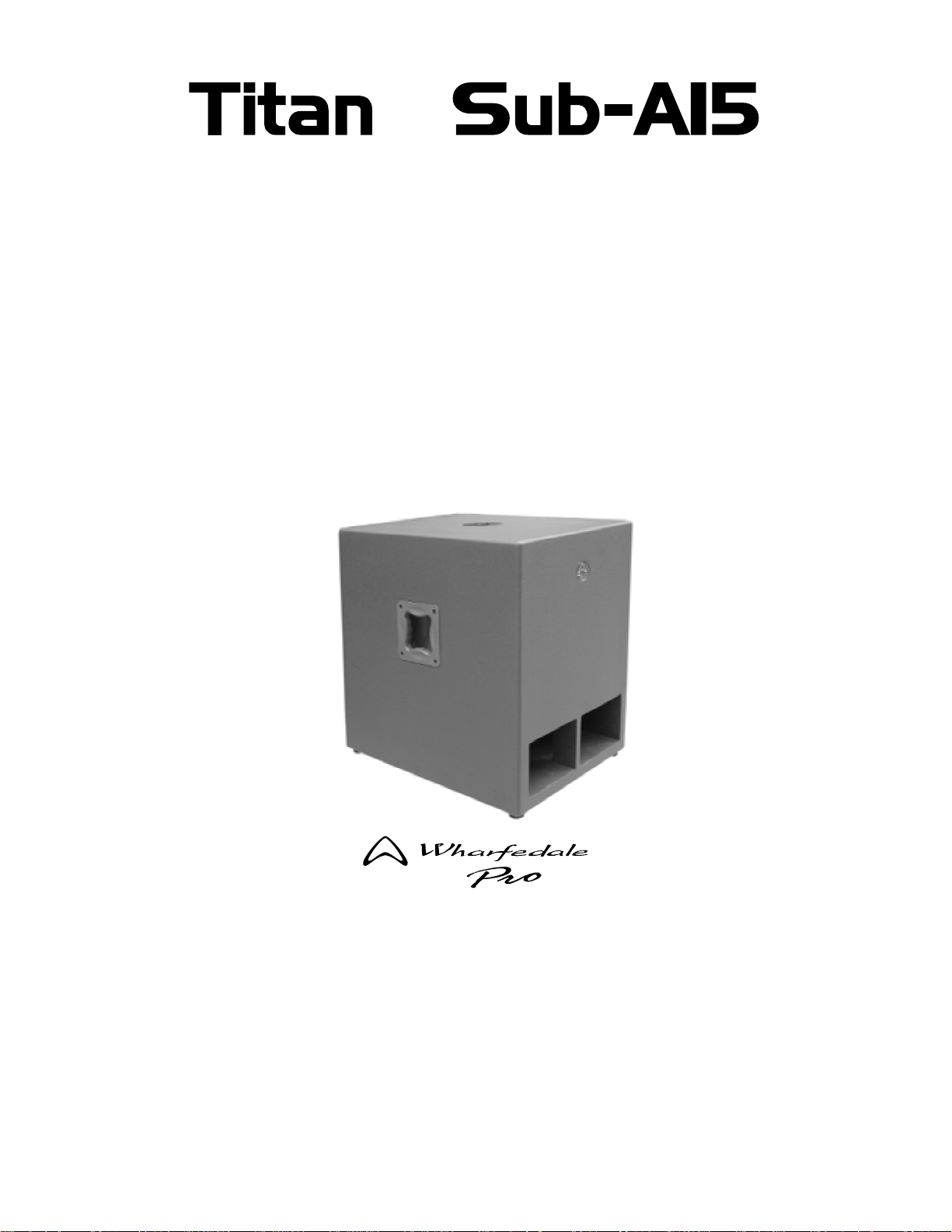
TITAN™ Sub-A15 Active Bandpass Subwoofer
Congratulations! You’ve made the smart move of choosing the new Wharfedale Pro
Titan™ Sub-A15, a powerful active subwoofer system designed to produce high quality
audio in any performance application.
A preeminent force in audio, with a long and distinguished history of innovation,
Wharfedale Loudspeakers was founded in 19 32 by Gilbert Briggs, who built his first
loudspeakers in a small village in the county of Yorkshire, England. This quiet market
town was located in the valley of the river “Wharfe” – an area known to this day as
“Wharfedale”.
A visionary in the field of loudspeaker technology, Briggs d eveloped the first two-way
loudspeaker – essentially the prototype of the modern loudspeaker. Today, as part of
International Audio Group, Wharfedale continues to grow as an intern ational standard
for professional loudspeakers.
In keeping with Gilbert Brigg’s original vision, all of our transducer components are
engineered, tooled, and manufactured in our 1,500,000 square foot factory facility. In
fact, Wharfedale is one of only a handful of manufacturers who still build all of their own
transducers.
All of which helps to explain how the new Titan Sub-A1 5 combines the newest
technologies, materials and design topology to ensur e ab solu te accur acy an d hig h
output.
Because of its functional cabinet design, the Titan Sub-A15 is versatile and app licable
in a variety of configurations. At home indoors or outdoors, on stage, in clubs, at
rehearsals, in theaters and houses of worship, the Titan Sub-A15 will provide the high
standards of low frequency audio reproduction that you require.
2
Page 6
™
WHARFEDALE PRO LIMITED WARRANTY
Wharfedale Pro Titan Sub-A15 subwoofers are warranted to be clear of manufacturing
or material defects for a period of one year from the origin al dat e of pu rch a se. In th e
event of malfunction, contact your authorized Wharfedale Pro dealer or distributor for
information.
*Be aware that warranty details may differ from country to country. Contact your dealer or distributor for
information. These terms do not infringe your statutory rights.
Wharfedale Pro website: www.wharfedalepro.com
Wharfedale Pro is a member of the International Audio Group (IAG)
IAG reserves the right to alter or improve specifications without notice.
All rights reserved ©2007
3
Page 7

™
TITAN Sub-A15 Band-Pass Active Subwoofer Features
- Peak limiter that protects the amplifier and speaker from clipping.
- 0°, 180° PHASE switch
- Built-in 600 watt (peak), 400 watt (continuous) amplifier
- Thermal, DC fault and short circuit protection
- Power on and system AGC protect LED indicators
- Integral preset limiter prevents clipping and distortion.
- Summed, stereo line level inputs combine the left and right signals to a single, mono
signal which is routed to the Titan Sub-A15’s internal amplifier. This feature allows for
the operation of a single subwoofer in stereo sound system. Integrity of the original
stereo input remains intact at the line level outputs.
- A pair of an integral crossovers send a high-pass, balanced, line-level, stereo signal
to a pair of powered satellite full-range speakers or an external amplifier for passive
satellite speakers.
- A speaker-level, 1/4” TS phone jack input is provided. This input is useful in
applications, where it may be more practical to use a full-range, amplified speakerlevel signal and connect it to the Titan Sub-A15 subwoofer.
4
Page 8

™
Titan Sub-A15 DESCRIPTION
The TITAN Sub-A15 is powerful 15 inch band pass active subwoofer. A built-in 400
watt (continuous) 600 watt (peak) amplifier conveniently accepts stereo or mono line
level inputs via dual, balanced, XLR-¼” “combo” connectors as well as a unique single
channel 4Ω speaker level input via a ¼” phone jack which allows for use with a
standard sound reinforcement amplifier (when the internal amplifier is not used).
A custom designed, down-firing, aluminium cast frame 15" woofer, with a 3" voice coil,
is utilized as the heart of the Titan Sub-A15's complementary low frequency
enhancement system. Integral signal processing includes a dynamic AGC (Automatic
Gain Control) circuit, a stereo crossover and signal limiting for the prevention of a
distorted signal to the internal amplifier. A convenient and an essential PHASE switch
is included to allow for proper subwoofer signal polarity to be selected.
A pair of balanced XLR male output connections, with switchable “High-Pass” mode
are available for the stereo line level outputs and may be used to pass through mono
or stereo signals from the inputs to another system or to send a high-pass, line-level
stereo signal to a pair of powered, full-range speaker s such as the popular Wharfedale
Pro Titan ACTIVE models.
ENCLOSURE FEATURES
-Custom 15” Low Frequency driver provides exceptional low-end clarity, high power
handling capability and maximum efficiency
-Rugged, textured grey, painted 18mm, 13 ply birch plywood enclosure with two
rubberized over-molded handles on the sides and four screw mounted rubber feet on
the bottom of the enclosure.
-Integral pole mount adapter for the mounting of speaker enclo sures above the
subwoofer.
5
Page 9

™
Titan Sub-A15 – ENCLOSURE CALL-OUTS
1. Pole mount socket
The top of the Titan Sub-A15 provides a convenient built in pole mount socket for
easy mounting of a standard 35mm diameter speaker pole (such as the Wharfedale
Pro SP-1) for easy top-side mounting of a mid/high passive or active speaker.
2. Integral Carry Handle
The Titan Sub-A15 has two rubber over-moulded carry handles (one on each side)
for easy transportation of the enclosure.
3. Rubber Feet
There are four skid-resistant screw mounted rubber feet on the bottom of the Titan
Sub-A15.
4. Ports
There are two ports on front of the Titan Sub-A15 that are reflex tuned to provid e
enhanced low frequency response from the enclosure.
3
INTEGRAL
2
HANDLE
RUBBER
FEET
CARRY
POLE MOUNT SOCKET
1
6
PORTS
4
Page 10

™
Titan Sub-A15 – REAR PANEL CALL-OUTS
1. INPUT A - Balanced line level input via a XLR / ¼” combo connection.
2. OUTPUT A - Balanced male XLR connection provides output “THRU” or HIGHPASS signal
(depending on switch setting).
3. SPEAKER LEVEL INPUT -
Allows for connection of the output of an external amplifier to use the Titan Sub-A15 as a passive
subwoofer.
NOTE: Disconnect the power cord when using the Titan Sub-A15 in this mode.
4. INPUT B - Balanced line level input via a XLR / ¼” combo connection.
5. OUTPUT B - Balanced male XLR connection provides output “THRU” or HIGHPASS signal
(depending on switch setting).
6. HEATSINK - Cooling fins for amplifier. Do not obstruct.
7. VOLUME CONTROL - Adjusts volume level of the subwoofer.
HEATSINK
VOLUME
CONTROL
THRU / HIGHPASS
SWITCH
PHASE SWITCH
LIMIT LED
POWER LED
POWER SOCKET
INPUT A
1
OUTPUT A
2
SPEAKER
3
LEVEL INPUT
INPUT B
4
5
OUTPUT B
INPUT
(BALANCED)
A
SPEAKER
LEVEL IN
B
(BALANCED) (BALANCED)
INPUT
OUTPUT
(BALANCED)
THRU
(100Hz)
HIGHPASS
OUTPUT
I
I
I
_
I
8
VOLUME
PHASE
0
I
I
I
I
I
MAX
I
0°
180°
WWW.WHARFEDALEPRO.COM
CAUTION
RISK OF ELECTRIC SHOCK
DO NOT OPEN
WARNING: SHOCK HAZARD DO NOT OPEN
AVIS: RISQUE DE CHOC ELECTRIQUE -NE PAS OUVRIR
LIMIT
ON
OFF
POWER
N 2082
AC 220-240V~50Hz 400W
FUSE T4AL250V
!
POWER SWITCH
SERIALNUMBER
8. THRU / HIGHPASS SWITCH - Selects the signal type that is routed to the OUTPUT jacks. “THRU” sends
the unprocessed signal to the outputs. “HIGHPASS” filters the signal and
only sends signals above 100Hz to the outputs.
9. PHASE SWITCH - Selects the polarity of the signal being sent to the subwoofer. 0° selects the signal
6
7
8
9
10
11
12
13
polarity as it appears at the input. The “180°” selection inverts the phase of the signal.
10. LIMIT LED – LED indicator illuminates when the signal limiting function is activated.
11. POWER LED - LED indicator illuminates when the unit is powered up.
12. POWER SOCKET - This is the connection for the IEC AC power connector.
13. POWER SWITCH – Turns the power on and off to the subwoofer amplifier module.
7
Page 11

™
Titan Sub-A15 OPERATING INSTRUCTIONS
The Titan Sub-A15 is easy to use! The steps below should be followed to help you get
the best performance out of your subwoofer and speaker system.
-Place the Titan Sub-A15 upright on its feet and place any pole mo unts or additional
speakers in place before making any wiring connections.
-Make all audio connections (as outlined below and on subsequent pages) before
turning on the power of any system components (see Page 1 “SETUP PROCEDURES”).
Once all of the connections are made, power up only the system mixer, processors and
any playback or auxiliary equipment BEFORE powering up the Titan Sub-A15 or any
other powered speakers or amplifiers or speaker damage may occur!
-Once everything is powered up, using a suitable signal source (such as talking into a
microphone, playing an instrument or signal from a playba ck unit), gradually turn up the
volume controls for all amplifiers and powered speakers and adjust the appropriate
mixer levels to a comfortable setting, being careful that signals are not distorting or
creating feedback.
CONNECTION SUGGESTIONS
There are several creative ways to connect and use the Titan Sub-A15. The following
pages show some suggestions for a few simple system configurations that can be used.
Variations on these suggestions can be easily developed to meet your specifi c needs.
CONNECTION DIAGRAM # 1 on page 9 shows the typical connection of a Titan SubA15 in a stereo sound system. OUTPUT A and OUTPUT B can be connected to a two
channel amplifier or a pair of powered speakers.
CONNECTION DIAGRAM # 2 on page 10 shows the connection of a Titan Sub-A15 as
a passive subwoofer system using an external amplifier that receives the low frequency
output of an electronic crossover.
CONNECTION DIAGRAM # 3 on page 11 shows the connection of two Titan Sub-A15's.
8
Page 12

™
CONNECTION DIAGRAM # 1
STEREO SYSTEM WITH HIGHPASS OUTPUT
Left
Output
Right
Output
TO LEFT ACTIVE SPEAKER
OR AMPLIFIER INPUT
INPUT
(BALANCED)
A
THRU /
HIGHPASS
switch in
“HIGHPASS”
(down) mode
SPEAKER
LEVEL IN
B
(BALANCED) (BALANCED)
INPUT
OUTPUT
(BALANCED)
THRU
(100Hz)
HIGHPASS
OUTPUT
I
I
I
_
I
8
VOLUME
PHASE
TO RIGHT ACTIVE SPEAKER
OR AMPLIFIER INPUT
0
I
I
I
I
I
+6
I
0°
180°
WWW.WHARFEDALEPRO.COM
CAUTION
RISK OF ELECTRIC SHOCK
DO NOT OPEN
WARNING: SHOCK HAZARD DO NOT OPEN
AVIS: RISQUE DE CHOC ELECTRIQUE -NE PAS OUVRIR
LIMIT
ON
OFF
POWER
N 2082
AC 220-240V~50Hz 400W
FUSE T4AL250V
!
MIXER
SERIALNUMBER
POWER
Switch in “ON”
(up) mode
POWER
CORD
NOTE: This same connection configuration can be used with OUTPUT A and B used in
a full-range mode when the THRU / HIGHPASS switch is in the “THRU” (up) position.
9
Page 13

™
CONNECTION DIAGRAM # 2
USING THE Titan Sub-A15 WITH AN EXTERNAL AMPLIFIER
TO SPEAKER LEVEL
INPUT
INPUT
(BALANCED)
A
SPEAKER
LEVEL IN
B
(BALANCED) (BALANCED)
INPUT
SERIALNUMBER
OUTPUT
(BALANCED)
THRU
(100Hz)
HIGHPASS
OUTPUT
I
I
I
_
I
8
VOLUME
PHASE
0
I
I
I
I
I
MAX
I
0°
180°
WWW.WHARFEDALEPRO.COM
CAUTION
RISK OF ELECTRIC SHOCK
DO NOT OPEN
WARNING: SHOCK HAZARD DO NOT OPEN
AVIS: RISQUE DE CHOC ELECTRIQUE -NE PAS OUVRIR
LIMIT
N 2082
!
WARNING!
DO NOT CONNECT
ON
OFF
POWER
AC 220-240V~50Hz 400W
FUSE T4AL250V
POWER CORD OR
TURN ON POWER
WHEN USING THIS
CONFIGURATION!
FROM LOW FREQUENCY
OUTPUT OF AN ELECTRONIC
CROSSOVER
AMPLIFIER OUTPUT
10
Page 14

FROM
MIXER
OUTPUT
LEFT
FROM
MIXER
OUTPUT
RIGHT
™
CONNECTION DIAGRAM # 3
USING TWO Titan Sub-A15's WITH TWO POWERED SPEAKERS
TO LEFT
MAIN
POWERED
SPEAKER
INPUT
(BALANCED)
A
SPEAKER
LEVEL IN
B
(BALANCED) (BALANCED)
INPUT
OUTPUT
(BALANCED)
THRU
(100Hz)
HIGHPASS
OUTPUT
0
I
I
I
I
I
I
I
I
_
I
8
MAX
I
VOLUME
0°
180°
PHASE
TO INPUT OF 2
SUBWOOFER
WWW.WHARFEDALEPRO.COM
CAUTION
RISK OF ELECTRIC SHOCK
DO NOT OPEN
WARNING: SHOCK HAZARD DO NOT OPEN
AVIS: RISQUE DE CHOC ELECTRIQUE -NE PAS OUVRIR
nd
ON
OFF
POWER
N 2082
AC 220-240V~50Hz 400W
FUSE T4AL250V
!
POWER
CORD
POWER
CORD
POWER
CORD
SERIALNUMBER
LEFT SIDE
SUBWOOFER
TO RIGHT
POWERED
SPEAKER
MAIN
INPUT
(BALANCED)
A
SPEAKER
LEVEL IN
B
(BALANCED) (BALANCED)
INPUT
SERIALNUMBER
OUTPUT
(BALANCED)
THRU
(100Hz)
HIGHPASS
OUTPUT
RIGHT SIDE
SUBWOOFER
0
I
I
I
I
I
I
I
I
_
I
8
MAX
I
VOLUME
0°
180°
PHASE
AVIS: RISQUE DE CHOC ELECTRIQUE -NE PAS OUVRIR
LIMIT
ON
OFF
WWW.WHARFEDALEPRO.COM
CAUTION
RISK OF ELECTRIC SHOCK
DO NOT OPEN
WARNING: SHOCK HAZARD DO NOT OPEN
N 2082
POWER
AC 220-240V~50Hz 400W
FUSE T4AL250V
!
POWER
CORD
11
Page 15

SPECIFICATIONS
™
Model Name
System Type
Frequency Response +/-3dB
Enclosure Material
Enclosure Colour
Frame material
Size (mm / inches)
Coil Size (mm / inches)
Impedance
Speaker Pole Adapter
Inputs A & B - Type / Connection
Output A & B Type / Connection
Input Sensitivity
High Pass Frequency Selection
TITAN Sub-A15
Band-pass subwoofer
45-150Hz
18mm Plywood
Grey
Die-cast aluminium frame
404mm / 15”
75 / 3”
4 ohm
Yes
Balanced Line Level inputs via two combo
connectors
Balanced Line Level outputs via two XLR-M
connections
0.775V
100Hz
Phase Switch Selection
Speaker Level Input Impedance
Speaker Level Input Connection
Amplifier Power:
Continuous
Peak
Protection Type
Power On Indicator
Dimensions (mm / inches):
Height
Width
Depth
Weight (Net) kg / lbs
Weight (Gross) kg / lbs
0° / 180°
1/4” TS Phone input
4Ω
400W
600W
Dynamic AGC
LED
630.0mm / 24.8"
478.0mm / 18.8"
640.0mm / 25.2"
45.48kg / 100.0lbs
50.26kb / 110.5lbs
12
Page 16

630.00
478.00
BACK VIEW
630.00
640.00
640.00
478.00
TOP VIEW
FRONT VIEWLEFT SIDE VIEW RIGHT SIDE VIEW
640.00
™
478.00
BOTTOM VIEW
640.00
630.00
13
Page 17

Page 18

Wharfedale International LTD.
IAG HOUSE
Sovereign Court, Ermine Business Park,
Huntingdon, Cambs,
PE29 6XU, England
www.wharfedalepro.com
IAG Professional reserves the right to alter or improve
specifications without notice.
All rights reserved © 2007 Wharfedale Pro
Wharfedale Pro is a member of the International Audio Group
 Loading...