

Page 1

Fax: 01480 431767
Tel: 01480 447700
Sovereign Court,
IAG House,
Audiolab
Huntingdon PE29 6XU
Ermine Business Park,
8000S
Integrated Amplifier
User Instructions
Page 2
1: Statutory & Safety Information
CAUTION!
RISK OFELECTRIC SHOCK
DO NOT OPEN
TO REDUCE THE RISK OF ELECTRIC SHOCK DO NOT REMOVE COVER
NO USER-REMOVEABLE PARTS INSIDE
REFER SERVICING TO QUALIFIED PERSONNEL
ADVERTISSEMENT : RISQUE DE CHOC ELECTRIQUE-
NE PAS OUVRIR
This symbol indicates that there are important
operating and maintenance instructions in the
literatureaccompanying thisunit.
This symbol indicates that dangerous voltage
constituting a risk of electric shock is present
withinthis unit.
4
ead these instructions.
Keep these instructions. Inthe event that you passthe product to a third
partythis instructionmanual shouldbeprovidedalong withthe product.
Heedall warnings.
Followall instructions.
Donot usethis apparatusnearwater.
Cleanonly withdry cloth.
Donot blockany ventilationopenings.
Installin accordancewith themanufacturer'sinstructions.
Do not install near any heat sources such as radiators, heat registers,
stoves,or otherapparatus (includingamplifiers)thatproduce heat.
Do notdefeat thesafety purposeof thepolarized orgrounding typeplug.
A polarized plug has two blades with one wider than the other. A
grounding type plug has two blades and a third grounding prong. The
wider bladeorthe thirdprongare provided foryoursafety. Iftheprovided
plug doesnotfit intoyour outlet, consultan electricianforreplacement of
theobsolete outlet.
Protect the power cord from being walked on or pinched, particularly at
plugs, convenience receptacles, and the point where they exit from the
apparatus.
Useonly attachments/accessoriesspecified bythemanufacturer.
Use only with a cart, stand, tripod, bracket, or table
specified by themanufacturer, or sold with theapparatus.
When a cart is used, use caution when moving the
cart/apparatuscombination toavoid injuryfromtip-over.
Unplug this apparatus during lightning storms or when unused for long
periodsoftime.
Refer all servicing to qualified service personnel. Servicing is required
when the apparatus has been damaged in any way, such as powersupply cord or plug is damaged, liquid has been spilled or objects have
fallen into the apparatus, the apparatus has been exposed to rain or
moisture,does notoperate normally,orhasbeen dropped.
Warning:
product to rainor moisture.The product mustnot be exposedto dripping
and splashing andno object filledwith liquids such as a vase offlowers
shouldbe placedon theproduct.
No naked flame sources such as candles should be placed on the
product.
Caution:
manufacturercould voidthe user'sauthoritytooperate this device.
This equipmenthas beentested andfound tocomply withthe limitsfor a
Class B digitial device, pursuantto part 15 of theFCC rules. These limits
are designed to provide reasonable protection against harmful
interference in aresidential installation. This equipment generates, uses
and can radiate radio frequency energy and, if not installedand used in
accordance withtheinstructions, maycauseharmful interferencetoradio
or television reception,whichcanbe determined bytuningtheequipment
off andon, theuser isencouraged totry tocorrect theinterference byone
ormore ofthe followingmeasures:
Re-orientate or re-locate the receiving antenna. Increase theseparation
between the equipmentand thereceiver. Connect theequipment into an
outleton acircuit differentfromthatto which thereceiver isconnected.
Consultthe dealeror anexperiencedradio/TVtechnician forhelp.
Important Note:
with care and not punctured or damaged. Used batteries should be
disposed of in full conformity with recycling regulations in your area.
NEVERdispose ofbatteries inafireor in thegeneral rubbish.
To reduce the riskof fireor electrical shock,do notexpose this
Changes or modifications not expressly approved by the
The batteriessupplied with thisunit shouldbe treated
Mains supply and safety
Mains Supply:
shown on therear panel. Ifthis does notmatch the voltagein your area,
consultyour dealer.
The mains supply fuse is located on the rear panel of the unit. If it has
broken, checkfor anyobvious causebefore replacingthe fuse withone of
thecorrect ratingand type.Thefusevalues are:
220- 240V(UK, Korea,etc.) T2.5AL 20mm SlowBlow
100- 120V(USA,Japan,etc) T4.0AL 20mm SlowBlow
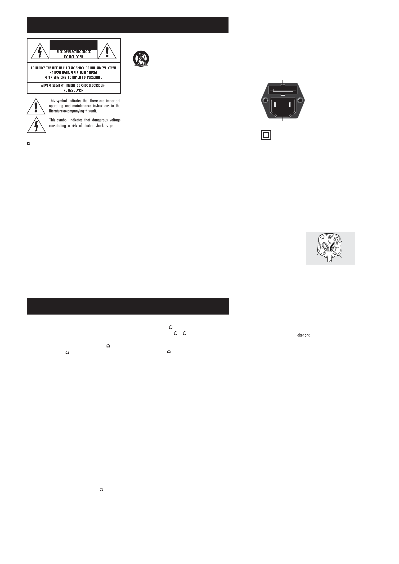
IEC Mains Connector
Power Cord:
suitable for yourarea. If youhave any doubts, consult your dealer about
obtaininga suitablepower cord.
The mains operating voltage of all Audiolab units is
Fuse Carrier
Class IIconstruction double insulated.This product mustnot be
connectedto earth.
An AC power cord is normally suppliedwith a mains plug
The fuse is located in a slide-in
carrier which also contains a spare
fuse. The fuse carrier can only be
pulled outafter the IECpower cordis
unplugged. When the carrier is
opened thefirst fuse tobeseenis the
spare fuse. Remove and safely
dispose of the fuse with the blown
linkbefore replacingit.
Important notice to UK users
The appliance cord is terminated with a UK approved mains plug fitted
with a5A fuse.If thefuse needsto bereplaced, anASTA orBSI approved
BS1362 fuse ratedat 5A must be used.If you needto change themains
plug, remove the fuse and dispose of this plug safely immediately after
cuttingit fromthe cord.
Connecting a Mains Plug
Thewires in themains leadarecolouredinaccordance with thecode:
Blue:NEUTRAL; Brown:LIVE:
As these colours may not correspond to the coloured markings identifying
theterminals in yourplug, proceedasfollows:
The BLUEwire must beconnected
to the terminal marked with the
letter N or coloured BLUE or
BLACK. The BROWN wire mustbe
connected tothe terminalmarked
with the letter L or coloured
BROWNor RED.
BLUE
(Neutral)
2.5A FUSE
BS 1362
BROWN
(Live)
6: Specifications 8000S
Rated Output Power
60 W (18 dBW) per channel into rated load impedance (8 Ohms)
withboth channelsdriven
Inputs
CD, TUNER, AUX, VIDEO, TAPE 1, TAPE 2: 125mV/20k IHF
POWERAMP:782 mV/47k
Gain
PRE-AMP:9dB@ 1kHz
POWERAMP:29.0 dB@1kHz.
Signal To Noise Ratio
CD,TUNER,AUX, VIDEO,TAPE1,TAPE2:
Betterthan 80dB(IHF,rel. 0.5V pre-ampoutput)
POWERAMP:better than80dB(IHF, rel.OdBW)
Frequency Response
CD,TUNER,AUX, VIDEO,TAPE1,TAPE2andPOWERAMP:
20Hz-20 kHz±0.5 dB: 1 Hz-65kHz-3dB.
Total Harmonic Distortion & Noise
Lessthan 0.07%
Channel Balance
Within1 dB
Channel Separation
Betterthan 60dB @1kHzanyinput
Crosstalk
Betterthan 80dB @1kHz
Polarity (phase)
Non-invertingfor allinputs andoutputs
Pre-amp Output
PREOUT 1and PREOUT2:OutputImpedance 100
MaximumOutput >7.3V RMS
9
9
9
Headphone Output
Outputimpedance: 330
(Suitablefor headphones8 -2 k impedance)
Record Output
VIDEOOUT,TAPE1OUT,TAPE2OUT:
Outputimpedance: 1k .
Gainfrom inputto recordoutput0dB (x1)
Muting
Mutingcontrolled manuallyor automatically
Accessories Supplied
ACPowerCord
InstructionManual
8000RCRemoteControlwith 2x AAbatteries
Colour
Silver
Operating Temperature Range
10-35°C
Power Requirements
50-60Hz 100 V, 110-120 V, and 220-240 V models available
MaximumPowerConsumption: 440VA
Dimensions
445x74x335mm -including feet,terminalsandcontrols
445x 64x 302mm-excludingfeet,terminals andcontrols
Weight
Net:7.4 kg
Shipping:8.8 kg
Audiolab reserves the right to alter design and specification
withoutnotice. Specificationmay varyfordifferentcountries.
Audiolabis amember oftheInternationalAudio Group.
9
9
(WXHXD)
99
(Dependingon Region)
Power Amplifier Protection Circuits
Short Circuit Protection:
is ashort caused bya faultyspeakeror connectinglead, theamplifierwill muteand
un-muteuntil thefault conditionisremoved.
DC Offset Protection:
voltage tobe presentedto the loudspeaker,the amplifierwill muteand staymuted
untilthe faultis removed.
Thermal Protection:
output devices are pushed beyond their safe operating area, the amplifier will
switchoff andthen switchbackonagain when ithas cooleddown.
Inall cases,if theamplifierdoesnot respond toremedial action,consultyour dealer.
If the outputterminals are connectedtogether or there
If thereis aninternal orexternal faultwhich maycauseDC
If the amplifieris driven excessivelyfor long periods,or the
Page 3

5: Service and Warranty
Servicing
Servicing of Audiolab products should only be carried out by
authorised service agents. If service is required the equipment
should be returned, securely packaged, preferably using original
packaging,toyourdealer.
In theUK equipment maybe returned tothe IAG ServiceCentre. In
the USAequipment maybereturned tothe Serviceaddress shown
onthis page.
Alwaystelephone beforereturning anyequipment.
A note should be enclosed giving your name, address, telephone
number,and abriefdescriptionof thereason forreturn.
If yourequire Serviceoutsidethe Warrantyperiod,do nothesitate
tocontact yourdealer.
While cleaning is in progress the AC power cord must be
unpluggedfrom theAC powersupplysocket.
Any grease or dirton the equipment maybe removed with asoft,
lint-free cloth slightly moistened with a mild solution of warm
water and detergent or washing-up liquid. Do not use any other
solutionsor solvents.
Retainoriginalpackagingfortransporting equipment.
If youhave anyqueries regardingtheuse ofAudiolab equipment,
consultyour dealer.
Service Addresses, UK & USA
IAG Service Centre
Unit 4
St Margaret’s Way
Stukeley Meadows Industrial Estate
Huntingdon
Cambs
PE29 6EB
England
Tel:+44 (0)1480
Fax: +44 (0)1480
452561
13403
IAG America, Inc.
15 Walpole Park South
Walpole
MA 02081
USA
Tel: +1 508 850 3950
Fax +1 508 850 3905
Audiolab limited warranty
Audiolab Ltd. warrants this product, subject to the terms and
conditions below, to be free from defects in materials and
workmanship. Duringthe warrantyperiodAudiolab willrepair or
replace (atAudiolab'soption) thisproduct,or anydefectivepart in
this product, if it is found to be defective due to faulty materials,
workmanship or function. The warranty period may vary from
countryto country.
Terms and conditions:
The warranty startsonthe date ofpurchase(orthe dateofdelivery
ifthis islater).
Youmust provide proof ofpurchase / delivery before workcan be
carried out. Without this proof, any work carried out will be
chargeableto you.
All work will be carried out by Audiolab or its authorised agents or
distributors. Any unauthorised repair or modification will void this
warranty.
If any partis no longeravailable it will replacedwith a functional
replacementpart.
Anyparts thatare replacedwillbecomethe propertyof Audiolab.
Any repairor replacementunder thiswarranty will notextend the
periodof warranty.
This warrantyis valid onlyin the countryofpurchase,applies onlyto
the firstpurchaser and isnot transferable.
The following are notcovered:
Products on which the serial number has been removed,
alteredor otherwisemade illegible.
Normalwear andtear andcosmeticdamage.
Transportationorinstallation ofthe product.
Accidental damage, faults caused by commercial use, acts of
God, incorrect installation, connection or packaging, misuse,
neglect orcareless operationor handlingoftheproduct which
isnot inaccordance withAudiolab'suserinstructions.
Equipment that has been operated in conjunction with
unsuitable,inappropriate orfaulty apparatus.
Repairs or alterations carried out by parties other than
Audiolabor itsauthorised agentsordistributors.
Productsnotpurchasedfrom anAudiolab authoriseddealer.
Productsthatwerenot newat thetimeoforiginal purchase.
Productssold'asis', 'asseen' or'withallfaults'.
Repairs or replacements as provided under this warranty are the
exclusive remedyof the consumer.Audiolab shallnot be liablefor
anyincidental orconsequentialdamagesfor breachof anyexpress
or impliedwarranty in thisproduct. Except tothe extent prohibited
by law,this warrantyisexclusive andinlieu ofallother warranties
whatsoever, both express and implied, including, but not limited
to, the warranty of merchantability and fitness for a practical
purpose.
This warranty provides benefits that are additional toand do not
affectyour statutoryrights asaconsumer.
Some countries and US states do not allow the exclusion or
limitation of incidental or consequential damages or implied
warranties so the exclusions in the paragraph above may not
apply toyou. Thiswarranty givesyou specificlegal rights,and you
may have other statutory rights, which vary from state to stateor
countryto country.
How to claim:
To obtainwarranty servicecontact theAudiolab authoriseddealer
from which you purchased this product. Do not despatch goods
without the prior agreement of the dealer, Audiolab or their
authoriseddistributors.
If asked to return products for inspection and/or repair, pack
carefully,preferablyinthe originalcartonsorpackagingaffording
an equal degree of protection, and return prepaid. If unsuitable
packaging is used,Audiolab may makea charge forthe supply of
newpackaging.
Insurance is recommended as goodsare returned at owner's risk.
Audiolab ortheir authorised distributorscannot beheld liable for
lossor damagein transit.
Packing,insurance andfreight onthe return journeywill bepaid by
Audiolab or their authorisedagents or distributorif corrective work
provestobenecessary.
2: Introduction
RECORD
SELECTOR
Unpacking
Unpackthe productfully.The cartonshould contain
TheAudiolab 8000Sintegrated amplifier
OneIEC powercord suitableforyourarea
OneRemoteHandsetwith twoAA batteries
Thisinstruction manual.
If any item is missing or damaged report this to your dealer as
soonas possible.
Retain the packing for future safe transport of your amplifier. If
you dispose of the packing, do so with regard to any recycling
regulationsin yourarea.
Inserting Batteries in the Handset
Thebattery compartmentis ontherearof the handset.Unwrap the
batteries, open the compartment cover and insert the batteries.
Followthe polarityindications inthebatterycompartment.
Always replace batteries in pairs. Use new batteries of the same
typeand rating,ideallyfrom thesame manufacturer.
Controls And Functions
Power Switch
When power is switched on the 8000S is muted for 8 seconds.
INPUT
SELECTOR
MODE
SWITCH
Alwaysswitch thepower off before changingconnections.
Input Selector
Turn toselectthe listeningsource.The 8000Smutes brieflywhena
newinput isselected.
Volume Control
Adjustsplaying volume.Always turnthevolumeup gradually.
Record Selector
Turn to select source to record to Tape 1, Tape 2 or Video. The
connections can also be used to connect to any recorder with
analogueinputs suchas aCD,MP3, DATrecorder,etc.
Record selector and input selector operate independently. It is
possibleto recordfrom anysourcewhilstlistening to another.
Mode Switch
Select integrated when using 8000S as an integrated amplifier.
Select mute to turn off pre-amplifier outputs, loudspeakers or
headphones.See section4 forfurtherdetails.
Headphone Socket
Socket for connection of headphones. Unplug headphones when
not in use. Connecting headphones mutes the loudspeakers and
disconnectsthe pre-amplifieroutputsandpoweramplifierinputs.
MUTE LED
RED=Mute On
REMOTE
CONTROL SENSOR
POWER LED
RED=Power On
VOLUME
CONTROL
Remote Handset
Buttonsshown inwhite controlthe8000S.
Buttons shown in grey operate Audiolab CD
playersand haveno effectonthe8000S.
As the handset uses RC5 coding it willoperate
manyother players.Check withyourdealer.
Mute
Toggles mute On/off. Does not function if the
MODEswitch onthe frontpanelisset to mute.
Input
Press to select listening source. The INPUT
selectoron thefront panelturns.
If you wish to record,the record input must be
selectedmanually.
Volume
Press to raiseor lower thevolume. The
VOLUMEcontrolonthe frontpanel turns.
HEADPHONE
SOCKET
POWER
SWITCH
Page 4

3: Input & Output Connections
FUSE
HOLDER
MAINS
INPUT
RIGHT
LOUDSPEAKER TERMINALS
Signal Connections
CD,TUNER, AUX, VIDEOIN,TAPE1IN,TAPE2 IN
Thesix inputsmay beusedforconnecting any linelevel source.
VIDEO OUT,TAPE1 OUT,TAPE2 OUT
Three sets of record outputs for connection of up to three stereo
audio recorders, e.g. tape recorder, CD recorder, audio recording
inputof VCR,DVD,MP3,MiniDisc recorder,etc.
PRE-AMP OUT 1 &2
Low impedance (100 ohm) pre-amplifier outputs for driving
external poweramplifiers, sub-woofersor signalprocessors.Long
cables may be used ifrequired. Pre-amp outputs are switched off
whenintegrated modeis selectedorwheneveramplifier ismuted.
POWER AMP IN
For driving the power amplifier input directly from an external
source.Only operateswhen prepowerAVmodeis selected.
LOUDSPEAKER TERMINALS
Twosetsof loudspeakeroutputterminals connectedin parallel.
GROUND
Use only if phono pre-amplifier and turntable are used andboth
are ClassIIdouble insulated(noearth connection).In thiscasethe
ground terminalcan be connectedto themetalwork of these units
to eliminateresidual hum. Theground terminalmust notbe used
asa safetyearth. Ifindoubtconsult your dealer.
LEFT
POWER
AMPLIFIER
INPUT
PRE-
AMPLIFIER
OUTPUTS
TAPE 2 TAPE 1
Standard Loudspeaker Connection
You can connect a speaker switching box or headphone adaptor to the unused set of speaker terminals
Bi-Wired Loudspeaker Connection
Loudspeaker bi-wiring offers improved sound quality because high and low frequency signals are carried
individually to the loudspeaker drive units.
VCR
CDR,ETC
AUX
Connecting Loudspeakers
Switchpower offwhen connectingloudspeakers.
Usegood qualitylow resistanceloudspeakercable.
Connect the Positive RED (+) terminal of the
amplifier to the Positive (+) RED terminal of the
loudspeaker. Connect the Negative (-) BLACK
terminalssimilarly.
When connecting loudspeakers tighten the
terminalssecurely byhand.
Makethere areno loosestrands ofwirewhichcould
causeshorts.
Speaker
7mm
Cables
20mm
Connecting
Cables
RED
BLACK
CD, DVD
4: Operation
Operating Modes
Although the8000S is anintegrated amplifier, itcan functionas a separatepre-amplifier and
poweramplifier.This allowstheunit tobe usedinavariety of stereoand multichannelmodes.
NOTE: When switching modes, the making and breaking of connections may momentarily
operatethe mutingfunction onthe8000S.
Integrated Mode
The pre-amplifier section isinternally connected to thepower amplifier. Pre-amp outputsare
notoperational. Externalsubwoofers, processors,oramplifierswill notreceive anysignal.
Pre-Power Mode
The pre-amplifier section is internally connected to the power
amplifier.The pre-amplifieroutputs areoperational.
A powered subwoofer can be connected to the pre-amplifier
outputs
A second power amplifier can be connected for bi-amplifying as
shownin thediagram.
An additional power amplifier can also be connected to drive a
secondpair ofspeakers inaremotelocation.
PRE-AMP OUT1&2POWER AMPIN
PRE-POWER
INTERNAL LINK
-ACTIVEACTIVE
LOUDSPEAKERS
--ACTIVE-
-ACTIVE--
OPERATIONALACTIVE--
OPERATIONAL-ACTIVE-
OPERATIONAL
Pre Mode
All signals to and from the power amplifier of the 8000S are
disconnected. In this mode, the 8000S functions as a stand-alone
pre-amplifier.
The pre-amplifier section of the 8000S can be connected to a
stereopower amplifier,or totwomonobloc amplifiers .
Pre-Power AV
The pre-amplifier and power amplifier sections operate
independently. This mode can be used to connect a multichannel
AVprocessor.
The processorshouldbe connectedviaany sparetapeoutput or,as
analternative, oneof thepre-ampoutputs.
SPKRS
OUTPUTS
INPUT
A/V PROCESSOR
Switching On
Makesureallthe connectionsto andfromtheamp aresecure andcorrect.
Makesuretheoperating modeis correctlyset.
Plug thepowercordinto thewallsocketand theamplifier.Switch onatthemains
andthen switchon the8000S.Thepowerindicatorlights. Theunit isoperational.
Theamplifier maybe operatedviathefront panelor theremotehandset.
NOTE: SelectingMUTEfrom thefront panelwilldisable themutefunction onthe
handset.Torestore normaloperation, selectanoperatingmode.
 Loading...