

Page 1

WSEDU09
ILLUSTRATED ASSEMBLY MANUAL
whadda.com
Page 2
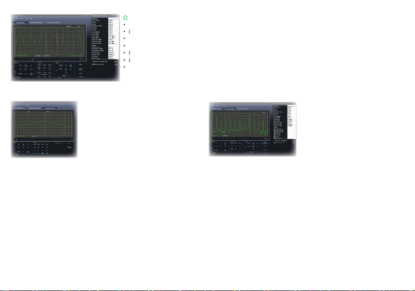
Oscilloscope
• bandwidth: DC to 200 kHz ± 3 dB
• input impedance: 100 kohm / 20 pF
• maximum input voltage: 30 V (AC + DC)
• time base: 10 µs to 500 ms per division
• input range: 100 mV to 5 V/division
• input sensitivity: 3 mV display resolution
• readouts: True RMS, dBV, dBm, p to p,
Duty cycle, Frequency…
• record length: 1k samples
sampling frequency: 62.5 Hz to 1.5 MHz
•
• sample history function
• auto set-up function
• pre-trigger function : on 0.1 ms/div .. 500 ms/div ranges
• persistence options: Colour graded, Variable and Innite
• timescale: 20 ms/div to 2000 s/div
• max. recording time: 9.4 h/screen
• automatic storage of data
• record and display of screens
• automatic recording for more than 1 year
• max. number of samples: 100/s
• min. number of samples: 1 sample/20 s
General information
• markers for: amplitude/voltage & frequency/time
• expert or basic mode selection in software
• input coupling: DC and AC
• 8 bit resolution
• storage of display and data
• power supply through USB: +/- 200 mA
• uses Microsoft® human interface device (HID) driver, no
external driver required
• dimensions: 94 x 94 mm / 3.7 x 3.7”
* Windows™ is a registered trademarks of Microsoft Corporation
Spectrum AnalyzerTransient Recorder
Min. system requirements
• IBM compatible PC
• Windows® XP, Vista, 7, 8 *
• SVGA display card (min. 1024 x 768)
• mouse
• free USB port 1.1 or 2.0
• frequency range: 0 .. 150 Hz to 75 kHz
• operating principle: FFT (Fast Fourier
Transform)
• FFT resolution: 512 lines
Page 3
1. Assembly (Skipping this can lead to troubles ! )
Ok, so we have your attention. These hints will help you to make this project successful. Read them carefully.
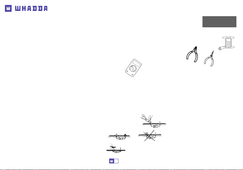
1.1 Make sure you have the right tools:
• A good quality soldering iron (25-40W) with a small tip.
• Wipe it often on a wet sponge or cloth, to keep it clean; then apply solder to the tip, to give it a wet look. This is called ‘thinning’ and
will protect the tip, and enables you to make good connections. When solder rolls o the tip, it needs cleaning.
• Thin raisin-core solder. Do not use any ux or grease.
• A diagonal cutter to trim excess wires. To avoid injury when cutting excess leads, hold the lead so they cannot
y towards the eyes.
• Needle nose pliers, for bending leads, or to hold components in place.
• Small blade and Phillips screwdrivers. A basic range is ne.
) For some projects, a basic multi-meter is required, or might be handy
1.2 Assembly Hints :
• Make sure the skill level matches your experience, to avoid disappointments.
•
Follow the instructions carefully. Read and understand the entire step before you perform each operation.
• Perform the assembly in the correct order as stated in this manual
• Position all parts on the PCB (Printed Circuit Board) as shown on the drawings.
• Values on the circuit diagram are subject to changes, the values in this assembly guide are correct*
• Use the check-boxes to mark your progress.
• Please read the included information on safety and customer service
* Typographical inaccuracies excluded. Always look for possible last minute manual updates, indicated as ‘NOTE’ on a separate leaet.
0.000
1.3 Soldering Hints :
1. Mount the component against the PCB surface and carefully solder the leads
2.
Make sure the solder joints are cone-shaped and shiny
3. Trim excess leads as close as possible to the solder joint
3
Page 4
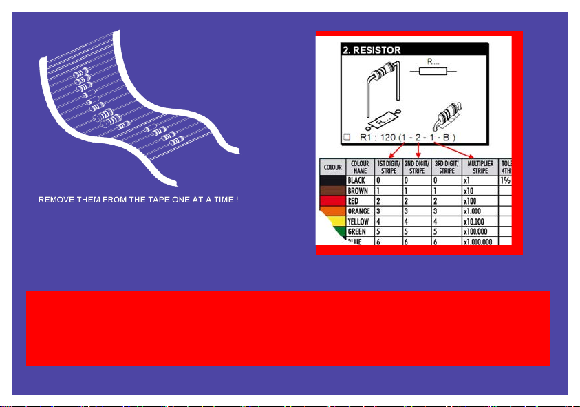
DO NOT BLINDLY FOLLOW THE ORDER OF THE
COMPONENTS ON THE TAPE. ALWAYS CHECK THEIR
VALUE WITH THE PARTS LIST!
- 4 -
Page 5
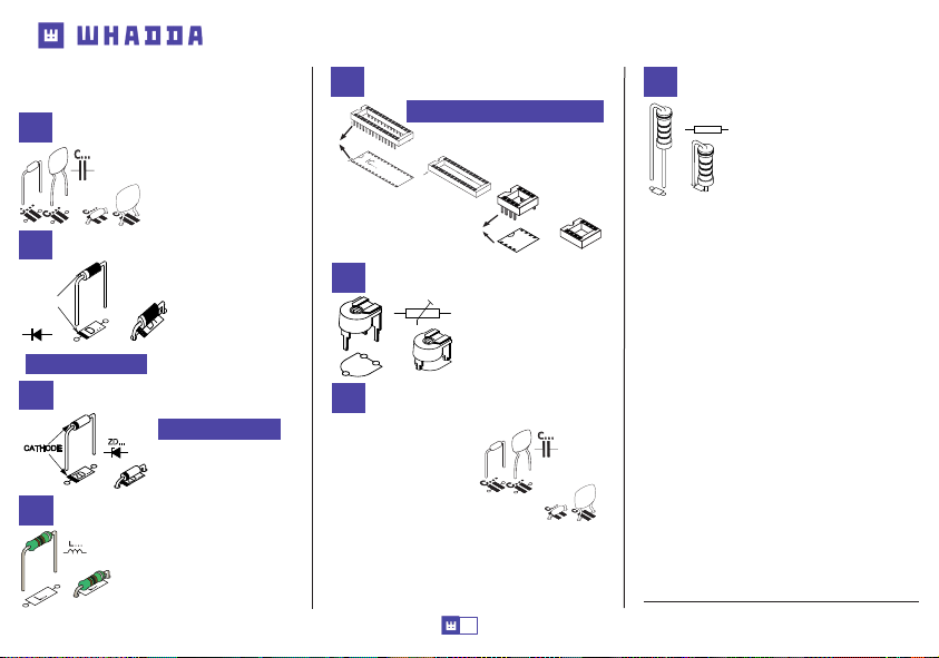
Construction
c...c...
CATHODE
D...
c...c...
CONSTRUCTION
1
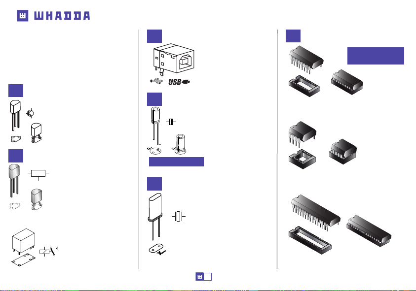
Ceramic Capacitors
C11...C13 : 100nF (104)
C16...C19 : 100nF (104)
2
Diodes
Watch the polarity!
3
Zenerdiode
CATHODE
4
L . . .
ZD...
.
.
.
.
D
.
.
Z
D
Z
Choke
L1 : 100µH (1 - 0 - 1 - B)
L . . .
L2 : 100µH (1 - 0 - 1 - B)
L . . .
D1 : BAT85
D2 : BAT85
D3 : BAT85
D4 : BAT85
D5 : BAT85
D6 : BAT85
D7 : BAT85
Watch the polarity!
ZD1 : 5V1
5
IC socket
Watch the position of the notch!
!
IC1 : 16p
IC2 : 8p
IC3 : 28p
6
Trimmer
7
Ceramic Capacitors
C1 : 2,2pF (2.2)
: 6,8pF (6.8)
C2
C3
: 10pF (10)
C4
: 15pF (15)
C5
: 27pF (27)
C6
: 27pF (27)
C7
: 47pF (47)
C8
: 100pF (101)
C9
: 470pF (471)
C10
: 680pF (681)
C14
: 1µF (105)
C15 :
1µF (105)
!
RV1 : 4K7
5
1
IC...
IC...
1
C20 : 1µF (105)
C21
: 1µF (105)
C22 :
1µF (105)
C23
: 1µF (105)
C24
: 1µF (105)
8
Vertical resistors
R...
R1 : 2,2Ω (2 - 2 - B - B)
R2 : 2,2Ω (2 - 2 - B - B)
R3 : 100Ω (1 - 0 - 1 - B)
R4 : 100Ω (1 - 0 - 1 - B)
R5 : 680Ω (6 - 8 - 0 - B)
R6 : 680Ω (6 - 8 - 0 - B)
R7 : 680Ω (6 - 8 - 0 - B)
R8 : 1KΩ (1 - 0 - 0 - 1 - 1)
: 1KΩ (1 - 0 - 0 - 1 - 1)
R9
R10 : 1KΩ (1 - 0 - 0 - 1 - 1)
R11 : 1KΩ (1 - 0 - 0 - 1 - 1)
R12 : 1KΩ (1 - 0 - 0 - 1 - 1)
R13 : 1KΩ (1 - 0 - 0 - 1 - 1)
: 1K1 (1 - 1 - 0 - 1 - 1)
R14
: 1K5 (1 - 5 - 2 - B)
R15
R16 : 1K5 (1 - 5 - 2 - B)
R17 : 2K2 (2 - 2 - 2 - B)
R18 : 2K7 (2 - 7 - 2 - B)
R19 : 5K1 (5 - 1 - 0 - 1 - 1)
: 7K5 (7 - 5 - 0 - 1 - 1)
R20
: 10KΩ (1 - 0 - 0 - 2 - 1)
R21
: 10KΩ (1 - 0 - 0 - 2 - 1)
R22
* metallm resistor !
*
*
*
*
*
*
*
*
*
*
*
Page 6
R23 : 11KΩ (1 - 1 - 0 - 2 - 1)
XX.. .. .. . .
R24 : 15KΩ (1 - 5 - 0 - 2 - 1)
R25 : 20KΩ (2 - 0 - 0 - 2 - 1)
R26 : 20KΩ (2 - 0 - 0 - 2 - 1)
R27 : 20KΩ (2 - 0 - 0 - 2 - 1)
R28 : 75KΩ (7 - 5 - 0 - 2 - 1)
9
Transistors
T1 : BC337
T2 : BC337
T3 : BC327
T...
10
Voltage regulator
VR...
*
*
*
*
*
*
12
USB connector
SK3
13
Electrolytic capacitors
C...
Watch the polarity!
Quartz crystal
14
C25 : 10µF
C26 : 10µF
C27 : 10µF
C28 : 10µF
C29 : 10µF
C30 : 100µF
C31 : 100µF
15
IC’s
IC1 : CD74HCT4052E
IC2 : TLV272IP
Construction
Watch the position of
the notch!
VR...
Relay switch
11
VR1 : LM317LZ
RL1 : TSC-106D3H or eq.
X1 : 4MHz
6
IC3 :VKEDU09
(programmed PIC18F24J501-ISP)
Page 7
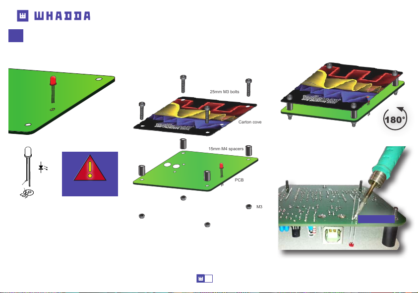
16
LED
STEP 1: Mount the LED.
Do not solder yet.
STEP 2: Assemble the unit but do not yet tighten
the bolts. Position the LED so that it stays just below
the cover plate.
25mm M3 bolts
Carton cover
15mm M4 spacers
Construction
STEP 3: Turn the unit 180°
STEP 4: Solder one lead and check the
position. If OK, solder the second
connection.
CATHODE
LD1 :
LD1
red
Watch the polarity!
PCB
M3 nut
SOLDER
STEP 5: Disassemble the unit.
7
Page 8
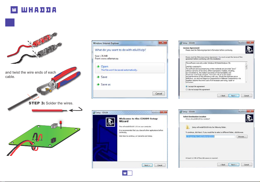
Mounting the test leads
17
STEP 1: Cut o the banana plug from the test
leads.
STEP
2: Strip both cables
and twist the wire ends of each
cable.
software installation
Step 1: Download the WSEDU09 software on our website
Step 2: open the le en select the software.
Step 4: Accept the license argeement
Assembly
STEP 3: Solder the wires.
STEP 4: Mount both cables as shown in the
drawing.
-
+
t with one cable and then do the other.
Tip: Star
Step 5: Solder the cables on the PCB.
Step 3: Select “next” to begin the installation
procedure.
8
Step 5: Select the destination on your PC
Page 9
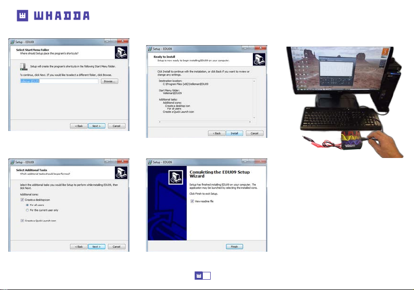
Step 6: Select the start menu folder
Step 8: Select “Install” for installing the
software.
Software installtion
Step 10: Connect the unit with the pc.
Step 7: Select additional tasks you would like
to be performed.
Step 9: Click “nish” to exit setup
9
Page 10
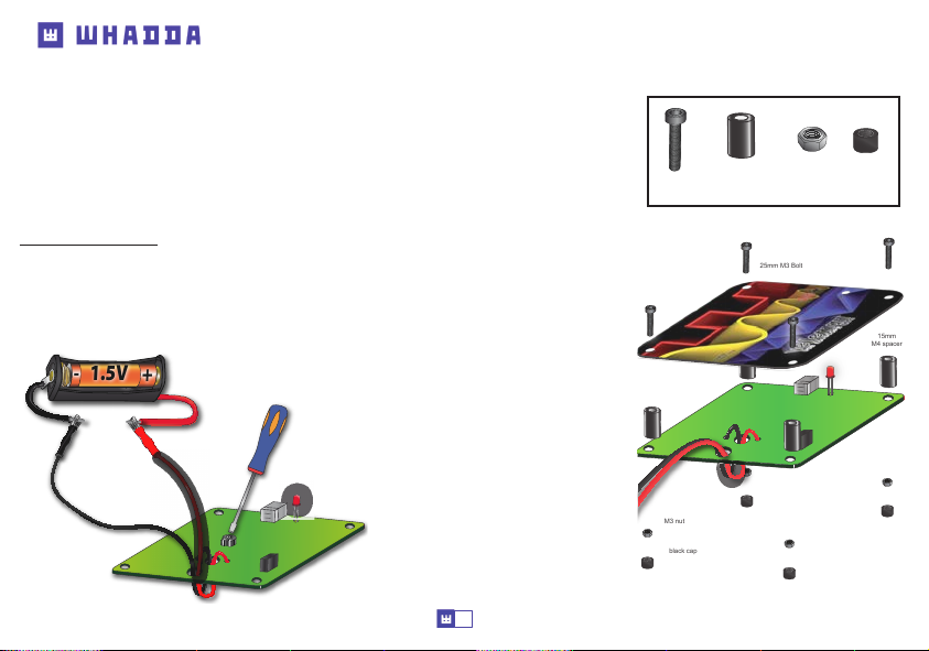
Calibration & assembly
CALIBRATION
There is no external driver necessary, the WSEDU09 uses the internal Microsoft Windows HID driver,
these will loaded automatic.
• Set RV1 to the middle position.
• Connect the WSEDU09 oscilloscope to the USB slot of the PC. The red led should light.
• Run the installed software WSEDU09.EXE
• If it is connected for the rst time, calibration procedure will start automatically.
• If it does not start automatically: In the Options menu select “Calibrate” and then click OK to
start the calibration. Wait until calibration is successful.
Advanced calibration: Fine tuning of the input amplier circuit
This calibration is not really necessary, you must only do this, if you want a higher precision of your
measurements
• In the ‘Options’-menu select “Expert Settings”.
• In the ‘View’-menu select “Waveform Parameters...”.
• In the ‘Waveform Parameters’-window select the check box “DC Mean”.
• Measure the output of the battery with a multi-
-
1.5V
+
+
-
+
meter and remember it.
• Connect the battery to the oscilloscope’s input.
• Set Volts/Div. to “0.5V” and click the “Run”
button.
• Adjust trimmer RV1 until the displayed “DC
Mean” value in the ‘Waveform Parameters’window corresponds with the measured value.
• Remove battery.
(requires a 1.5V battery)
10
ASSEMBLY
Bolts
Distance bolts
(4x)
Mount the cover.
M3 nut
black cap
Your scope is now ready for use.
(4x)
25mm M3 Bolt
Nuts
(4x)
Caps
(4x)
15mm
M4 spacer
Page 11
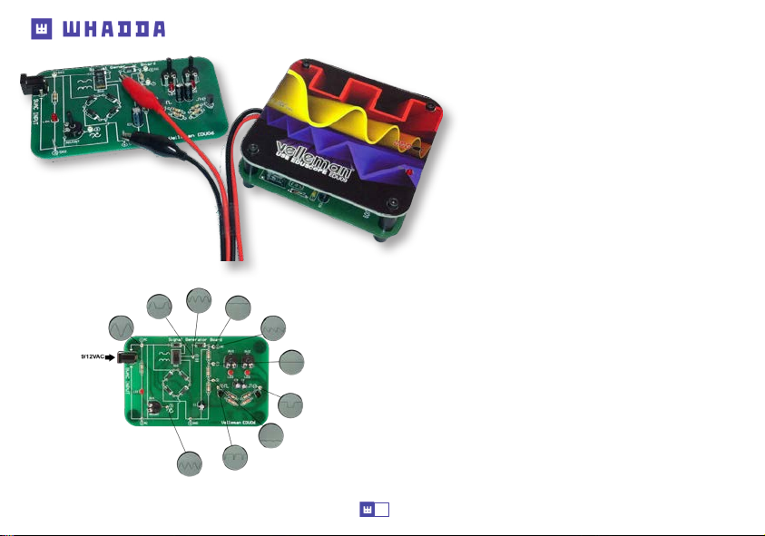
Experiments
Make sure to check out our WSEDU6 Oscilloscope
tutor kit. It features lots of information and a number of
experiments to familiarise yourself with the basics of an
oscilloscope.
11
Page 12
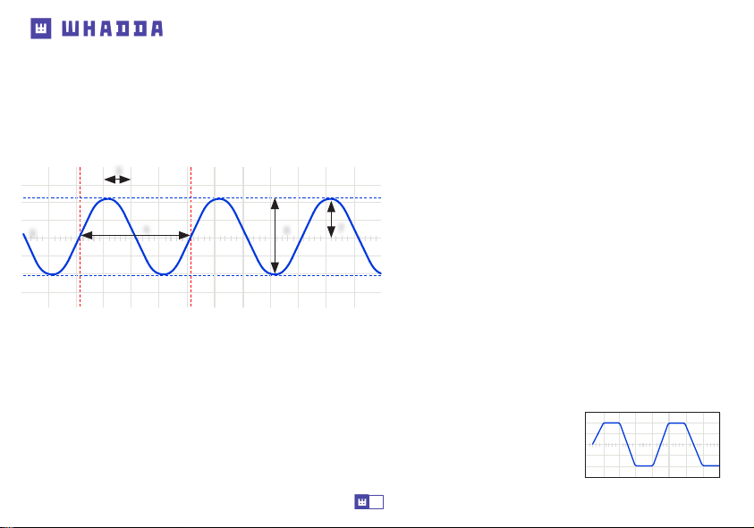
Oscilloscope terminology
OSCILLOSCOPE TERMINOLOGY
1. Volts/div: Determines how many volts the signal at the input must swing for the trace to move one division.
2. Time/div: Determines the time the trace needs to scan from the the left hand side to the right hand side of a division.
3. Division: Imaginary or visible grid on the oscilloscope screen. It helps estimating signal amplitude and period.
4. Period (T): Duration of one cycle of the AC waveform (= 1/f)
6
AC coupling: The oscilloscope only displays the AC component of a signal, any DC level is ignored.
Analog: Analog scopes use the incoming signal to deect an electron beam, which scans from left to right on the screen. The electron beam
leaves an image on the screen which represents the signal you’ve applied. Analog signals are continuously variable. See also ‘Digital’.
‘Auto-setup’ mode: The oscilloscope automatically selects a setting for Volts/div and Time/div in such a way that one or more periods
of signal are displayed correctly.
Clipping: When the ‘top’ or ‘bottom’ or both extremes of a signal are cut-o (‘clipped’), e.g. because the
signal cannot swing any further due to power supply limitations. An undesired property of ampliers that
are driven beyond their specs.
3
4
8
5. Frequency (f): The number cycles of the AC waveform per sec.
6. Trace: ‘line’ that is drawn on the screen, which represents the signal
at the input.
7. Amplitude: How far does the signal ‘swing’in a direction. Expressed
7
in mV or V. For repetitive signals: Vpeak.
8. Peak-to-peak: Dierence between most positive and most negative
swing of the signal. 2xVpeak for sinusoidal signals.
12
Page 13

Oscilloscope terminology
DC coupling: The oscilloscope displays both the AC and the DC component of a signal.
Digital: Digital scopes perform an analog to digital conversion on the incoming signal and handle all the calculations and displaying in the
digital domain. Digital signals feature only two xed levels, usually 0V and +5V. See also ‘Analog’.
Distortion: Undesired alteration of a signal due to external causes such as overloaded circuits, badly designed circuits, etc…
Noise: Undesired random addition to a signal.
Ripple: Unwanted periodic variation of a DC voltage.
Signal: Voltage applied to the input of the oscilloscope. The subject of your measurement.
Sine wave: Mathematical function that represents a smooth repetitive oscillation. The waveform shown at the start of this glossary is a
sine wave.
Spikes: Fast, short duration transients in a signal.
AC voltage: (AC: Alternating Current) With AC, the ow of the current periodically reverses, as opposed to DC, where the current ows in
one direction. An AC source does not have a polarity.
Bandwidth: Usually expressed in MHz. It is the frequency at which an applied sine wave will be displayed at an amplitude of around 70%
of its original amplitude. More expensive scopes feature a higher bandwidth. Rule of thumb: the bandwidth of an oscilloscope needs to be
at least 5 times higher than the frequency of the signal applied to the input of the scope. The EDU09 bandwidth goes up to 200KHz.
DC reference: DC measurement is always performed with respect to a ground level, so we need to dene this ground level. If you do not
set the DC reference, the readout might not be correct. In most cases, this ground level will be the center of the screen, however this is
not mandatory.
DC voltage: (DC:Direct Current) With DC, the current ows in a single direction, it does not reverse. A DC source has a polarity, (+) and (-).
13
Page 14
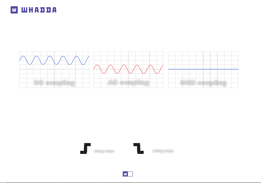
Oscilloscope terminology
Input coupling: The drawing shows typical oscilloscope input circuit. There are 3 possible settings: AC-coupling, DC coupling and GND.
With AC-coupling, a capacitor is put in series with the input signal. This capacitor blocks any DC component of the signal and passes only AC.
With DC coupling, the capacitor is bypassed and both the AC and DC component of the signal are passed. Low frequency signals (<20Hz)
should always be displayed using DC coupling. Should AC coupling be used, the internal coupling capacitor will interfere with the signal and
the displayed signal will not be correct
.
DC coupling
Sample rate: Usually expressed in samples or megasamples/second, some
digital oscilloscope ‘looks’ at the signal at the input. The more it ‘looks’, the better it is able to recreate a
on the screen. Theoretically the sample rate needs to be twice the max. frequency of the applied signal, however, for best results a
sample rate of 5 times the max. frequency is recommended. The EDU09 samplerate is 1,5Ms/s or 1,5MHz.
Sensitivity: Indicates the smallest change of the input signal that makes the trace move up or down on the screen.
Usually expressed in mV.
Slope: It determines where the scope will trigger. This can be on the rising or on the falling slope of the signal.
Vrms: The rms voltage of an AC source represents the required DC voltage to generate the same amount of heat in a resistor as
the AC source would do. For sinusoidal signals, Vrms = Vpeak / sqrt(2)
AC coupling
rising slope
GND coupling
times in
MHz. It is the number of times per second the
faithful image of the waveform
falling slope
14
Page 15
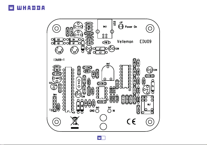
PCB
15
Page 16
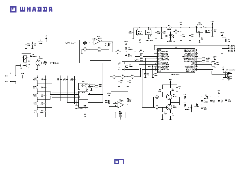
Diagram
16
Page 17
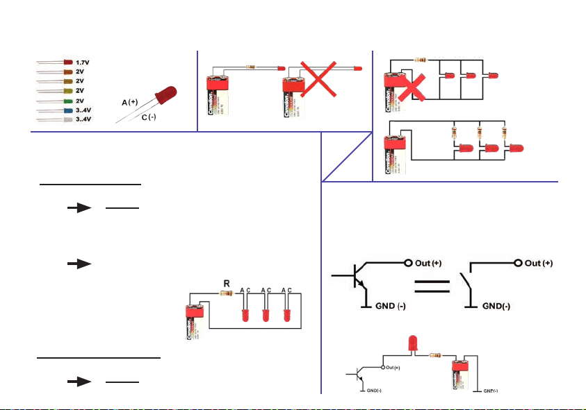
Leds and how to use them
Leds feature a specic voltage
drop, depending on type and
colour. Check the datasheet for
exact voltage drop and rated
current !
How to Calculate the series resistor:
Example: operate a red led (1.7V) on a 9Vdc source.
Required led current for full brightness: 5mA (this can be found in the datasheet of the led)
Supply voltage (V) - led voltage (V)
required current (A)
Required resistor power handling=
voltage over resistor x current passed trough resistor
(9V - 1.7V) x 0.005A = 0.036W
LEDs in series:
Example: 3 x red led (1.7V) on 9V battery
Required led current for full brightness: 5mA
(this can be found in the datasheet of the led)
9V - 1.7V
0.005A
= series resistance (ohms)
= 1460 ohm
closest value :
use a 1k5 resistor
a standard 1/4W resistor
will do the job
Never connect leds in parallel
open collector outputs
An open collector output can be compared to a switch which switches to
ground when operated
Example: How to switch an LED by means of an open collector output
Supply voltage (V) - (number of leds x led voltage (V))
required current (A)
9V - (3 x1.7V)
= 780 ohm
0.005A
= series resistance (ohms)
use an
820 ohm resistor
Page 18

whadda.com
Modications and typographical errors reserved - © Velleman Group nv. , Legen Heirweg 33 - 9890 Gavere.
WSEDU09 - 13082021
 Loading...