

Page 1
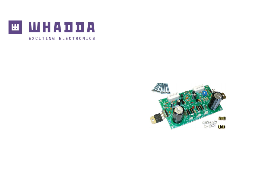
EN 200W DISCRETE POWER AMPLIFIER
WSAH8060
whadda.com
ILLUSTRATED ASSEMBLY MANUAL
Page 2

2
Specifications:
Excellent value for money
Full discrete design using Epitaxial Darlington transistors
DC supply circuit on board with LED indication
Ideal for active speaker system or sub woofer, guitar amp, home theatre systems, instruments amp….
Comes complete with transistor isolators, spacers and bolts
Overload and short circuit protection
Features:
200W music power @ 4 ohm load
100Wrms power @ 4 ohm load
70Wrms power @ 8 ohm load
Distortion: 0.02% @ 1KHz/10W
Damping factor: >800
Frequency response: 3Hz to 200KHz (-3dB)
Sensitivity: 0.6Vrms
Signal to noise ratio: 115dB
Power supply: 2 x 25-30Vac / 100 - 120VA
PCB dimensions: 107x62mm (aprx.) :
Recommended power transformer: 12030
Recommended heat-sink: HSVM100 (pre-drilled) or S44/75 (not drilled)
Features & Specifications
Page 3
3
Assembly hints
1. Assembly (Skipping this can lead to troubles ! )
Ok, so we have your attention. These hints will help you to make this project successful. Read them carefully.
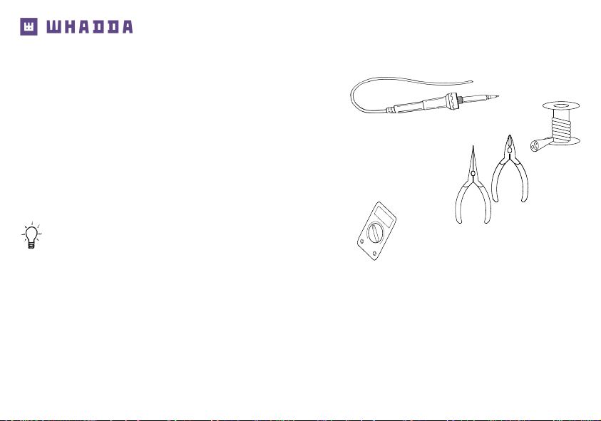
1.1 Make sure you have the right tools:
• A good quality soldering iron (25-40W) with a small tip.
• Wipe it often on a wet sponge or cloth, to keep it clean; then apply solder to the tip, to give it a wet look. This is called ‘thinning’ and will
protect the tip, and enables you to make good connections. When solder rolls off the tip, it needs cleaning.
• Thin raisin-core solder. Do not use any flux or grease.
• A diagonal cutter to trim excess wires. To avoid injury when cutting excess leads, hold the lead so they
cannot fly towards the eyes.
• Needle nose pliers, for bending leads, or to hold components in place.
• Small blade and Phillips screwdrivers. A basic range is fine.
For some projects, a basic multi-meter is required, or might be handy
1.2 Assembly Hints :
Make sure the skill level matches your experience, to avoid disappointments.
Follow the instructions carefully. Read and understand the entire step before you perform each operation.
Perform the assembly in the correct order as stated in this manual
Position all parts on the PCB (Printed Circuit Board) as shown on the drawings.
Values on the circuit diagram are subject to changes.
Values in this assembly guide are correct*
Use the check-boxes to mark your progress.
Please read the included information on safety and customer service
* Typographical inaccuracies excluded. Always look for possible last minute manual updates, indicated as ‘NOTE’ on a separate leaflet.
0.000
Page 4
4
Assembly hints
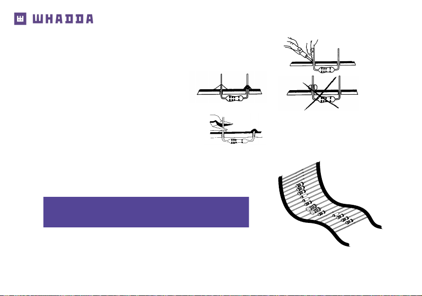
1.3 Soldering Hints :
1- Mount the component against the PCB surface and carefully solder the leads
2- Make sure the solder joints are cone-shaped and shiny
3- Trim excess leads as close as possible to the solder joint
REMOVE THEM FROM THE TAPE ONE AT A TIME !
AXIAL COMPONENTS ARE TAPED IN THE
CORRECT MOUNTING SEQUENCE !
Page 5
5
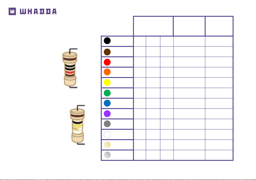
DIGITS Multiplier Tolerance
1st 2nd 3rd stripe 4th stripe
Black
0 0 0 x 1
Brown 1 1 1 x 10 1%
Red 2 2 2 x 100
Orange
3 3 3 x 1 000
Yellow 4 4 4 x 10 000
Green 5 5 5 x 100 000
Blue 6 6 6 x 1 000 000
Purple
7 7 7 -
Grey
8 8 8 -
White 9 9 9 -
Gold - - - x 0.1 5%
Silver
- - - x 0.01 10%
RESISTOR COLOR CODE
10K OHM
+/- 1%
1st digit
2nd digit
3rd digit
multiplier
tolerance
100K OHM
+/- 5%
1st digit
2nd digit
multiplier
tolerance
0.6 W
Page 6
6
Construction
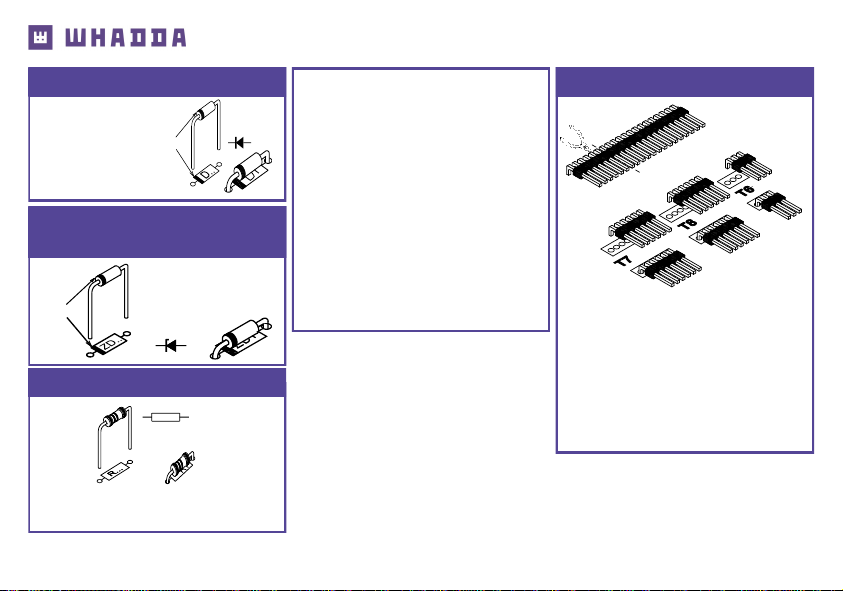
❑ D1 : 1N4148
❑ D2 : 1N4148
1. Diodes. Watch the polarity !
D...
CATHODE
❑ ZD1 : 9V1
2. Zenerdiode. Watch the
polarity !
❑ R1 : 47K (4 - 7 - 3 - B)
❑ R2 : 100 (1 - 0 - 1 - B)
3. Resistors
R...
ZD...
CATHODE
ZD...
❑ R3 : 3K3 (3 - 3 - 2 - B)
❑ R4 : 330 (3 - 3 - 1 - B)
❑ R5 : 220 (2 - 2 - 1 - B)
❑ R6 : 47 (4 - 7 - 0 - B)
❑ R7 : 680 (6 - 8 - 1 - B)
❑ R8 : 3K3 (3 - 3 - 2 - B)
❑ R9 : 3K3 (3 - 3 - 2 - B)
❑ R10 : 10 (1 - 0 - 0 - B)
❑ R11 : 3K3 (3 - 3 - 2 - B)
❑ R12 : 1K5 (1 - 5 - 2 - B)
❑ R13 : 3K3 (3 - 3 - 2 - B)
❑ R14 : 1K8 (1 - 8 - 2 - B)
❑ R15 : 1K (1 - 0 - 2 - B)
❑ R16 : 47 (4 - 7 - 0 - B)
❑ R17 : 220 (2 - 2 - 1 - B)
❑ R18 : 33K (3 - 3 - 3 - B)
Cut a piece of 3 pins (fig) of the
pin header and mount it for T6
Cut a piece of 6 pins and
mount it for T7
Cut a piece of 6 pins and
mount it for T8
4. Transistor connections
Page 7
7
Construction & connection
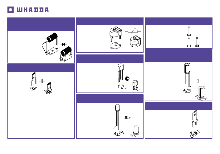
❑ C1 : 47pF (47)
❑ C2 : 47pF (47)
❑ C3 : 47pF (47)
❑ C4 : 680pF (681)
❑ C5 : 680pF (681)
❑ C6 : 47nF (473)
❑ C7 : 100nF (104)
❑ C8 : 100nF (104)
6. Capacitors.
C...
❑ LD1 : Red
9. LED. Watch the polarity!
LD...
CATHODE
❑ T1 : BC640
❑ T2 : BC640
❑ T3 : BC639
❑ T4 : BC547B
❑ T5 : BC557B
8. Transistors.
❑ RV1 : 1K
7. Trim potentiometer
RV1
❑ IN
❑ GND
10. PCB tabs.
❑ LS+
❑ LS-
❑ AC (2x)
❑ AC-0 (2x)
12. PCB terminals
SK...
❑ C9 : 10µF
❑ C10 : 100µF
❑ C11 : 470µF
11. Electrolytic Capacitors.
Watch the polarity !
C...
❑ D3 : 1N5404
❑ D4 : 1N5404
❑ D5 : 1N5404
❑ D6 : 1N5404
5. Power diodes.
Watch the polarity !
D...
CATHODE
+/-5mm
Page 8
8
Construction
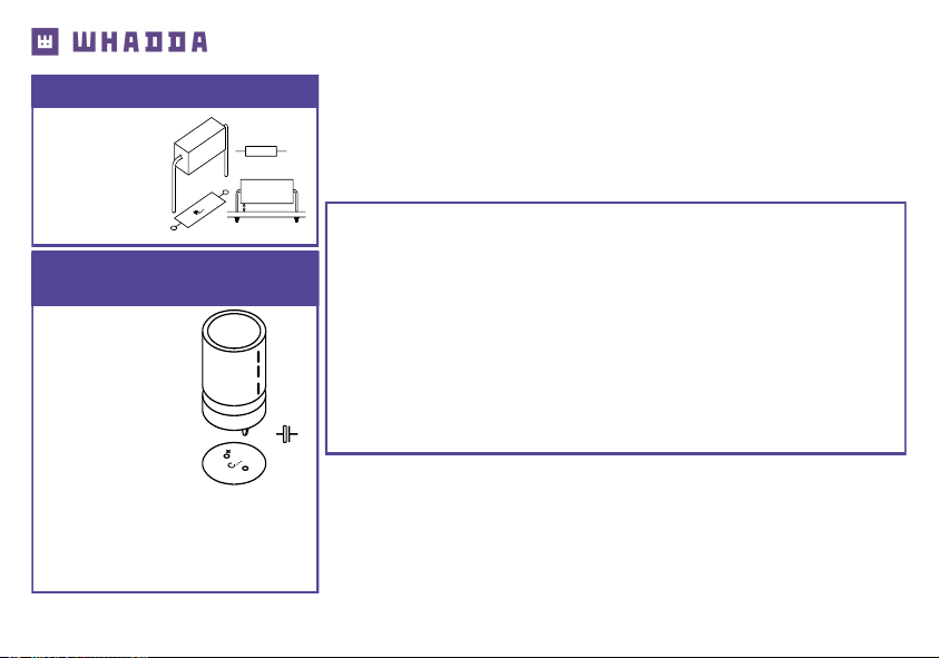
❑ R19 : 0,47
❑ R20 : 0,47
13. 5W resistors
R...
2mm
❑ C12 : 3300µF
❑ C13 : 3300µF
Hint for
tweakers :
Replace the original caps with
4700µF/50V types for even better
performance.
14. Electrolytic Capacitors.
Watch the polarity !
C...
IMPORTANT
Check the complete assembly carefully before
mounting the heat sink.
Once the heat sink is mounted, the solder-side
is no longer accessible.
Page 9
9
Final Assembly
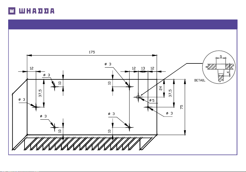
A custom pre-drilled heat sink is available from your distributor (order code HSVM100).
Any other heat sink must be able to dissipate at least 30W (1.25°C/W) (see fig.1.0).
Use the template as a drill guide.
15. Final assembly
Fig. 1.0
Page 10
10
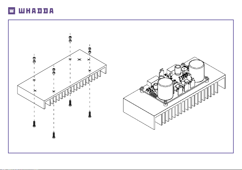
• Mount 4 bolts + 8 nuts (PCB support). (fig.2.0)
Final assembly
2 x M3 nut
M3 15mm bolt
• Slide the PCB over the 4 bolts, and fix using 4 nuts
(Fig 3.0).
Fig. 2.0
Fig. 3.0
Page 11
11
Transistor T6
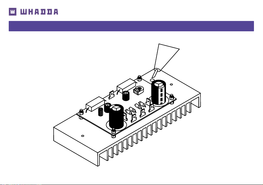
16. Mounting the transistor T6 on the heat sink:
• Apply a drop of heat conductive compound in the heat sink hole (fig. 4.0).
Fig. 4.0
Page 12
12
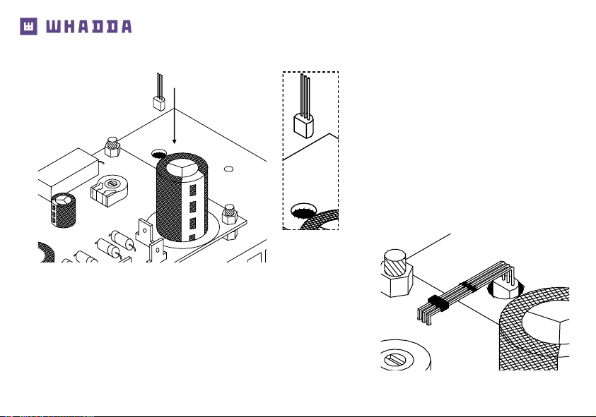
• Insert the transistor (BC547) in the hole (Fig. 5.0). Pay attention to the position of the
transistor (fig 6.0)!
• Carefully bend the leads and solder them to the connector T6, see
figure 7.0.
Fig. 5.0
Fig. 6.0
Fig. 7.0
Transistor T6
BC547
Page 13
13
Power transistors
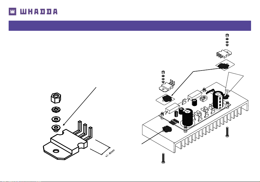
• Apply a drop of heat conductive compound on the heat sink (see fig 8.0.)
• Mount the isolation mica onto the heat sink, check the position of the hole.
Apply a drop of heat conductive compound on the mica.
• Carefully bend the leads, see fig. 9.0
• Mount the transistor on the heat sink, using a bolt, washer, lock washer
and nut.
IMPORTANT: If metal body transistors are used, a plastic
isolation washer must be applied (see 9.0.)
17. Mounting of the power transistors T7 (TIP147) and T8 (TIP142).
M3 nut
Lock washer
washer
plastic isolation
washer
Heat conductive
compound
Heat conductive
compound
M3 bolt
M3 bolt
Fig. 8.0
Fig. 9.0
Page 14
14
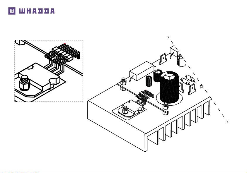
• Solder the connections of the power transistors with the pin headers, see fig. 10.
Fig. 10
Power transistors
Page 15
15
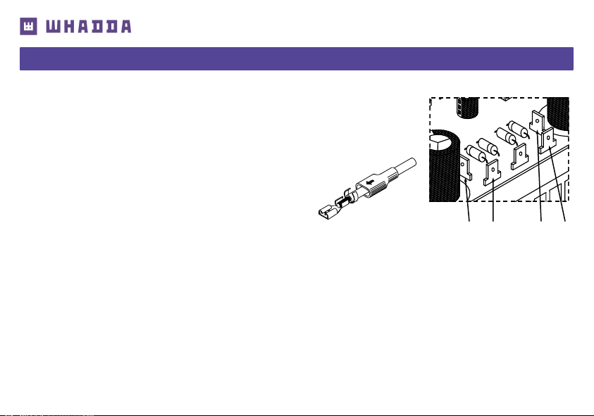
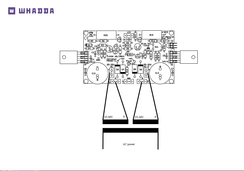
• Use a 2 x 25 to 30Vac / 100 - 120VA transformer.
• Connect the transformer to the AC power connections of the PCB.
• The Velleman transformer colour scheme is specified on the pcb.
Careful : Other brands may feature a
different scheme !
Y: yellow, R: red, B: blue, G: grey.
• Make sure to put a 1A T (slow-blow) fuse in series with the primary winding
of the transformer (see diagram).
18. Test and adjustments
Test & adjustments
Y R G B
SOLDER
Page 16
16
Test & adjustments
Page 17

17
Test & adjustments
• Turn the RV1 bias adjust trimmer fully counter clockwise (turn left) before applying power for the first time.
ADVICE: For safe first-time testing insert a 60W light bulb in series with the AC power and the transform-
er. If the light bulb lights up continuously, disconnect the transformer and check all your wiring and assembly. Reconnect the power supply. If the lamp remains off, everything is OK, replace the light bulb with
a fuse.
If the TR8040 transformer is used there is a selection of primary AC voltage :
❑ 120Vac: black / brown.
❑ 230Vac: black/orange.
IMPORTANT: Insulate the wire that is not being used.
NOTE: Two amplifiers and two transformers are required for stereo. Never attempt to run two amplifi-
ers from a single transformer!
Setting the bias:
• Connect a multimeter (lowest DC voltage range 1V or lower) over the leads of R19 (polarity is indicated on
the PCB).
• Turn on the power, the power LED should light.
• Check the multimeter, it should read 0V, adjust RV1 carefully to about 10mV (0.01V) Wait a few minutes
until the meter reading remains stable.
• Turn off the AC power. The amplifier is now ready for use.
Page 18

18
Final connection:
• The input (GND and in) can be connected directly to an audio source (pre-amp or mixing panel) or a vol-
ume control (potentiometer) can be used (see diagram).
• Connect the speaker (4 ohm or higher) to the connections LS+ and GND.
CAUTION: VOLTAGES OF ABOUT 80V ARE PRESENT. MAKE SURE TO USE A SUITABLE ENCLO-
SURE AND ISOLATE ALL AC CONNECTIONS
Test & adjustments
Page 19
19
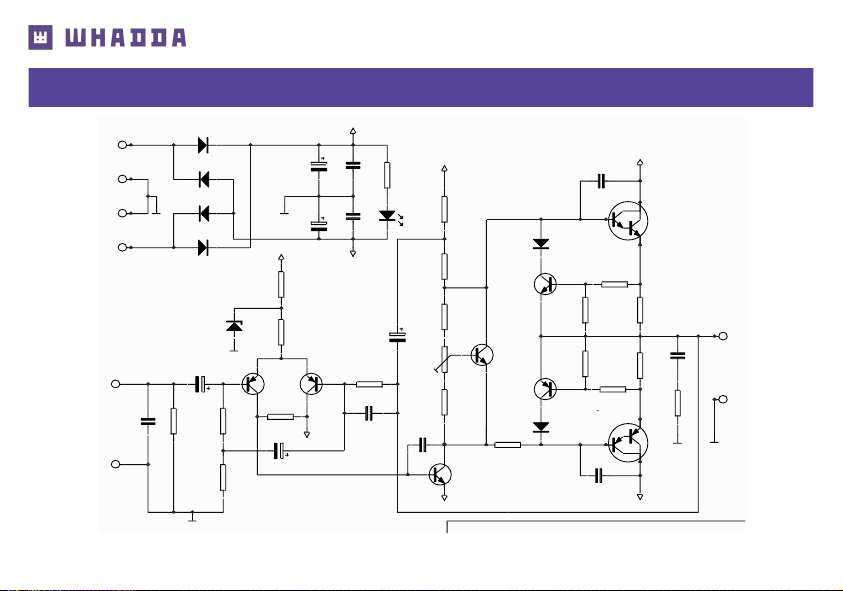
19. Diagram
Diagram
1
2
3
4
Title
GND
+40V
GND
1N54 04
D6
1N54 04
D3
1N54 04
D5
1N54 04
D4
AC-0
SK6
AC-0
SK5
AC
SK3
LS+
SK8
LS-
SK7
4700 µ/50V
C13
4700 µ/50V
C12
AC
SK4
-40V
100n F
C7
100n F
C8
47nF
C6
47p
C2
47p
C1
680p
C4
47p
C3
680p
C5
10µF
C9
33K
R18
47K
R1
3K3
R11
3K3
R9
3K3
R3
10
R10
LED3 RL
LD1
TIP1 42
T8
TIP1 47
T7
GND
SK1
In
SK2
0.47 / 5W
R19
0.47 / 5W
R20
BC54 7
T6
BC54 7
T4
BC55 7
T5
BC63 9
T3
330R
R4
100R
R2
1K8
R14
680R
R7
3K3
R8
500R
RV1
ZB9 V1
ZD1
+40V
+40V
+40V
GND
GND
GND
GND
-40V
-40V
-40V
470µ/ 16V
C11
3K3
R13
1K5
R12
47R
R6
220R
R17
47R
R16
1N41 48
D1
1N41 48
D2
220R
R5
100µ/ 50V
C10
Bias curre nt (c old)
10-15 mV over R19
Bias adj.
BC64 0
T1
BC64 0
T2
1K
R15
Page 20

Modifications and typographical errors reserved. © Velleman Group nv, Legen Heirweg 33 - 9890 Gavere (België)
WSAH8060 - 09082021
whadda.com
 Loading...