

Page 1

Osmo
DEMINERALIZER
USER MANUAL
Dear Owner,
Thank you for purchasing our demineralizer Osmo.
The manufacturer is pleased to provide information concerning the use of this equipment herewith.
We remind you that in order to use the demineralizer correctly, it is necessary to read this manual carefully.
All our products comply with the current safety norms and do not involve any risk for the operator when
used according to the instructions provided.
Whilst wishing you every success in your work, please note that the reproduction of this manual is illegal
and that, due to continuous research and technological development, the equipment specifications could
change without prior notice.
W&H
STERILIZATION
S.r.l.
Osmo
1
Page 2

TABLE OF CONTENTS
INTRODUCTION..............................................................................................................................................3
GENERAL WARNINGS................................................................................................................................3
RESIN–SECURITY PRECAUTIONS............................................................................................................4
ACTIVE CARBON FILTERS – SAFETY WARNINGS*................................................................................4
INFORMATION ON THE WARRANTY.........................................................................................................5
PACKAGE CONTENTS...................................................................................................................................6
GENERAL NOTES ON DELIVERY..............................................................................................................6
PACKAGE SIZE AND WEIGHT....................................................................................................................6
DELIVERY CONTENT..................................................................................................................................7
INSTALLATION AND USE OF THE DEMINERALIZER.................................................................................8
SYMBOLS ON THE NAMEPLATE...............................................................................................................8
SYSTEM COMPONENTS ............................................................................................................................8
PRELIMINARY INSTALLATION INSTRUCTIONS.......................................................................................9
INSTALLATION...........................................................................................................................................10
PRIMING.....................................................................................................................................................12
EXAMPLES OF USAGE.............................................................................................................................13
USE AND OPERATION OF THE DEMINERALIZER....................................................................................14
PRECAUTIONS TO AVOID WATER CONTAMINATION..........................................................................14
IDENTIFICATION OF THE CARTRIDGES.................................................................................................14
REPLACEMENT OF FILTER CARTRIDGES.............................................................................................15
REPLACEMENT OF THE OSMOTIC MEMBRANE...................................................................................16
MAINTENANCE.............................................................................................................................................17
EXTERNAL CLEANING..............................................................................................................................17
MAINTENANCE OF THE WATER BLOCK® AND ONE-WAY VALVE.......................................................17
SPARE PARTS...........................................................................................................................................18
TECHNICAL SPECIFICATIONS....................................................................................................................20
MAINTENANCE ISTRUCTIONS FOR THE SAFETY VALVE (WATER BLOCK®)......................................21
2
Osmo
Page 3

INTRODUCTION
This manual provides instructions for:
- Safe and efficient operation of the equipment
- The correct installation
- Continuous and scheduled maintenance.
• The dimensions mentioned in this manual are subject to change without notice.
• Drawings and any other documents delivered with the equipment belong to the manufacturer, who
reserves all rights; they cannot be made available to third parties.
• The reproduction, either total or in part, of the texts and the illustrations in this manual is forbidden.
Note: If the Osmo demineralizer is used to supply sterilizers with demineralized water, it is imperative to
monitor the water quality. If the supplied sterilizers do not feature a water conductivity sensor to
monitor the water quality, we recommend using the manual water conductivity meter Primo 5.
GENERAL WARNINGS
• The equipment should be used in compliance with the procedures described in the manual and never
for purposes other than those detailed in the manual.
• The user is responsible for installing, operating and servicing the equipment in accordance with the
instructions listed in this manual.
• Only use genuine manufacturer resin cartridges dedicated for this product.
• Do not drink the water produced by Osmo.
• Do not block or crush the inlet or outlet pipes of the equipment or the sterilizer.
• If the spray gun is not used (manual filling) we recommend closing the spiral tube’s connecting
tap.
• If the equipment is not operated according to the instructions in this manual or is not properly
maintained, the manufacturer cannot be held responsible for any fault, damage or malfunctioning of the
equipment.
• If the water shows high quantities of turbidity, chlorine, iron and manganese, silicon, or a level of TDS
(Total Dissolved Solids) above 2,000 ppm, the effectiveness and above all the life-span of the osmotic
membrane will be significantly affected.
• Do not use the device with water over 20°C
• If the device is not used continuously it may emanate unpleasant smells.
Intended use: This manual is an integral part of the product and must be kept close to the equipment for
easy and quick reference. The equipment is to be used only for the purpose for which it is designed.
Osmo: Equipment designed for the demineralization of tap water
Osmo
3
Page 4

RESIN–SECURITY PRECAUTIONS
Contact Hazards
Eye contact Irritation of the eyes (R36).
Skin contact Slight irritation of the skin.
First Aid procedures
Eye contact Flush immediately with large amounts of water and remove the resin
Skin contact Take off the contaminated clothes.
Precautions in case resin material is spilled
Precautions for People Keep people away from the area of spillage.
Cleaning methods Sweep the floor and transfer the resin beads to a plastic container for
The used product is a special non hazardous waste.
The product must be disposed of in accordance with current local, regional and national regulations.
The CER number for saturated or used ion-exchange resins used for the production of drinking or service water is:
19 09 05.
beads.
Remove the resin beads and flush the contaminated area with water.
Resin beads on the floor may cause it to be slippery. Take care not to
slip.
collection or disposal according to the appropriate guidelines.
Notes for disposal
ACTIVE CARBON FILTERS – SAFETY WARNINGS*
Contact hazards
Eye contact Possible temporary irritation due to the abrasive effect of the granules.
Skin contact Possible temporary irritation due to the abrasive effect of the granules.
First aid procedures
Skin contact The product cannot be absorbed by the skin. Can provoke dehydration, or
Contatto gli occhi Do not rub the eyes.
Precautions in case of accidental spillage
Precautions for People Keep people away from the area of spillage.
Cleaning methods Collect using mechanical methods or a vacuum cleaner so as to avoid the
Notes for disposal
If the product is unused: normal disposal is allowed
If the product has been (with presence of absorbed substances): method of disposal varies according to the nature of
the absorbed substance and to the current applicable national or regional norms. The number is CER 19 09 04.
* extracted from the safety data sheet supplied by the manufacturer. For further information, please request the safety data sheet
directly from the manufacturer of distributor of the product.
mild irritation due to the abrasive effect of the granules.
Remove contaminated clothes and wash skin with water and soap.
Consult your doctor should symptoms of dehydration appear.
Flush immediately with large amounts of water, and keep eyes open for at
least 15 minutes (so as to eliminate dust). If necessary consult your
optician.
Granules on the floor may cause it to be slippery. Take care not to slip..
formation of dust. Use appliances that don’t create electric charges or
sparks.
4
Osmo
Page 5

INFORMATION ON THE WARRANTY
The manufacturer guarantees the quality of your product, if used in accordance with the instructions
described in this manual, for a period of 12 months for mechanical components.
The warranty starts from the date of delivery to the customer, which must be proven by returning the
warranty form duly filled in and signed.
In the case of disputes, the date on the delivery note relating to the equipment serial number will be valid.
The warranty does not cover defects or damage caused by:
• Incorrect installation
• Inadequate maintenance
• Tampering or unauthorized modifications
• Incorrect use of the equipment
• Non-compliance with the instructions included in this manual
The replacement of equipment or the extension of the warranty period because of breakdown is excluded.
Repair under warranty is carried out at the discretion of the manufacturer and does not include packing and
shipment costs.
Osmo
5
Page 6

PACKAGE CONTENTS
GENERAL NOTES ON DELIVERY
Upon delivery of the equipment, check the condition of the package and keep it in case of future needs.
Open the package and check that:
- the contents correspond to the delivery note
- there is no evidence of any damage.
In the event of damage or missing items, inform the carrier and the supplier immediately.
PACKAGE SIZE AND WEIGHT
Gross weight: 18 kg
Dimensions (mm):
6
Osmo
Page 7

DELIVERY CONTENT
Figure 1 – Delivery Content
Item Description
1 Complete osmotic subset with mounting brackets composed of: 3 filter cartridges, 1 osmotic
membrane, 1 pump, 1 one-way valve, 1 pressure switch and a variety of internal and external
connecting tubes and spiral tube with spray gun.
2 9 litre storage tank with a tap ( theoretic volume 13/19 litres - actual volume 9/10 litres)
3 Power Supply transformer 240Vac
/ 24 Vdc
4 Water Block® valve with filter and setting key with one-way valve and hydraulic system tube (5m,
Ø1/4”)
5 Special key for cartridge holders
6 drain tube installation kit
7 Dowels and screws for fixing the system to a wall
8 Drain tube for carbon block cartridge
9 Warranty certificate , CE declaration of conformity and user manual
Osmo
7
Page 8
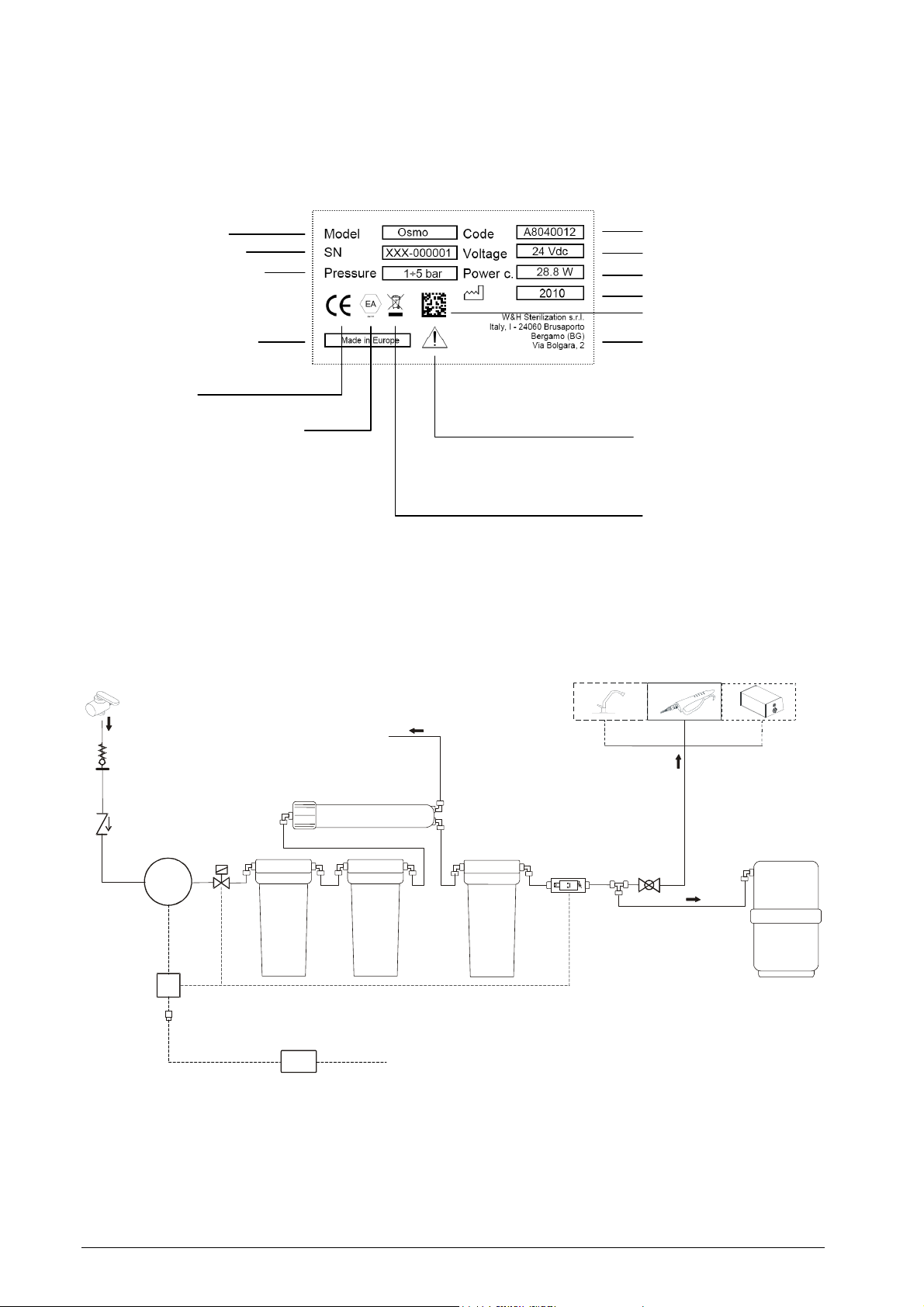
INSTALLATION AND USE OF THE DEMINERALIZER
240Vac 24Vdc
EV
Recycling
SYMBOLS ON THE NAMEPLATE
Model name
Serial number
Working pressure
Country of manufacture
CE label
The equipment is fitted with a
protective mechanical device
allowing only one-way water
flow; in accordance with EN
1717
SYSTEM COMPONENTS
Inlet tap
Water Block
valve
One-way valve
Drain water
outlet
Membrane
Product code
Working voltage
Power consumption
Year
Serial number datamatrix
Manufacturer
Read the manual carefully
symbol
Tap
(optional)
Spray
gun
SAT
(optional)
Pump
Carbon
Block filter
Power supply unit
Figure 2 – Composition of the device
8
Pressure
control switch
Resin filter
cartridge
Storage
tank
Osmo
Page 9
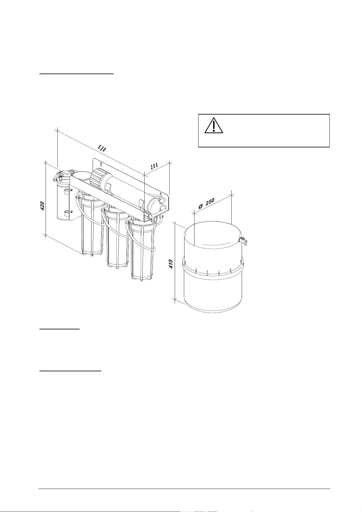
Figure 3
–
Overall dimensions
PRELIMINARY INSTALLATION INSTRUCTIONS
Wall-mounted installation
The water demineralizer should be fitted in a vertical position either beneath a sink or in a cabinet. For
mounting, use the supplied dowels and screws. Install on the wall leaving a space of at least 10 cm from
the floor or the bottom surface so that the cartridge holders can be dismantled.
When the storage tank is full of
water, it weighs approximately
13kg. Check that the work surface
supports this weight.
Power Supply
The unit is supplied with 240 Vac by means of a transformer which complies with the applicable electrical
safety requirements of the Standards Institutes.
The maximum power absorbed is 40W.
Hydraulic installation
Drain Install a drain nearby to dispose the wastewater discarded by the osmotic membrane
(max 1.5m)
WB Valve The safety valve (Water Block®) is fitted with a special one-way valve which prevents the
return of water into the hydraulic system and possible consequent contamination. For
this purpose, the WB valve must be fitted in a vertical position (refer to the
instructions at the end of this manual).
Charge The installation of the product with incoming water pressure above 3 bars, can
drastically reduce the lifespan of all the cartridges and especially of the osmotic
membrane. If this is the case, the installation of a reducer to bring the pressure to less
than 3 bars is recommended.
Osmo
9
Page 10
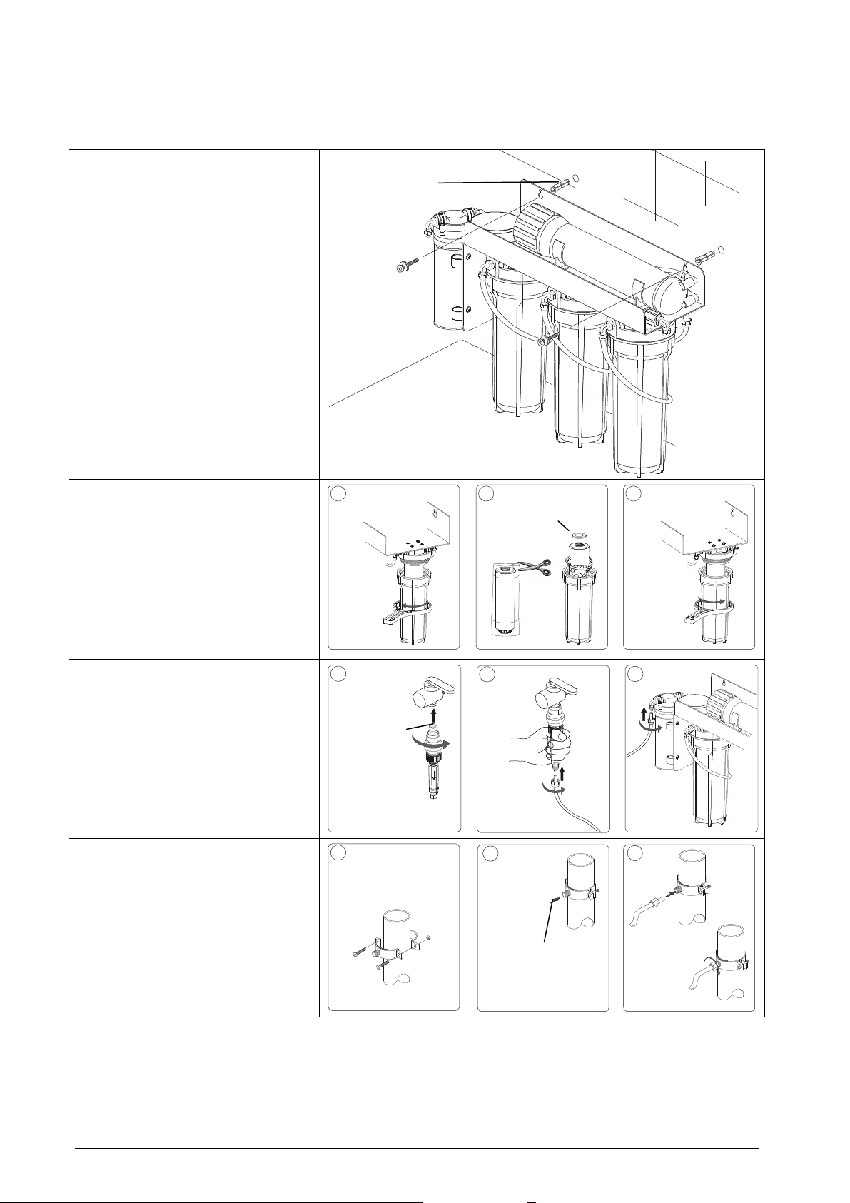
INSTALLATION
C
C
C
Ø
6mm
Gaskets and
Install the osmotic group using the
supplied dowels and screws
Unscrew the cartridge holders.
Remove the cartridges and take off
the wrapping (resin and carbon
block cartridges). Reposition the
cartridges in the holder taking care
of the centring rings, the gaskets
and O-rings.
Tighten all the holders.
A B
O-Rings
Connect the water block group and
one-way valve to the water network
tap.
Insert the tube into the fitting and
tighten with a ring nut.
Connect the tube to the pump’s
inlet fitting and tighten with a ring
nut.
Mount the brackets from the
assembling kit on the drain tube.
Pierce the drain tube with a bit Ø
6mm.
Insert the
the back of the osmotic membrane
and tighten with a ring nut.
black drain tube
from
A
Check that
the filter is
present
A
B
B
Pierce
Ø6mm
10
Osmo
Page 11
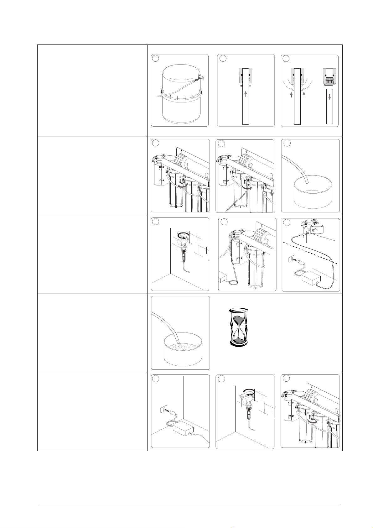
C
B
C
C
B
C
Connect the
fitting from the osmotic group to the
storage tank.
This is a quick-connector fitting:
insert the tube until it hits the back of
the fitting and pull slightly to check it
is correctly inserted.
To take the tube out of the fitting,
press the fitting ring with your fingers
and pull out the tube.
Disconnect the tube from the outlet
fitting of the carbon block cartridge
head (middle holder).
Insert the supplied
tube
on the fitting and tighten with a
ring nut.
Position the tube in a draining sink
or a collecting basin.
white tube
red draining
from the T
A B
A
Open the devices tap.
Connect the transformer’s 24V
outlet wire to the osmotic group’s
power supply connector.
Insert the plug into a plug hole.
Leave the water that comes out of
the active carbon filter to drain until
the water has no more black bits.
Remove the plug form the plughole.
Close the device tap
Reset the original connection on the
carbon block’s cartridge head
(disconnect the red tube, reconnect
the white tube and tighten with the
ring-nut ).
A
5÷15 min
A
B
B
Osmo
11
Page 12
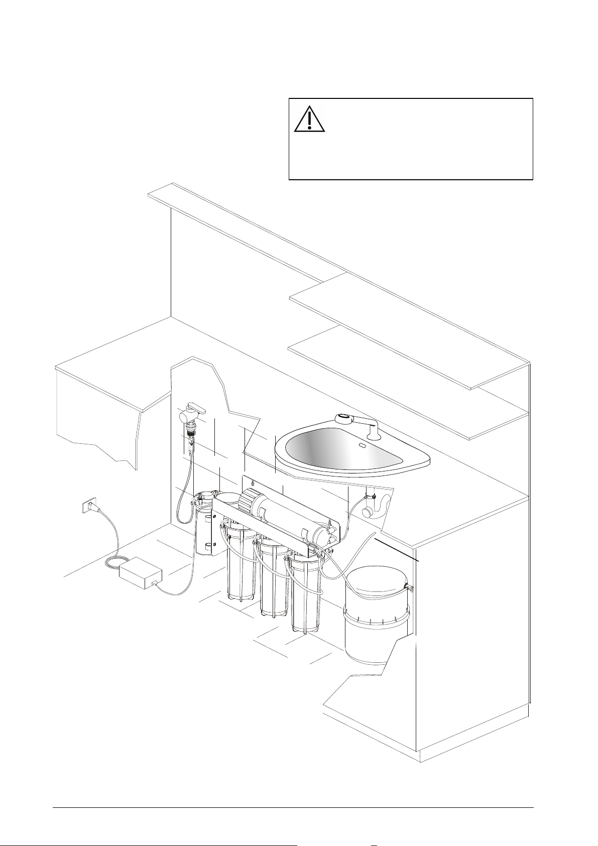
PRIMING
• Open the water network tap
•
Insert the plug into a plug-hole
ATTENTION
After setting up the system, it takes 5
minutes to produce demineralized water
It takes approx. 140 minutes to
completely fill up the system (including
the storage tank)
Figure 4 – Example of installation
12
Connection to:
Spray gun
tap (optional)
SAT (optional)
Osmo
Page 13
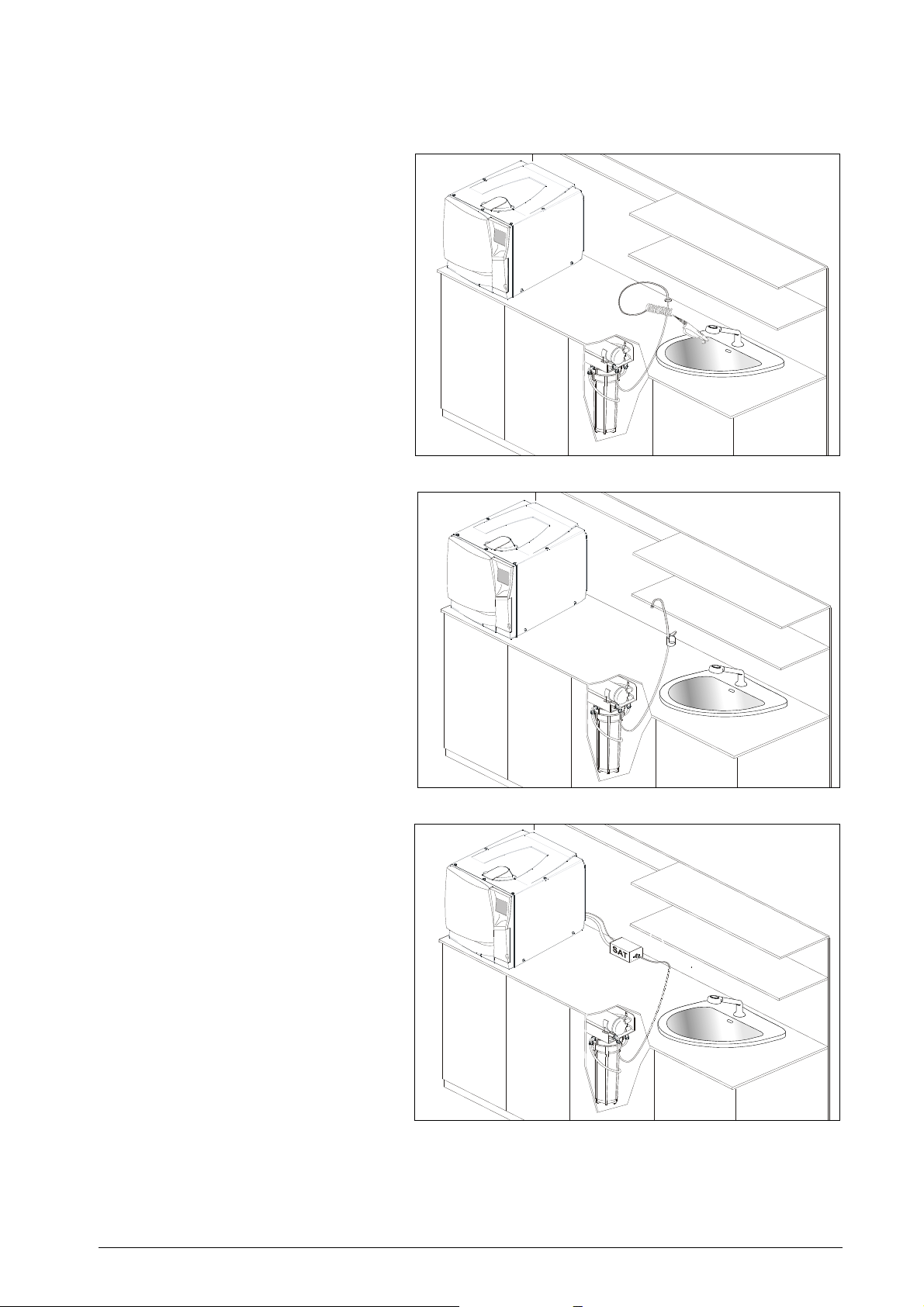
EXAMPLES OF USAGE
Manual use with spray gun
(standard) for manual filling of
the sterilizer tank and washing
of instruments
Manual usage with tap service
tank
Automatic use to fill the
sterilizer using the SAT (option)
Figure 5 – Possible uses of the device
Osmo
13
Page 14
USE AND OPERATION OF THE DEMINERALIZER
USE OF DEMINERALIZER
Once the system has been correctly installed and connected, the demineralizer is able to immediately
supply purified and demineralized water.
If the demineralized water is used to run a sterilizer, you have the option of manually filling the sterilizer
tank with the use of the water gun, or have it filled automatically by using an external filling device (e.g. Sat)
connected to the Osmo device.
The quantity of water produced by the cartridges depends on the quality and hardness of the city water
supply in the area where you live.
The average time it takes to fill the storage tank is approximately 140 minutes (with the pressure control
switch set to 3 bar).
PRECAUTIONS TO AVOID WATER CONTAMINATION
CAUTION
In accordance with subsection 4.5 of EN1717, in order to avoid water quality degradation and
bacterial growth due to a tailback of water in the tubings, the entire system must be drained
before leaving it unused for a longer period of time.
WARNING
Re-using the system after a long period of non-use
To restart the system when it hasn’t been used for a long time or after the system has been
emptied, water needs to circulate round the entire hydraulic circuit and the water collected in the
circuit needs to be drained for a few minutes ( see chapter installation, points 6-9).
It is also recommended not to leave the storage tank filled with demineralised water for a long
period of time.
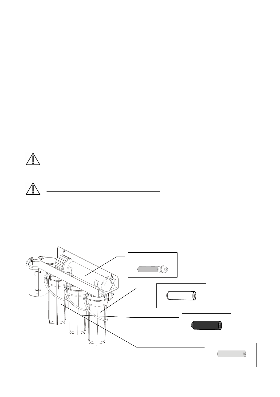
IDENTIFICATION OF THE CARTRIDGES
Osmotic membrane
14
Resin filter
Active carbon filter
Mechanical filter
Osmo
Page 15
REPLACEMENT OF FILTER CARTRIDGES
Only use genuine filter cartridges as they have been specifically designed for this product.
The need to replace cartridges depends largely on the operating conditions and, above all, on the quality of
the city water in your area. Annual filter cartridge replacement is recommended for average use.
Debris Cartridge 1µm
Complete Kit
Intermediate
Kit
Carbon Cartridge
Resin Cartridge
Osmotic membrane
Notes:
• Using the intermediate kit maintains the life-span and performance of the osmotic membrane.
• If the water has a conductivity value of over 15 µS after the intermediate kit has been replaced, also
replace the osmotic membrane
• All the cartridges can vary slightly, which in combination with unfavourable operational conditions (e.g.
high temperature, high presence of chemical particles in the water supply, high pressure) can cause a
high reduction in the performance of the product.
• In the event of unexpected contamination of the water coming into the system (for example the
presence of soil), all the cartridges can get damaged. Replace the intermediate kit and check if the
osmotic membrane also needs changing.
• The installation of the product with incoming water pressure above 3 bars, can drastically reduce the
lifespan of all the cartridges and especially of the osmotic membrane. If this is the case, the
installation of a reducer to bring the pressure to less than 3 bars is suggested.
To replace cartridges follow these steps:
1. Disconnect the power supply
2. Close the tap water inlet valve and the storage tank valve
3. Release the water pressure with the use of the water gun (or tap, if connected) and/or disconnect the
tubing leading to an external automatic filling device (e.g. Sat).
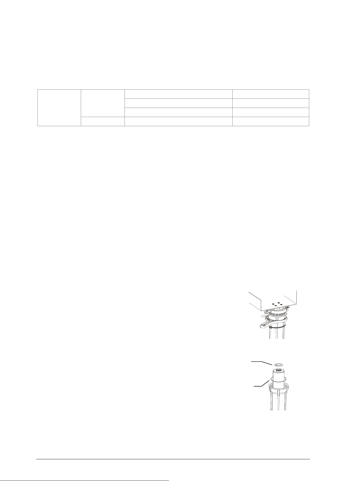
4. Unscrew the cartridge holder counter-clockwise with the use of
the supplied special tool.
5. Remove used cartridges, remove and clean the centring
rings, replace the cartridges using the rings. Make sure to
Securing
bracket
insert the cartridge in the correct holder ( if it says UP.
place the cartridge with the writing at the top).
O-R
3/6 months
3/6 months
3/6 months
2 years
Osmo
15
Page 16
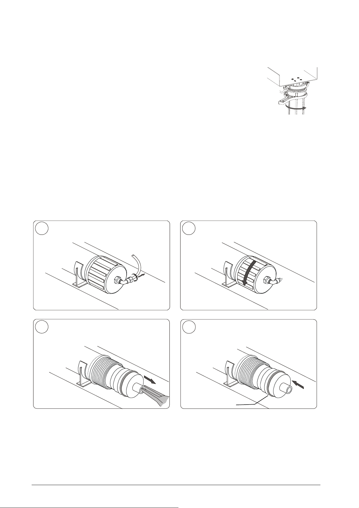
2
4
making
6. Retighten the cartridge holders by hand, taking care to
correctly position the gaskets and o-rings. Tighten the
cartridge holders with the use of the special tool.
7. Follow steps 6 to 9 in the “Installation” section.
8. Slowly reopen the hydraulic circuit tap.
REPLACEMENT OF THE OSMOTIC MEMBRANE
The service life of an osmotic membrane is normally over 2 years (depending on the quality of the city
water in your area) but the use in unsuitable conditions can drastically reduce this.
In order to replace the membrane, first unplug the power supply and close the water inlet and the storage
tank valve. Proceed as shown in the images below.
1
3
Unlock the coupling ring and remove the
tubing.
Extract the membrane with the help of
pliers.
Unscrew the cap counter-clockwise.
Insert the new membrane completely,
sure that the gasket is positioned correctly. Retighten the cap and connect the tubing.
Gasket
Figure 6 – Membrane replacement
After membrane replacement, the system needs to be primed! Refer to chapter “Priming” for further
instructions.
16
Osmo
Page 17

MAINTENANCE
EXTERNAL CLEANING
Clean with a damp cloth using non-abrasive and non-corrosive detergents (neutral pH value).
MAINTENANCE OF THE WATER BLOCK® AND ONE-WAY VALVE
Depending on the city water quality in your area and the frequency of use of the equipment, the valve inlet
filter should be regularly cleaned as explained in the instruction leaflet attached to the end of this manual.
CAUTION
Regular control of the Water Block and one-way valve
To ensure compliance with subsection 4.6 of EN1717, have the Water Block and the one-way
valve checked at least once a year; in case a sterilizer is attached to the system, this could be
done during the scheduled maintenance visits for the sterilizer.
It is further recommended to check all related devices fitted to the sterilizer to ensure that the
hydraulic connection between demineralizer and sterilizer corresponds to category 2, in
accordance with EN 1717.
WARNING
The Water Block serves as an anti-flooding device. Blocking only takes place if there is
considerable leakage (such as a cut in the tube between the Water Block and the demineralizer).
Blocking does not take place if there is a small leak in the product’s hydraulic system.
Osmo
17
Page 18
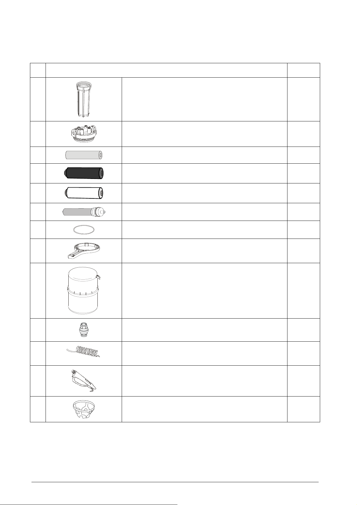
SPARE PARTS
Ref.
1
2
3
4
5
6
7
Description Code
CARTRIDGE HOLDER A812103X
FILTER HEAD A813005X
DEBRIS CARTRIDGE CPE 1µM A813015X
“CARBON BLOCK” CARTRIDGE A813016X
RESIN CARTRIDGE A813017X
OSMOTIC MEMBRANE 75 GPM, 95-98% REJECTION A813018X
O-RING A813014X
8
9
10
11
12
13
PLASTIC KEY FOR CARTRIDGE HOLDER A812101X
STORAGE TANK INCLUDING TAP A813007X
WATER BLOCK® VALVE (INCLUDING FILTER AND
SETTING KEY)
SPIRAL TUBE ¼” A812105X
A812005X
WATER GUN A812106X
CENTERING RING A813006X
18
Osmo
Page 19
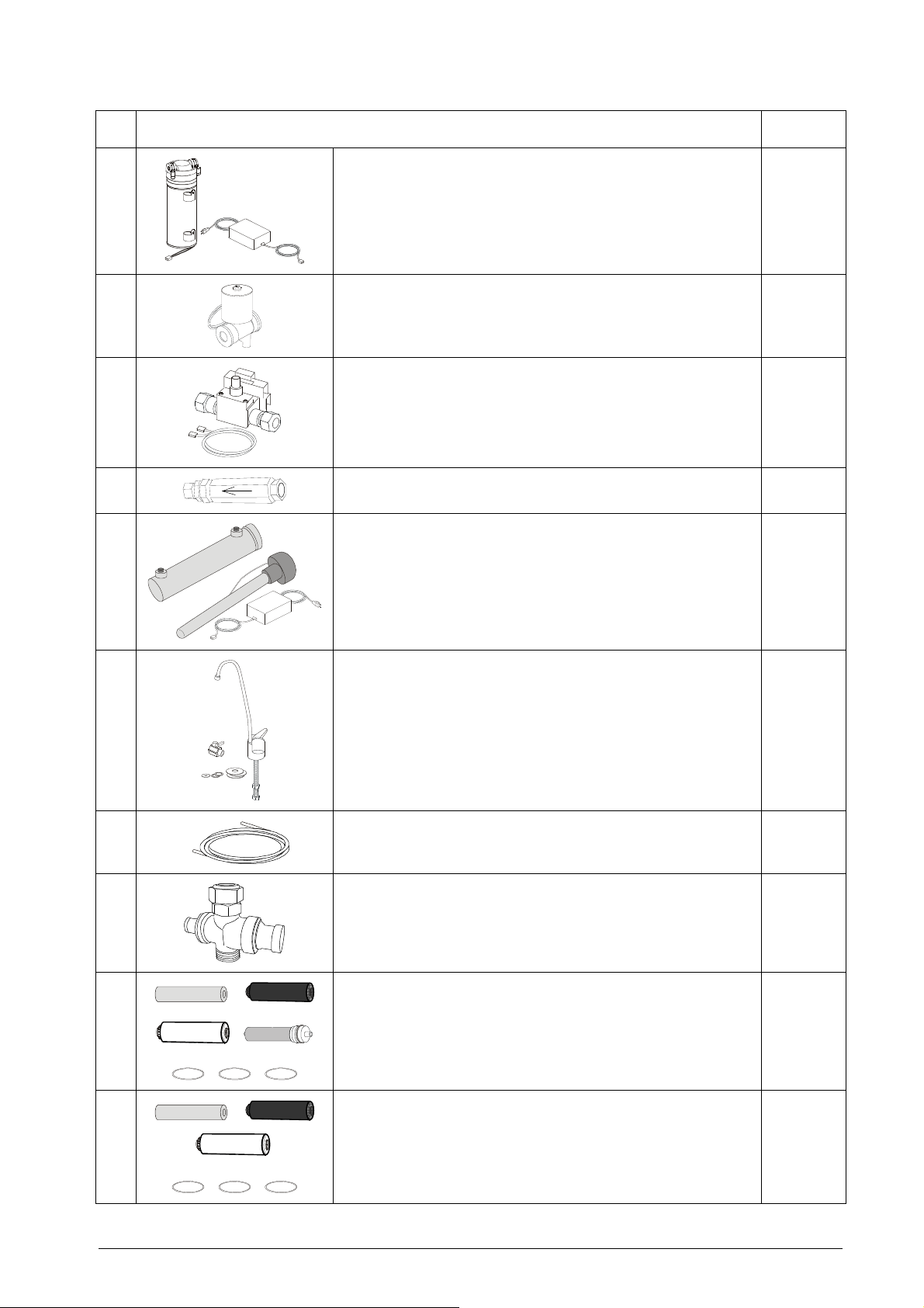
Ref.
14
15
16
17
Description Code
PUMP WITH TRANSFORMER 24Vdc A813024X
ELECTRIC-VALVE 24VDC U382016X
MANOSTAT AND WIRING KIT A813011X
ONE-WAY VALVE A812116X
18
19
20
21
22
UV KIT A813012X
KIT WATER TAP A813013X
WATER PIPE (5 m, Ø 6.35 mm) A813020X
PRESSURE REDUCER ¾” X ¾” 3 BAR A813025X
CATRIDGE KIT COMPLETE
(REF. 3+ 4 + 5+ 6 + 7x3)
A813010X
23
CARTRIDGE KIT INTERMEDIATE
(REF. 3 + 4+ 5 + 7x3)
A813019X
Osmo
19
Page 20

TECHNICAL SPECIFICATIONS
Operating temperature
Storage temperature
Size
Weight with cartridges (empty storage tank) 11 Kg
Use interior
Pollution degree 2
IP 21
Weight of the storage tank 3,5 kg
Tank - nominal volume 19 liters
Tank - storable volume ca. 9 liters
Electric power supply
Max. absorbed power 40 W
+5°C ÷ +30°C
+5°C ÷ +35°C
Protect from sunlight or other sources of heat
520x420x200 mm
100-240 VAC, 50/60 Hz, 1.0A
( with separate voltage transformer)
Class of insulation III
Tap water pressure
Quantity of produced water with conductibility <
15µS1
minim 1 bar (14,7 psi)
maximum 5 bar (73,5 psi)
10,000 liters
1
T
est conditions: T=25°C, tap water quality 450 µS an d water pressure of 3 bar; with continuous flow;
20
Osmo
Page 21
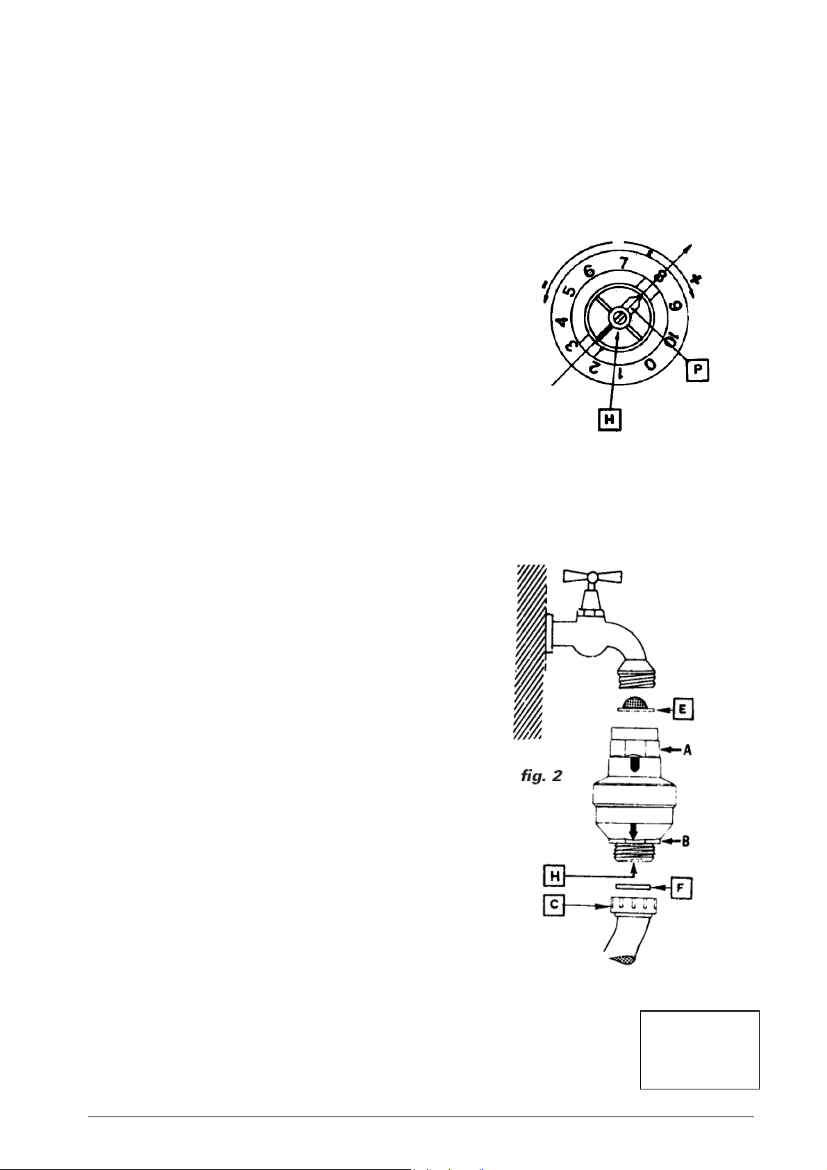
Fig. 1
MAINTENANCE ISTRUCTIONS FOR THE SAFETY VALVE
(WATER BLOCK®)
WATER BLOCK (WB) SAFETY VALVE
Indispensable device for washing machines, dishwashers and demineralizers as, under the conditions defined in the technical
features herewith described, it prevents a flow of water greater than the one for which it has been set by the adjustment
pointer. This avoids continuous leaking. The Water Block also has a particular non-return valve (antipollution). The device
should be installed vertically (see fig. 2) and following the instructions carefully.
TECHNICAL FEATURES
-
Burst pressure: 500 N/cm²
-
Max. static pressure: 100 N/cm²
-
Max. controllable volume: about 50 lt.
-
Min. operating capacity: 2 lt/min.
-
Max. operating capacity: 30 lt/min
-
Max. water temperature: 70° C
USER INSTRUCTIONS
WATER BLOCK should be installed between the tap and the supply hose of the
demineralizer (fig. 2). Using the enclosed plastic key, turn pointer ‘P’ (fig. 1)
anticlockwise to the required setting (example, position 1,5).
CAUTION:
For use on other fixtures, set the pointer to a position suitable for that particular application, considering that each number on
the scale corresponds to a controlled volume of approx. 4-6 litres.
In case of installation on fixtures which foresee dispensing of drinking water for alimentary use it is advisable to let flow at least
10 litres of water inside the device before the connection, so as remove eventual impurities banked during the storage.
INSTALLATION
1. Manually screw the WB to the tap having suitable thread (3/4” gas),
inserting the filter ‘E’ with its convex side facing upwards (fig. 2). The
WB will not operate properly if the filter is not installed correctly. If the
WB is tightened or loosened with the aid of a wrench, the same must
be applied to the appropriately octagonally shaped part of the housing
‘A’.
2. Screw the supply hose ‘C’ to the lower end of the WB. If the supply
hose is equipped with a filter, the latter must be substituted by a flat
rubber washer ‘F’. If the said hose has to be tightened or loosened with
the aid of a wrench, the same must be applied to the appropriately
octagonally shaped part of the WB housing ‘B’ so as to hold it firmly
while performing this operation.
If a failure occurs causing a continuous water leak, the WB will shut off
when the volume of water flowing through equals the amount to which it
was previously set with the pointer ‘P’.
To reset the Water Block again after it has shut off, turn the tap off and
carry out the necessary repair work. Remove the supply hose ‘C’ from
the Water Block and press the coloured plunger ‘H’ which is located
inside the lower housing of the device itself (fig. 1). It may be difficult to
press this plunger if there is high pressure at the inlet side of the WB. In
this case, slacken the device from the tap: the plunger ‘H’ can then be
pressed with ease. Repeat the operation as described in the section
headed ‘Installation’.
CAUTION:
To avoid any possible damage that may be caused by water freezing inside
the WB after its installation, the ambient temperature should never be below
2° C. We decline all responsibility deriving from th e incorrect use of the WB
or from its use for applications and/or solutions not expressly foreseen by the
above instructions.
MAINTENANCE:
Depending on the conditions and frequency of usage of the water block, it is recommended to
clean out the inlet filter ‘E’ periodically and to replace the seal ‘F’ .We reserve the right to modify any
features without prior notice.
Produced by
ELTEK s.p.a.
Tel. 0142 335511
Fax 0142 335555
15033 Casale Monf. (Italy)
[email protected]
Osmo
21
 Loading...