


Water Steam Sterilizer
LISA
MB17/22
201 10
AEN REV. 9
User Manual


1
User manual
SUMMARY
1. UNPACKING
1.1. Unpacking the sterilizer
1.2. Unpacking the accessories
2. SET-UP
2.1. Installation
2.2. Electricity supply
2.3. Printer connection (optional)
3. DESCRIPTION
3.1. Front view of the sterilizer
3.2. Rear view of the sterilizer
4. USE
4.1. Main menu
4.2. Description of the water tank
4.3. Filling of the main water tank
4.4. Draining of the used water tank
4.5. Programming
4.5.1. Selecting a language
4.5.2. Programming the name of the doctor / surgery
4.5.3. Programming the date and time
4.5.4. Programming the printer
4.5.5. Adjusting the brightness of the touch screen
4.5.6. Programming the stand-by mode
4.5.7. Maintenance program
4.5.8. Service program
4.6. CYCLE SELECTION
4.6.1. Cycle table
4.6.2. Selection – start of the cycle
4.6.3. Cycle procedure
4.6.4. Copies of cycle printouts
4.7. Manual stop
4.8. Cycle data information
4.9. Cycle data summary (end of cycle)
5. MESSAGES
6. ALARMS
6.1. Description of the alarms
7. USER MAINTENANCE
7.1. Maintenance program
7.2. Cleaning the door seal
7.3. Cleaning the chamber, trays and tray holder
7.4. Cleaning the external parts
7.5. Replacing the bacteriological filter
7.6. Cleaning the water tanks
7.7. Replacing the door seal
8. SERVICING CONDUCTED BY THE APPROVED TECHNICIAN
9. BREAK-DOWN GUIDE
ANNEX 1 TECHNICAL CHARACTERISTICS
ANNEX 2 PREPARATION OF THE LOAD
ANNEX 3 MAINTENANCE OF DYNAMIC INSTRUMENTATION
ANNEX 4 BOWIE & DICK TEST
ANNEX 5 HELIX TEST
ANNEX 6 VACUUM TEST
ANNEX 7 WATER QUALITY
ANNEX 8 ACCESSORIES

User manual
2
RECOMMENDATIONS – SAFETY
The purpose of this user manual is to provide you with all the information you need in order to ensure:
ព
A proper installation and set-up.
ព
Optimal use.
ព
A safe and reliable operation.
ព
A regular and correct servicing requirements.
DECLARATION OF CONFORMITY
The Lisa sterilizer MB 17/22 is a Medical device class IIb, in accordance with rule 15 - Appendix IX of the
European Directive 93/42/CEE.
The sterilizer has been developed, produced and tested in accordance with the new European Norm relative to
small water steam sterilizers : EN 13060, and with the applicable safety norms (see appendix 1).
You will find enclosed a declaration of conformity and a warranty card specific to your sterilizer.
CONFORM USE:
The sterilizer must be used only for the purpose for which it was intended: the steam sterilization of solids, textiles
and hollow items unwrapped, single or double wrapped.
The documentation and diagrams used in this manual are the property of W&H l
STERILIZATION
, all rights
reserved. The photocopying, even in part, of the text or illustrations is forbidden.
We reserve the right to modify the sterilizer in pursuit of our aim to improve our equipment and keep
abreast of technology.
This symbol draws attention to the user manual.
To disregard the instruction given in this manual, the incorrect use and the
unauthorised disassembly of the sterilizer clears the manufacturer,
W&H l
STERILIZATION
of responsibility for warranty and any other claim.
This symbol is visible on the front of the device under the door handle.
It recommends attention be paid to the high temperatures associated
with the chamber, the door and the area around the door handle.

3
User manual
GENERAL RECOMMENDATIONS – SAFETY
The user is responsible for operating and servicing the sterilizer in accordance with the instructions
listed in this manual.
The sterilizer has not been designed for the sterilisation of liquids.
The sterilizer has not been designed to operate in the presence of gas or explosive vapours.
The chamber is automatically heated to 110°C as soon as the sterilizer is switched on.
The trays and the load will still be hot at the end of each cycle. Use the tray holder to remove each tray
from the chamber.
Comply with the maximum weight specified, having been tested and validated for each load type (see §
4.6.1.) by W&H l
STERILIZATION
in order to ensure smooth operation and effective sterilization.
Do not remove the instruction plate or any label from the sterilizer.
Do not pour water or any other liquid over the sterilizer.
Unplug the mains lead before inspecting or servicing the machine.
Repairs and maintenance must only be carried out by an approved technician using only original spare
parts.
In case of transport, drain both water tanks completely (§ 4.3 and 4.4), allow the sterilization chamber
to cool down and preferably use the original packaging.
Compliance with the instructions in this manual ensures safe operation.

User manual
4
1. UNPACKING
The sterilizer, the accessories, the user manual and the warranty card are supplied in a sturdy box.
Check the condition of the packaging on receipt. Contact the carrier immediately and inform your supplier if
the outer packaging is damaged.
1.1. UNPACKING THE STERILIZER
49Kg (MB17)
56 kg (MB22)
2 9
, 0 5
m m
4,25 cm
64,5 cm
74,5 cm (MB22)
54
48
6 9 , 0 5
m m
10

5
User manual
1.2. UNPACKING THE ACCESSORIES
Open the door and remove the accessories from the sterilization chamber.
Check the contents:
5 anodised aluminium trays
Reversible rack for 3/5 trays
Tray holder
Drain tube
Mains cable
Funnel
User manual and warranty card
Declaration of conformity
Insert the rack into the sterilization chamber and click it into position.
The rack is reversible and can be positioned to take either:
5 trays horizontally / 3 cassettes vertically
or
3 trays / cassettes horizontally.
Usable space:
This equates to the usable volume of the chamber accommodating the
sterilizable load.
This volume is equivalent to a parallel pipe with the following dimensions:
L: 195 mm, H: 205 mm, W: 300 mm, i.e. 12 litres (MB17)
L: 195 mm, H: 205 mm, W: 400 mm, i.e. 16 litres (MB22).
This volume is identical for all cycles and all types of load.
2
4
5
7
6
1
3
CLICK
90°

User manual
6
2. SET-UP
2.1. INSTALLATION
The sterilizer has been calibrated and tested in the factory. It does not require calibration during installation.
Working temperature range: 10°C to 40°C / Humidity : 0 to 90%.
Storage temperature range : -20°C to 60°C / Humidity : 0 to 90% (Water tanks empty).
Install the sterilizer as outlined below:
ព
Install the sterilizer on a flat and level surface.
ព
The maximum weight of the sterilizer with the main water tank full and the chamber fully loaded is:
57,0 kg, 129.4 N/m², 140 N/foot (MB17)
66.5 kg, 177.3 N/m², 160 N/foot (MB22)
ព
Leave a gap of 5 cm at the back and 2 cm on each side of the sterilizer to ensure adequate ventilation.
ព
Do not place the sterilizer near a sink or in a location where it is likely to be splashed.
ព
Install the sterilizer in a well ventilated room.
ព
Keep away from all sources of heat.

7
User manual
2.2. ELECTRICITY SUPPLY
The electrical installation must comply with the current standards in the country.
ព
The electricity supply must be single phase 230 volts ±10%, 50/60Hz, 10A.
ព
Installation category / Mains overload category = II
ព
An earth connection is essential.
The maximum absorbed power of the sterilizer is 2100 W (9,2A).
The installation must include:
- an earthed plug.
- a 10A differential circuit breaker with a sensitivity of 30mA (2).
Plug in the mains cable to the back of the sterilizer.
Check that the serviceable voltage specified on the name plate located on the back of the
sterilizer
corresponds to the supplied mains voltage.
The overall electrical safety of the sterilizer is only guaranteed if the
sterilizer
is appropriately earthed.
If unclear, have the installation checked by a qualified electrician.
Do not plug other equipment into the same socket.
Do not bend or twist the mains cable.
The sterilizer must be connected to an electrically earthed plug.
Use only the mains cable delivered with the sterilizer.
2+2
+
W&H l
STERILIZATION
does not accept any responsibility if these instructions are not complied with.
User manual
8
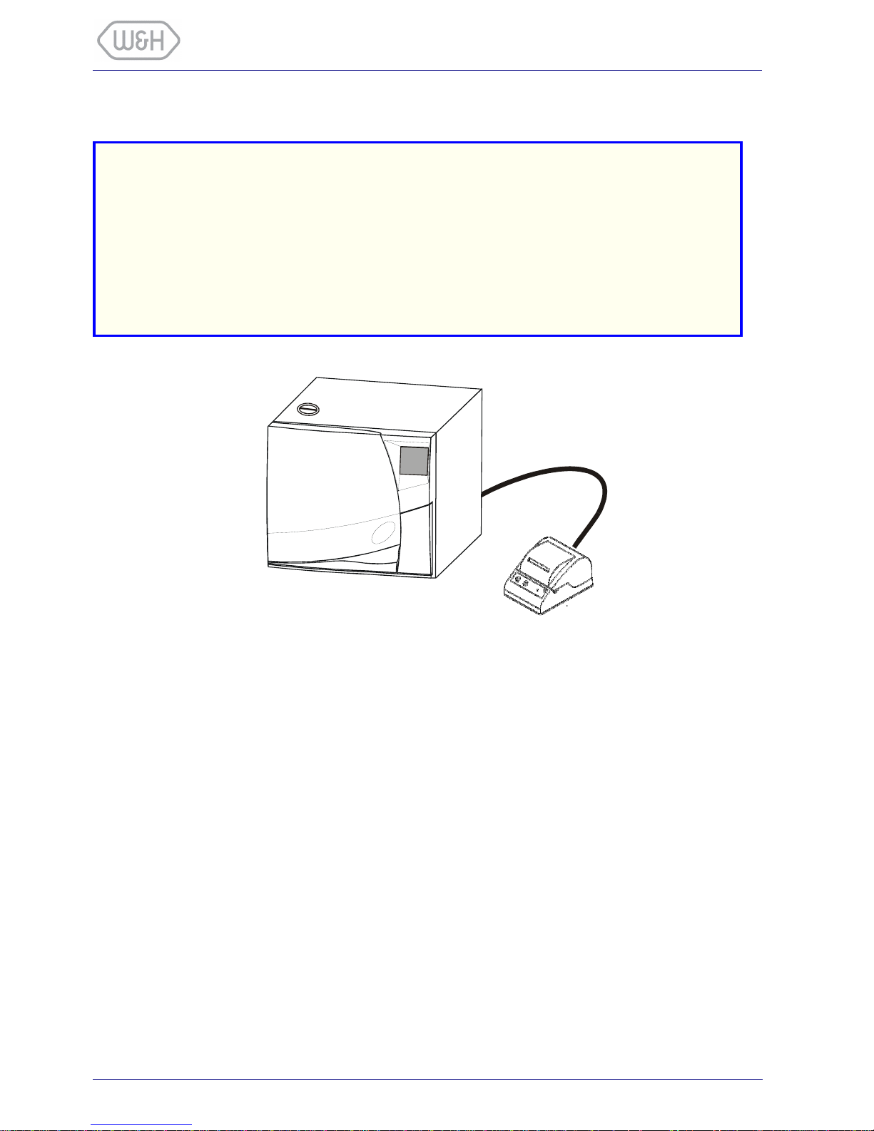
2.3. PRINTER CONNECTION (OPTIONAL)
Connect the printer cable to the 25 pin parallel port socket at the back of the sterilizer.
Cable length should not exceed 2 metres.
Plug in the printer mains cable.
Switch ON the printer.
Switch ON the sterilizer.
Select the printer type (§ 4.5.4.).
All the information needed to document the sterilization cycles is printed:
- The name of the Doctor / surgery (§ 4.5.2.).
- The serial number of the sterilizer.
- The chronological number of the cycle.
- The date and time at the beginning and at the end of the cycle.
- The cycle selected.
- The duration, temperature and pressure of the various phases.
- Comments on cycle efficiency.
Attention !
We recommend to use the following printer:
- Custom DP40H.
It has been tested and is perfectly compatible with the sterilizer and its software.
The use of another printer is undertaken with the full responsability of the user, clearing the
manufacturer, W&H l
STERILIZATION
of responsability for warranty and any other claim.

9
User manual
3. DESCRIPTION
3.1. FRONT VIEW OF THE STERILIZER
Door
Touch screen
Service door
Main switch / circuit breaker *
Switch ON/OFF of the sterilizer.
Use this switch to interrupt a cycle
only in the case of a noted defect.
* Replaces the fuses.
Main water tank
drain connection
Bacteriological filter
Used water tank
drain connection
9 pin serial port
For technical department only.

User manual
10
3.2. REAR VIEW OF THE STERILIZER
25 pin printer port
Mains plug socket
Condenser ventilation
Connection for external
used water drainage
Compliance plate

11
User manual
4. USE
4.1. MAIN MENU
Activate the mains switch, the selection screen appears.
If the sterilizer is not used for a certain period of time, it
will automatically go into stand-by mode.
Stand-by mode time is programmable (§ 4.5.6.).
Cycle selection
(§ 4.6.2.)
Access to sub
menus (§ 4.5.)
Manual
stand-by
When the sterilizer is switched ON, the chamber is automatically heated to 110°C.
Pre-heating starts from room temperature and takes approximately 10 minutes.
It is nevertheless possible to select and start a cycle before the end of pre-heating.

User manual
12
4.2. DESCRIPTION OF THE WATER TANK
The sterilizer is equipped with 2 independent water tanks of equal volume - 3.5 litres (MB17) or 4,5 litres (MB22).
The left tank also called the "main tank" contains the distilled or demineralized water required for each cycle.
It is fitted with 2 level sensors, minimum (0.5 l) and maximum (3.5 l on MB17 or 4.5 l on MB22).
The right tank called the "used water tank" contains the used water collected at the end of each cycles.
It is fitted with a maximum level sensor (3.5 l on MB17 or 4.5 l on MB22).
The 2 tanks are connected to drain connections located behind the service door.
The water consumption per cycle varies depending on the type and mass of the sterilized load.
The following message is displayed on the screen when the minimum water level is reached in the main tank:
While the message is displayed, it is impossible to run another cycle.
The selection button has disappeared !
Main water tank
Main water tank
drain connection
Used water tank
drain connection
Used water
tank
The sterilizer will run for at least 8 cycles before the main tank needs refilling.
F I L L T H E
W AT E R T A N K

13
User manual
4.3. FILLING OF THE MAIN WATER TANK
Remove the main water tank cap located on the top of the
sterilizer
…
…Fill the tank with approx. 3 litres on MB17 (or 4 litres on MB22) of water...
…Once the tank is almost full, an audible tone will be heard.
When you hear the tone proceed carefully. You must stop
filling as soon as the water level reaches the lower edge of the
opening to the water tank.
If the sterilizer is not used for more than 3 days, both water tanks must be
completely drained in order to avoid alga growth or any other deposits.
Attention !
Use only high quality distilled or demineralized water (see Annex 7).
The water from the main tank (3 litres on MB17 or 4 litres on MB22) has been used for a series of
cycles.
This water has been drained off and stored in the used water tank which will be full.
While the main tank is re-filled, the used water tank must be drained in the meantime (see § 4.4.).
 Loading...