


Table of Contents
1. INTRODUCTION................................................................................................................................................... 1
1.1 SCOPE ...................................................................................................................................................... 1
1.2 FOREWORD ............................................................................................................................................. 1
1.3 APPLICABLE EUROPEAN DIRECTIVES/NORMS ................................................................................... 1
1.4 INTENDED USE ........................................................................................................................................ 1
1.5 SYMBOLS DISPLAYED ON THE STERILIZER ........................................................................................ 2
1.6 GENERAL AND SAFETY RECOMMENDATIONS .................................................................................... 2
2. UNPACKING ........................................................................................................................................................ 3
2.1 UNPACKING THE STERILIZER ................................................................................................................ 3
2.2 STANDARD ACCESSORIES .................................................................................................................... 3
3. UNIT DESCRIPTION ............................................................................................................................................ 4
3.1 FRONT VIEW ............................................................................................................................................ 4
3.2 SERVICE DOOR ....................................................................................................................................... 4
3.3 REAR VIEW ............................................................................................................................................... 5
3.4 DESCRIPTION OF THE INTERNAL WATER TANKS ............................................................................... 6
3.5 CHAMBER RACK ...................................................................................................................................... 7
3.6 USABLE SPACE IN THE CHAMBER ................................ ................................................................ ........ 7
4. INSTALLATION .................................................................................................................................................... 8
4.1 SETUP ....................................................................................................................................................... 8
4.1.1 Securing the sterilizer with a safety bracket ................................................................................. 8
4.2 ELECTRICAL POWER SUPPLY ............................................................................................................... 9
4.3 PRINTER (optional) ................................................................................................................................... 9
4.4 LISAWARE - CONNECTING THE STERILIZER TO A COMPUTER (optional) ....................................... 10
4.4.1 LAN connection ......................................................................................................................... 10
4.4.2 Serial connection ....................................................................................................................... 10
4.5 DEMINERALIZER (optional) .................................................................................................................... 11
4.5.1 Connecting an external water supply system (demineralizer) .................................................... 11
4.6 CONTINUOUS DRAINING (optional) ...................................................................................................... 11
4.6.1 Connecting the drain tube .......................................................................................................... 11
5. GETTING STARTED .......................................................................................................................................... 12
5.1 THE USER INTERFACE ......................................................................................................................... 12
5.2 INITIAL WARNINGS AND SLEEP MODE ............................................................................................... 13
5.3 DATE-CLOCK SETTING ......................................................................................................................... 13
5.4 FILLING THE CLEAN WATER TANK ...................................................................................................... 14
5.4.1 Manual filling .............................................................................................................................. 14
5.4.2 Automated water supply (optional) ............................................................................................ 14
5.5 DRAINING THE USED WATER TANK .................................................................................................... 15
5.5.1 Manual draining ......................................................................................................................... 15
5.5.2 Continuous draining ................................................................................................................... 15
5.6 MEMORY CARD ..................................................................................................................................... 15
5.6.1 Inserting / removing the memory card ....................................................................................... 15
6. PROGRAMMING ................................................................ ................................................................................ 16
6.1 SETUP MENU ......................................................................................................................................... 16
6.1.1 Language ................................................................................................................................... 16
6.1.2 Sleep mode ................................................................................................................................ 17
6.1.3 Printer ................................ ................................ ........................................................................ 17
6.1.4 Label printer (available only when a LisaSafe label printer is connected) .................................. 17
6.1.5 Automatic printing (available only when a LisaSafe label printer is connected) ......................... 17
6.1.6 Manual printing (available only when a LisaSafe label printer is connected) ............................. 17
6.1.7 Storage time/weeks (available only when a LisaSafe label printer is connected) ...................... 17
6.1.8 User name ................................................................................................................................. 17
6.1.9 Date-Clock setting ..................................................................................................................... 17
6.1.10 Date format ................................................................................................................................ 18
6.1.11 Clock format ............................................................................................................................... 18
6.1.12 Display contrast ......................................................................................................................... 18
6.1.13 Display backlight ........................................................................................................................ 18
6.1.14 Acoustic tones ........................................................................................................................... 18
6.1.15 Night cycle shortcut ................................................................................................................... 19
6.1.16 Connection to PC/Log ................................................................................................................ 20
6.1.17 RSDATA port selection .............................................................................................................. 20
6.2 TEST CYCLES ........................................................................................................................................ 21
6.3 DELAYED CYCLE START ...................................................................................................................... 22
6.4 CYCLE HISTORY .................................................................................................................................... 23
6.5 MAINTENANCE ....................................................................................................................................... 24
6.6 SERVICE ................................................................................................................................................. 24
6.7 UTILITY ................................................................................................................................................... 24
a

6.7.1 System info ................................................................................................................................ 25
6.7.2 Formatting the memory card ...................................................................................................... 25
6.8 USER AUTHENTICATION ...................................................................................................................... 25
6.9 FUNCTIONS AVAILABLE FOR THE ADMINISTRATOR ........................................................................ 26
6.9.1 Access the administrator functions ............................................................................................ 26
6.9.2 Modifying a user name .............................................................................................................. 27
6.9.3 Changing the administrator’s password ..................................................................................... 28
6.9.4 Resetting a user’s password to the default value (0000) ........................................................... 29
6.9.5 Deleting a user........................................................................................................................... 30
6.9.6 Adding a new user ..................................................................................................................... 31
6.9.7 Setting the user identification options for all users ..................................................................... 32
6.10 FUNCTIONS AVAILABLE TO THE OPERATOR(S): PASSWORD MODIFICATION .............................. 33
6.11 STARTING AND ENDING A STERILIZATION CYCLE WITH IDENTIFICATION OF THE USER .......... 35
6.11.1 Starting a sterilization cycle ....................................................................................................... 35
6.11.2 End of a sterilization cycle ......................................................................................................... 36
7. RUNNING A STERILIZATION CYCLE .............................................................................................................. 37
7.1 THE AVAILABLE STERILIZATION CYCLES .......................................................................................... 37
7.1.1 Starting a sterilization cycle ....................................................................................................... 39
7.1.2 ECO-Dry feature ........................................................................................................................ 39
7.1.3 Cycle in-progress ....................................................................................................................... 40
7.1.4 End of cycle ............................................................................................................................... 40
7.2 MANUAL STOP ....................................................................................................................................... 41
7.3 REAL-TIME CYCLE DATA INFORMATION ............................................................................................ 42
7.4 CYCLE DATA SUMMARY ....................................................................................................................... 43
8. DISPLAY MESSAGES ....................................................................................................................................... 44
9. ALARMS ........................................................................................................................................................... 46
10. ALARM CODE TABLE ....................................................................................................................................... 47
11. MAINTENANCE ................................................................................................................................................. 49
11.1 MAINTENANCE PROGRAM ................................................................................................................... 49
11.2 CLEANING THE DOOR SEAL ................................................................................................................ 50
11.3 CLEANING THE CHAMBER AND CHAMBER COMPONENTS ............................................................. 50
11.4 CLEANING THE CHAMBER FILTER ...................................................................................................... 50
11.5 CLEANING THE EXTERNAL STERILIZER SURFACES ........................................................................ 51
11.6 REPLACING THE BACTERIOLOGICAL FILTER .................................................................................... 51
11.7 REPLACING THE DUST FILTER ............................................................................................................ 51
11.8 CLEANING THE WATER TANKS ........................................................................................................... 52
11.9 REPLACING THE DOOR SEAL .............................................................................................................. 53
11.10 SERVICE CONDUCTED BY AN AUTHORIZED SERVICE TECHNICIAN .............................................. 54
12. USE OF THE MEMORY CARD .......................................................................................................................... 55
12.1 TECHNICAL CHARACTERISTICS OF THE MEMORY CARD ............................................................... 55
12.2 READING OF MEMORY CARD DATA WITH A PC/MAC ....................................................................... 55
12.3 MINIMUM HARDWARE REQUIREMENTS FOR A PC/MAC .................................................................. 55
12.4 CONNECTING THE EXTERNAL USB CARD READER TO YOUR PC/MAC ......................................... 56
12.5 SAVED FILE ............................................................................................................................................ 56
12.6 CONTROL CODE .................................................................................................................................... 56
12.7 FILE NAMES ........................................................................................................................................... 56
12.8 DIRECTORY NAME ................................................................................................................................ 56
12.9 MEMORY CARD MANAGEMENT ........................................................................................................... 57
12.10 SAVING A FILE ....................................................................................................................................... 58
13. TROUBLESHOOTING ....................................................................................................................................... 59
14. RECYCLING / DISPOSAL INSTRUCTIONS ...................................................................................................... 60
Appendix 1 TECHNICAL CHARACTERISTICS ................................................................................................... 61
Appendix 2 STERILIZATION LOAD PREPARATION .......................................................................................... 62
Appendix 3 MAINTENANCE OF DENTAL HANDPIECES ................................................................................... 63
Appendix 4 BOWIE AND DICK TEST .................................................................................................................. 64
Appendix 5 HELIX TEST ...................................................................................................................................... 65
Appendix 6 VACUUM TEST ................................................................................................................................. 66
Appendix 7 WATER QUALITY ............................................................................................................................. 67
Appendix 8 EXAMPLE OF A CYCLE DATA REPORT ........................................................................................ 68
Appendix 9 ACCESSORIES ................................................................................................................................. 69
Appendix 10 HELIX TEST DOCUMENTATION FORM .......................................................................................... 71
b
1. INTRODUCTION
NOTE:
All drawings, images and texts contained in this manual are the property of the manufacturer.
All rights reserved. Even partial duplication of drawings, images or text is prohibited.
The information contained in this document is subject to change without notice.
1.1 SCOPE
The purpose of this user manual is to provide you with information about Lisa 517/522 sterilizers to
ensure:
proper installation and set-up.
optimal use.
safe and reliable operation.
compliance with regular maintenance and servicing requirements.
1.2 FOREWORD
There are two types of users who may operate the sterilizer and who shall read this manual carefully:
Administrator
The head of the clinic / practice, who is legally responsible for the efficiency of the hygiene protocol in
place as well as the sterilization process. He/she is also responsible for the OPERATORS’ training and
the correct operation and maintenance of the equipment.
Operator
The person(s) who use(s) the sterilizer according to the ADMINISTRATOR’S instructions.
1.3 APPLICABLE EUROPEAN DIRECTIVES/NORMS
Lisa 517/522 sterilizers conform to the following European Directives:
Medical Device Directive 93/42/CEE for devices class IIb, in accordance with rule 15 - Appendix IX
of the above directive.
Directive 97/23/CEE (Pressure Equipment Directive – PED) for every sterilization chamber
designed and manufactured in conformity to Annex I and to the procedure described in form
D1 annex III.
Directive 2002/96/CEE (RAEE) for disposal of parts coming from electrical or electronic
parts.
The sterilizer has been developed, produced and tested in accordance with the European
Norm relative to small water steam sterilizers EN13060, and with the applicable safety
norms (see Appendix 1).
In the enclosed documents, you will find the Declaration of Conformity and a Warranty Card specific to your sterilizer.
1.4 INTENDED USE
Lisa 517/522 sterilizers are fully automated bench top steam sterilizers that generate steam using electrical
heaters.
Lisa 517/522 sterilizers are used for medical purposes, e.g. in general medical practices, dental offices, facilities for personal hygiene and beauty care and veterinary practices. They are also used for materials and
equipment that is likely to be exposed to blood or body fluids, e.g. instruments used by beauty therapists,
tattooists, body piercers and hairdressers.
The types of loads that can be sterilized with Lisa sterilizers are described in Table 1 of the reference technical norm EN 13060. These loads include solid, porous, hollow loads type A and hollow loads type B, unwrapped, single wrapped and double wrapped.
Lisa sterilizers cannot be used to sterilize liquids or pharmaceutical products.
1
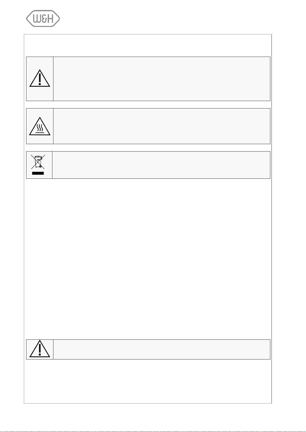
ATTENTION
Where this symbol is displayed on the sterilizer, the user must refer to this document.
When shown in the user manual this symbol means ATTENTION IMPORTANT NOTES.
To disregard the instructions given in this manual, incorrect use, poor maintenance or
servicing by unauthorized personnel, clears the manufacturer of any responsibility for
warranty and any other claims.
HOT SURFACES
This symbol is displayed at the front of the sterilizer beneath the chamber door. It reminds the user to take special care to avoid burns when dealing with the sterilization
load, the sterilization chamber, the chamber door and the area around the chamber
door.
The material the sterilizer is composed of must be disposed according to the directive
2002/96/CEE.
Not observing the instructions as specified in this manual can lead to unsafe operation for the user.
1.5 SYMBOLS DISPLAYED ON THE STERILIZER
Consult this table whenever one you see one of these symbols in this manual or on the sterilizer.
1.6 GENERAL AND SAFETY RECOMMENDATIONS
o The user is responsible for the proper installation, the correct use and maintenance of the steri-
lizer in accordance with the instructions listed in this manual. For further information call your
local service provider.
o The sterilizer has not been designed for the sterilization of liquids.
o The sterilizer must not be used in the presence of gas or explosive vapours.
o The chamber is automatically heating to 120°C as soon as the sterilizer is switched on.
o The trays and the sterilization load will be hot at the end of each cycle. Use tray or cassette
holders to empty the sterilization chamber.
o Do not exceed the maximum load weight limits as specified in this manual (see § 7.1)
o Do not remove the name plate or any label from the sterilizer.
o To avoid electrical short circuits, do not pour water or any other liquid over the sterilizer.
o Switch off the sterilizer and unplug the mains cable before inspecting, carrying out maintenance
or servicing the sterilizer.
o Repairs, maintenance or service must be carried out by authorized W&H service technicians
only with the use of original spare parts.
o In case of transport:
- Drain both water tanks completely (§ 5.5).
- Allow the sterilization chamber to cool down.
- Use original or appropriate packaging.
2
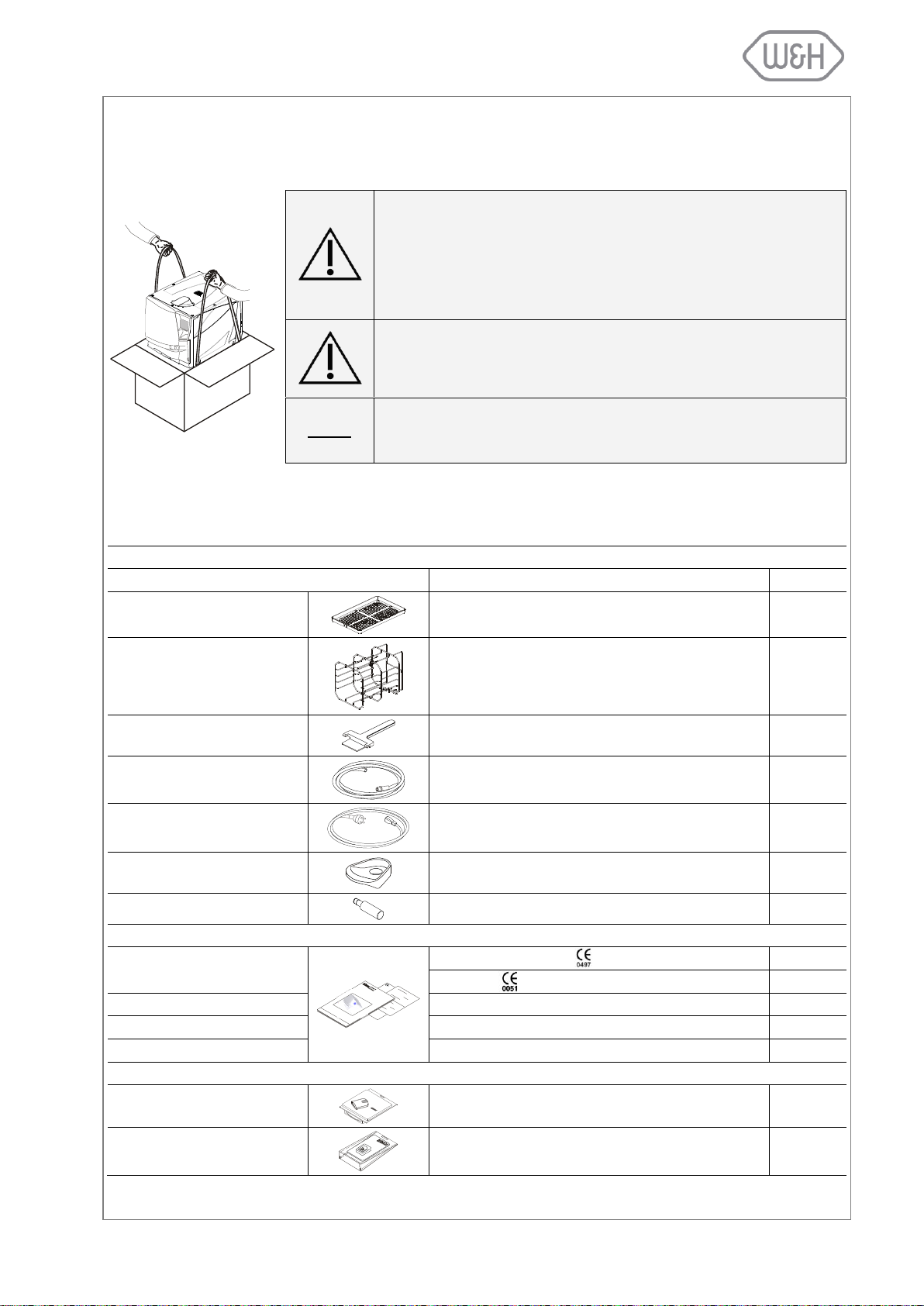
2. UNPACKING
If the sterilizer had been kept in a place with temperature and
humidity different from the installation location, wait for an appropriate time before installing and switching ON the sterilizer. Sterilizers arriving from cold locations could contain moisture, affecting
the electrical parts and it could lead to unsafe operation for the
user if switched ON immediately.
The sterilizer must be removed from the box and transported by
two people.
Total weight:
Lisa 517 40 kg
Lisa 522 50 kg
NOTE:
Check the external condition of the box and the sterilizer. In case of any
damages, immediately contact your dealer or the shipping agent that has
carried out the transport.
ACCESSORIES PLACED INSIDE THE STERILIZATION CHAMBER
Accessory
Description
Quantity
Tray
Perforated anodized aluminum tray
5
Reversible rack
Stainless steel rack to accommodate 5 trays or 3
cassettes.
Optional racks available (see Appendix 8). For more
information contact your dealer.
1
Tray holder
Tray holder for removing trays from the sterilization
chamber.
1
Drain tube
Transparent drain tube with quick connector
1
Mains cable
Length = 2 meters
1
Funnel
Funnel to fill the clean water tank.
1
Wall spacer
Spacer to keep distance between wall and steril.
2
DOCUMENTS PLACED INSIDE THE PACKAGE
Declaration of conformity CE
Sterilization chamber:
1
Sterilizer:
1
User manual
Current user manual
1
Warranty card
Warranty card
1
Works Test Report
Norm EN 13060: small steam sterilizers.
1
ACCESSORIES PLACED INSIDE THE PACKAGE
Memory card USB reader
External memory card reader
1
Memory card
Reads and saves cycle data
1
2.1 UNPACKING THE STERILIZER
2.2 STANDARD ACCESSORIES
Following accessories are supplied together with the sterilizer:
3
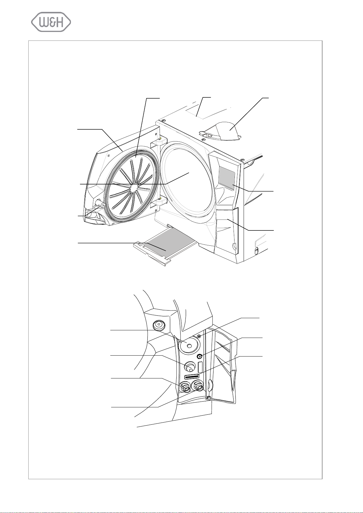
Sliding cover for
manual filling of
the clean water
tank
Service door
Chamber
door
Door seal
Sterilization
chamber
Dust filter
Touch- screen
Door pin
Water tank cover
Bacteriological filter
Main switch
Quick connector for
manual draining of
clean water tank
Quick connector for
manual draining of
used water tank
Connection to unlock
the chamber door (service technicians only)
Connection for the
Air Detector Test
Device (optional)
Memory card slot
3. UNIT DESCRIPTION
3.1 FRONT VIEW
3.2 SERVICE DOOR
4
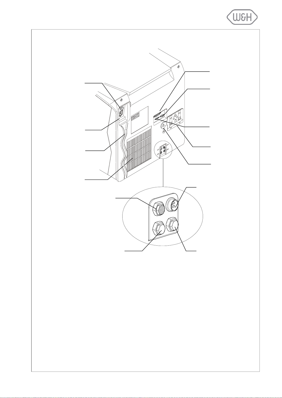
3.3 REAR VIEW
Circuit breaker
(manual reset)
Mains plug socket
Condenser vent
Mains cable guide
Parallel port
(printer)
Safety valve cover
Male serial port
Air filter
Plug for an external
water supply system
Test connection
D1
D2
D3
D4
Fitting for continuous
draining of used water
Fitting for an external
water supply system
Female serial port
5
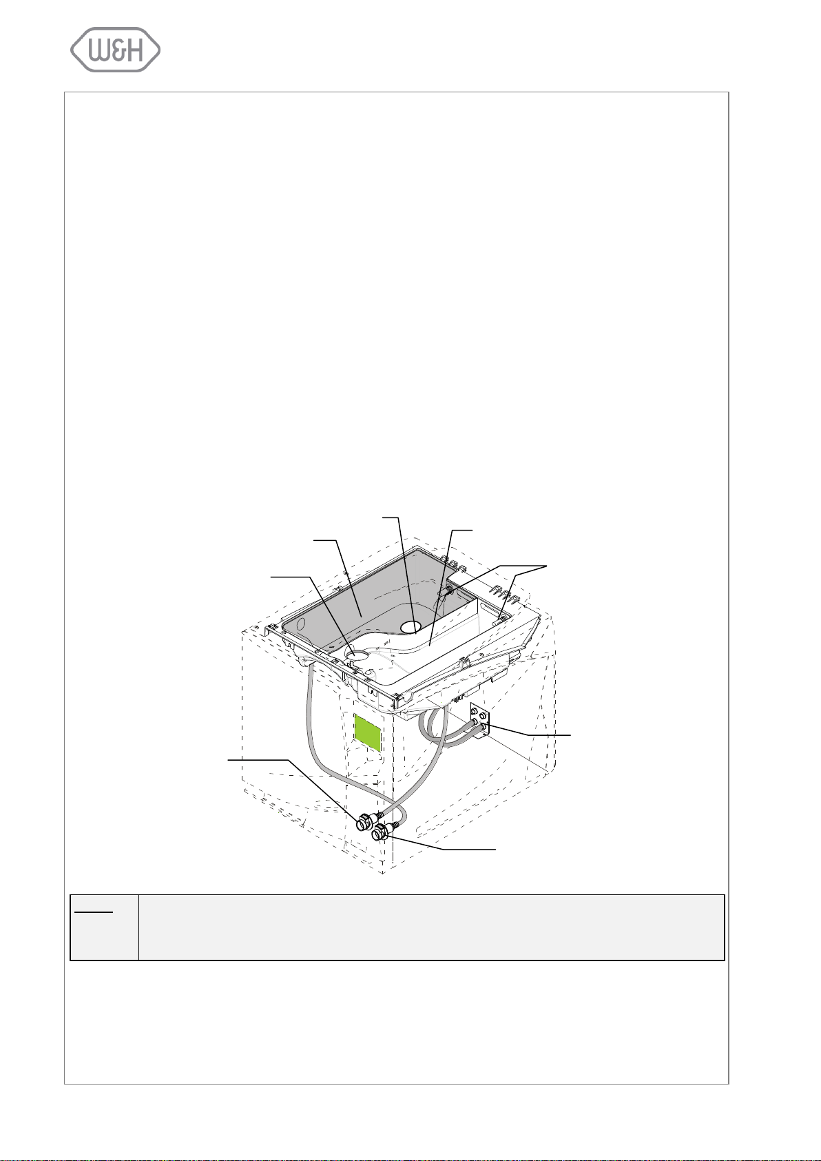
NOTE:
The water consumption per sterilization cycle varies depending on the type and weight of the
sterilization load. The capacity of the clean water tank is sufficient to run 8 - 12 sterilization
cycles.
Used water tank
Water level sensors
Quick connector for
manual draining of
clean water tank
Quick connector for manual draining of used
water tank
Water inlet for manual filling of
clean water tank
Fittings for automatic filling/draining of tanks
Clean water tank
Vent
3.4 DESCRIPTION OF THE INTERNAL WATER TANKS
The sterilizer is equipped with two independent water tanks, one for clean water and one for used water
(capacity of 3.5 litres each).
The tank on the right side is called "clean water tank" and has to be filled with distilled or demineralized
water required for the sterilization process. It is fitted with a minimum (0.6l) and a maximum (3.5l) water
level sensor. The tank can be filled manually through the tank hole on the top of the sterilizer or automatically with an external water supply system (Dem 32 or Osmo) connected to point D2 at the back of the sterilizer (see § 4.5.1).
Use the quick connector behind the service door (left/blue) to drain the clean water tank for cleaning purposes (see chapter on maintenance).
The tank on the left side is called "used water tank" and contains the used water collected at the end of
each sterilization cycle. It is fitted with a maximum water level sensor (3.5l).
Use the quick connector behind the service door (right/grey) to drain the used water tank (see chapter on
maintenance).
The used water tank can also be drained automatically by connecting a drain tube to the D4 fitting located
at the back of the sterilizer (see § 4.6).
6
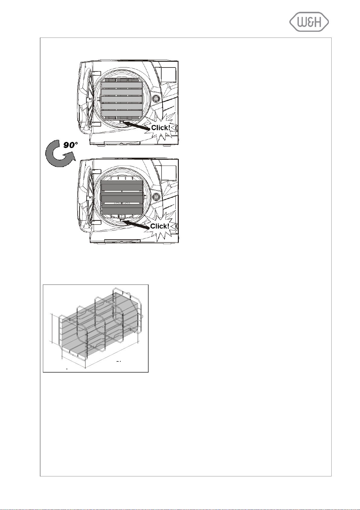
3.5 CHAMBER RACK
Insert the rack into the sterilization chamber, align it
at the center/bottom of the chamber and push it
gently into position until it clicks.
The chamber rack is reversible and can be used
for:
5 trays horizontally or 3 cassettes vertically;
or, if inserted in a 90° degree rotated position,
3 trays or 3 cassettes horizontally.
The chamber usable space is the maximum volume of the
chamber for accommodating a sterilization load. This volume is
equivalent to a pipe with the following dimensions:
Lisa 517
195 x 195 x 297mm (WxHxD); equal to the volume of 11.5 litres
Lisa 522
195 x 195 x 390mm (WxHxD); equal to the volume of 15 litres
The capacity/volume is identical for all sterilization cycles and
types of load.
H
W
D
3.6 USABLE SPACE IN THE CHAMBER
7
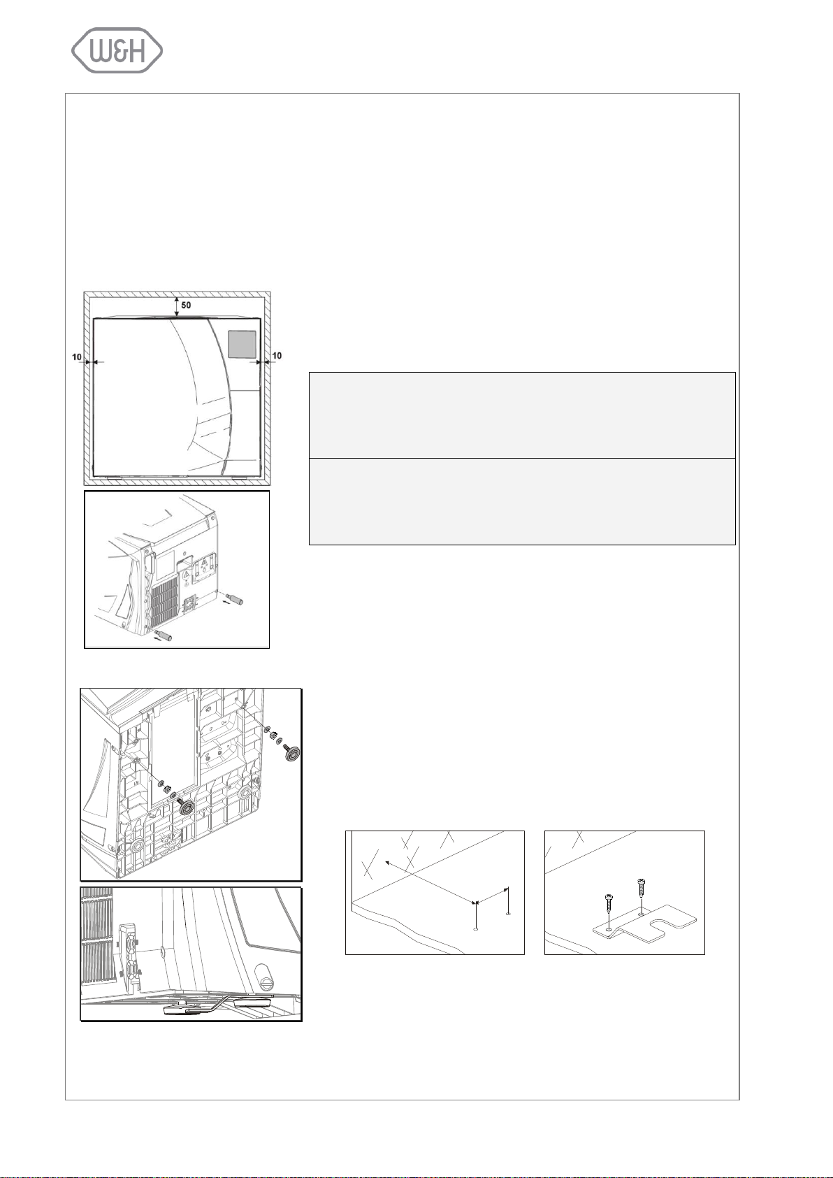
Install the sterilizer as outlined below:
Place the sterilizer on a flat and level surface.
Do not place the sterilizer so that it is difficult to open the service
door and operate on the controls in it (main switch, microbiological
filter, drains)
The maximum weight of the sterilizer with a full clean water tank
and the chamber fully loaded is:
52 kg (Lisa 517)
63 kg (Lisa 522)
Leave a gap of 50mm in the back and 10mm on each side of the
sterilizer to ensure adequate ventilation.
Mount the supplied wall spacers at the back of the sterilizer
(see image to the right).
Do not place the sterilizer near a sink or in a location where it is
likely to be splashed with water - danger of electric short circuit!
Install the sterilizer in a well-ventilated room.
Keep the sterilizer away from all sources of heat.
If the bench on which the sterilizer is installed is small, there is a
risk of the sterilizer tilting when the chamber door is opened and
leaned upon.
Use the safety bracket (optional; see Appendix 9) to avoid tilting.
- Move the two front feet in the rear position.
- Drill two holes on the installation surface and fix the bracket
with the supplied screws.
40
113
Refer to safety bracket installation procedures for further details.
Position the sterilizer on the bench with one of the rear feet inserted in the safety bracket.
Wall
Minimum distance
(millimeters)
2 holes Ø3x20
Screws Ø4,8x22
4. INSTALLATION
4.1 SETUP
The sterilizer has been calibrated and intensively tested in the factory prior to shipping. It does not require
any calibration during installation.
Observe the following environmental conditions:
Working temperature range: from +5°C to +40°C / relative humidity: 0 - 90%
Storage temperature range: from -20°C to +60°C / relative humidity: 0 - 90% (empty tanks)
4.1.1 Securing the sterilizer with a safety bracket
8
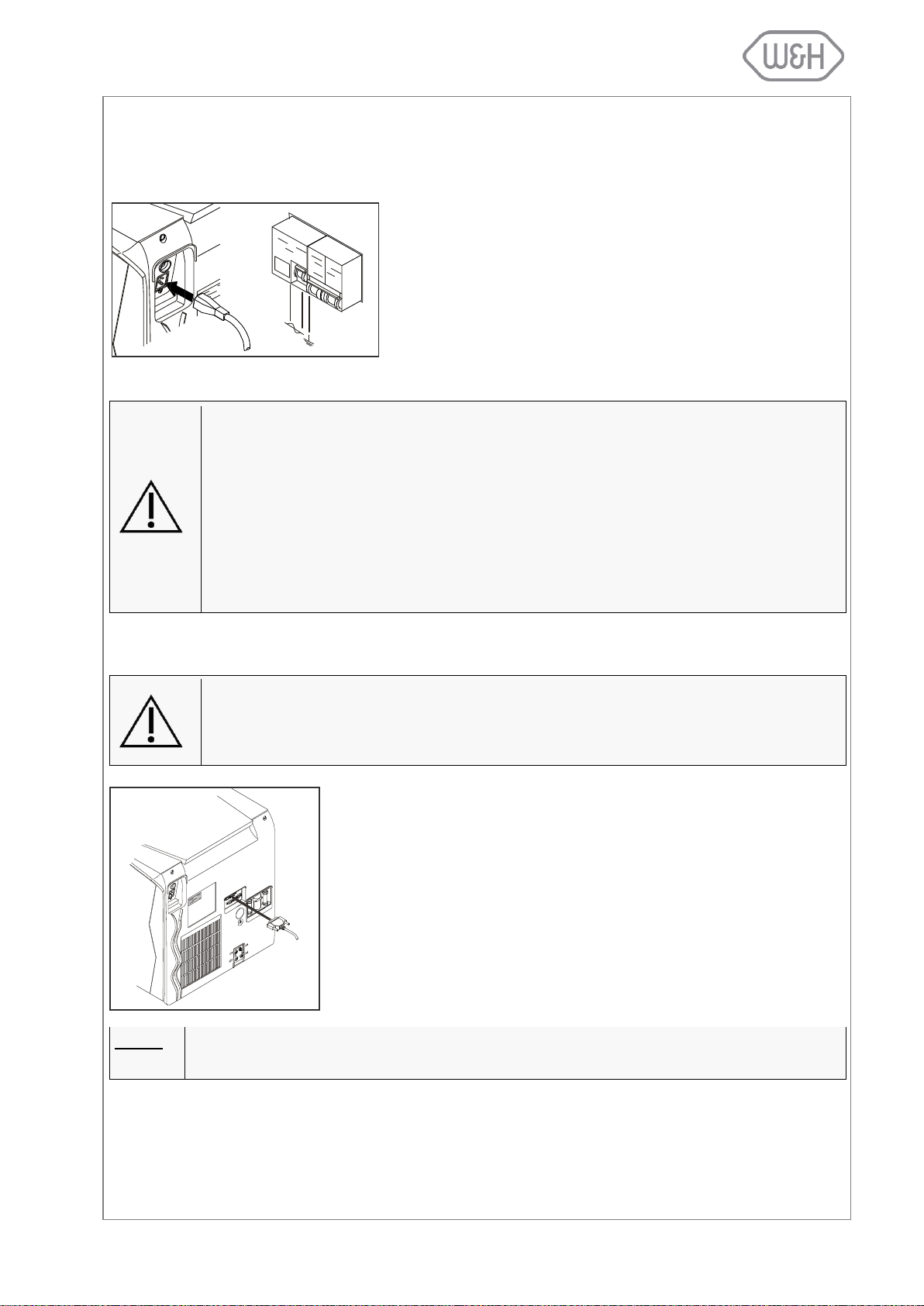
4.2 ELECTRICAL POWER SUPPLY
- Single - phase 200 - 240 VAC ±10%, 50/60 Hz, 10 A, on a
dedicated circuit.
- Installation category / mains overload category = II
- 10 A differential circuit breaker with a sensitivity of 30 mA.
The circuit breaker must be a certified type according to applicable norms.
- Maximum power consumption of the sterilizer is 2,000 2,400W (10 A)
- A grounded connection is essential.
Check that the voltage specified on the name plate located on the backside of the
sterilizer corresponds to the supplied mains voltage.
The overall electrical safety of the sterilizer is guaranteed only if the mains voltage
supply is properly grounded according to all applicable norms.
If unclear, have the electrical installation checked by a qualified electrician.
Do not plug other equipment into the same socket/circuit.
Do not bend or twist the mains cable.
Only use the original mains cable as supplied with the sterilizer.
Do not use cable extensions.
We recommend the use of LisaPrint (conforms to the IEC 61010-1 norm) as it has
been tested for compatibility with the sterilizer and its software.
The use of printers other than the ones listed in the relevant printer setup menu (see
6.1.3) clears the manufacturer of any responsibility for warranty or any other claims.
- Connect the printer cable to the 25-pin parallel port socket at the back
of the sterilizer. Cable length should not exceed 2 meters.
- Connect the printer mains cable.
- Switch ON the printer.
- Select the printer type (§ 6.1.3). LisaPrint is the default setting
(Print-p).
All necessary data to document sterilization cycles is automatically printed
(for details see Appendix 8).
NOTE:
Lisa 517/522 sterilizers offer the option to digitally save cycle data on removable memory cards.
The electrical power supply of the sterilizer must comply with all applicable standards in the country of use.
The following characteristics are required:
4.3 PRINTER (optional)
9
W&H does not accept any responsibility should the MOXA interfere with the normal
functioning of your network.
W&H recommend using the MOXA NPort 5110 which has been tested and is compatible with the Lisa sterilizer and its software.
The use of other ethernet to serial adaptors removes all responsibility from the manufacturer in regards to the correct functioning of the system, the warranty and any
other claims.
4.4 LISAWARE - CONNECTING THE STERILIZER TO A COMPUTER (optional)
Connect up to four Lisa 517/522 sterilizers to a computer or computer network with LisaWare, a computer
software that allows automatic saving of cycle data on a computer and the remote monitoring of the cycle
progress on the computer screen.
Sterilizers can be connected to a computer in two ways, either via a LAN connection using a MOXA ethernet to serial adaptor, or via a serial connection.
4.4.1 LAN connection
- Your sterilizer features two serial ports in the back: male and female; either port can be used for
data transfer. Switch on the sterilizer, access the setup menu, enter the “RSDATA port selection”
option and select one of the two available serial ports for data transfer (see 6.1.17).
- Scroll to the “Connection to PC/Log” option in the setup menu and select and confirm “yes” (see
6.1.16).
- Please refer to the MOXA configuration sheet for instructions on how to configure your MOXA
NPort 5110 to your network.
- Once you have configured your MOXA, use one of the supplied serial cables (F-F and F-M) to
connect the MOXA to the serial port you selected for data transfer.
- Connect the MOXA to the LAN using an ethernet cable (or if connecting directly to the computer
use a cross-wire cable).
- Use the supplied cable to connect the MOXA to the mains power supply.
For further information, please refer to the “Connection Lisa to LAN or PC” quick-start guide.
4.4.2 Serial connection
- Your sterilizer features two serial ports in the back: male and female; either port can be used for
data transfer. Switch on the sterilizer, access the setup menu, enter the “RSDATA port selection”
option and select one of the two available serial ports for data transfer (see 6.1.17).
- Scroll to the “Connection to PC/Log” option in the setup menu and select and confirm “yes” (see
6.1.16).
- Use one of the supplied serial cables (F-F and F-M) to connect the sterilizer (from the selected
serial port) directly to the serial port on your computer.
For further information, please refer to the “Connection Lisa to LAN or PC” quick-start guide.
10
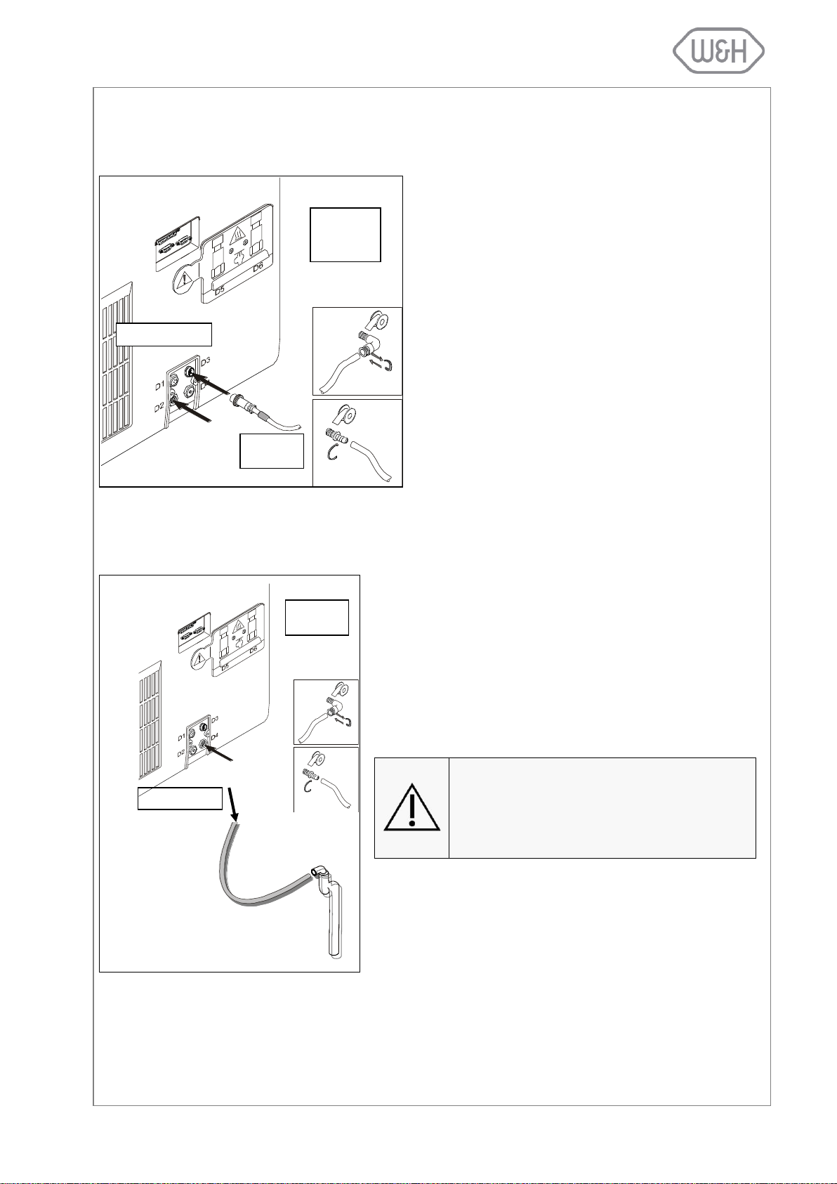
4.5 DEMINERALIZER (optional)
Once installed, the clean water tank no longer needs
to be filled manually but will be filled automatically
with demineralized water. The Dem32/Osmo features
resin cartridges to remove minerals from city water to
assure a constant supply of good quality water for the
sterilization process.
4.5.1 Connecting an external water
supply system (demineralizer)
To install a Dem32/Osmo water supply system, an
interface cable and the fittings D2 and D4 located at
the back of the sterilizer are used.
For more information, refer to the Dem32/Osmo user
manuals.
The sterilizer can be connected to a drain (or simply to a sink)
for continuous draining of the used water tank.
- Unscrew the plug from the D4 fitting at the back of the steri-
lizer.
- Install the 1/8” barb fitting and the drain tube from the kit
and route the tube to a drain or sink (kit ordering number:
G0053060). If unclear, have the installation checked by a
qualified plumber.
The drain tube must not be longer than 5
meters.
The draining point must be at least 20cm
below the surface on which the sterilizer is
placed.
For further information, refer to the Dem32/Osmo user manuals.
D4 = draining
DRAIN
WATER
SUPPLY
Interface
cable
D2 = filling
W&H Sterilization offers external water supply systems for automated supply of demineralized water to the
sterilizer(s) (Dem32 or Osmo).
4.6 CONTINUOUS DRAINING (optional)
4.6.1 Connecting the drain tube
11

To power the sterilizer press the main switch located behind the service
door (see image to the left).
When the sterilizer is switched ON, the chamber automatically heats to 120°C.
This process (pre-heating) takes approximately 10 minutes.
If a sterilization cycle is initiated during the pre-heating
phase, it will start automatically once the pre-heating temperature is achieved.
Once the sterilizer is switched on, the following screen appears:
Menu option
Sleep mode
Available cycles
Current date
Current time
Cycle selection
Cycle counter
Selection
confirmation
Start cycle
5. GETTING STARTED
5.1 THE USER INTERFACE
To run a sterilization cycle, place the load in the sterilization chamber and close the chamber door. Select
a cycle by pressing the “Cycle selection” icon and confirm the selection by pressing the “Selection confir-
mation” icon.
A screen will inform you about the maximum load weight limits for the cycle you selected. Initiate the cycle
by pressing the “Start cycle” icon.
12
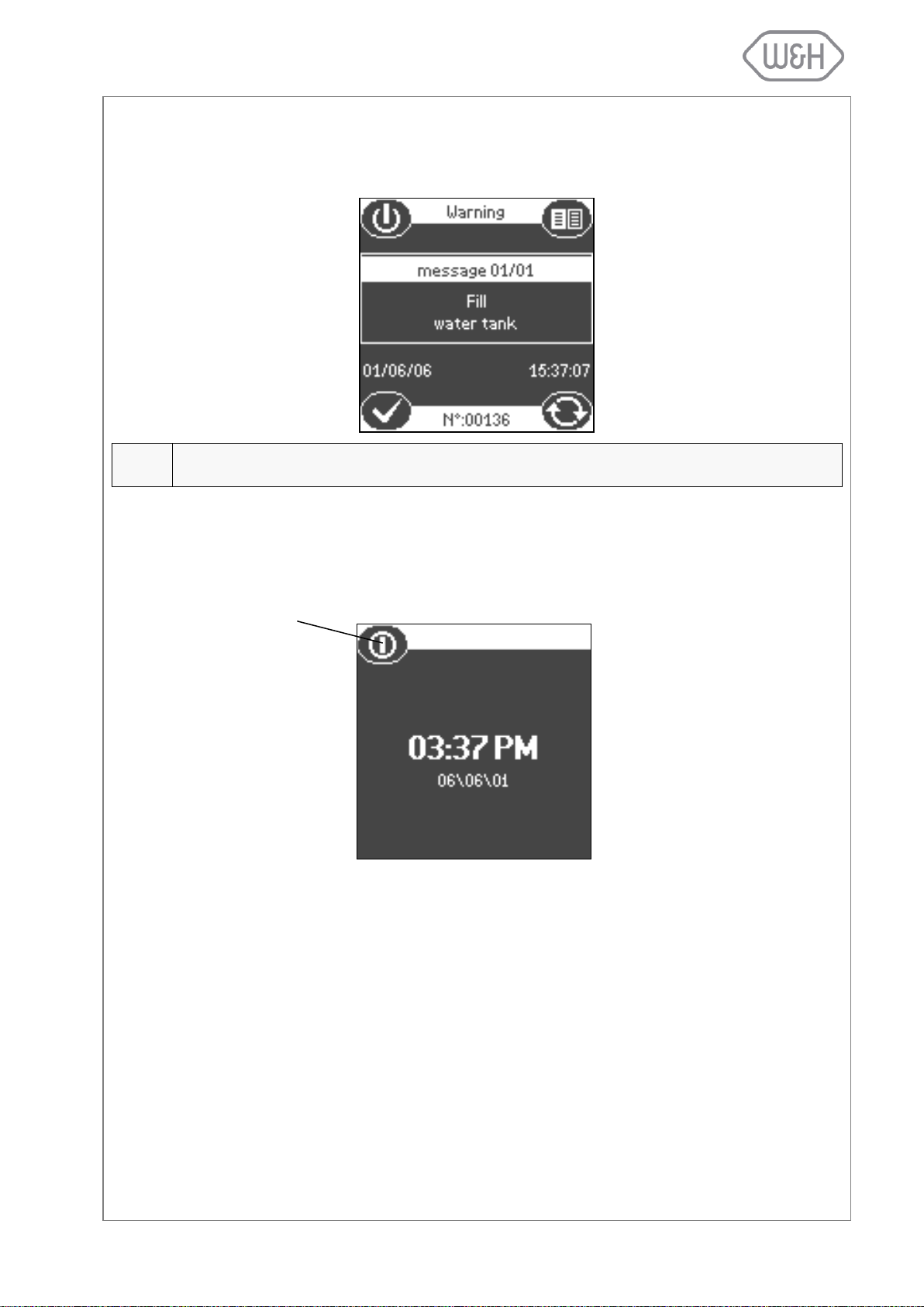
5.2 INITIAL WARNINGS AND SLEEP MODE
NOTE:
If this message is displayed it is not possible to initiate a sterilization cycle. The message disappears automatically once the clean water tank is filled.
Sleep mode
This message will appear if the sterilizer is switched on and the clean water tank is empty. Fill the clean
water tank with distilled or demineralized water (see § 5.4).
If the sterilizer is not used for a certain programmable time period, it will automatically switch to “Sleep
mode” to conserve energy (programmable time-out; default 1 hour; see § 6.1.2). Press the “Sleep mode”
icon to get back to the main menu.
5.3 DATE-CLOCK SETTING
To properly save or print cycle data on a memory card or on a printout, the internal sterilizer time and date
has to be set since these parameters are included in the sterilization cycle data report. Please refer to §
6.1.9 for details on how to properly set the sterilizer date and time.
13
Use only high quality distilled or demineralized water (see Appendix 7).
Slide the tank cover to the right to access the clean
water tank inlet.
Remove the cap (1) from the tank inlet.
Insert the funnel and fill the clean water tank with
app. 3.5 litres of distilled or demineralized water.
Once the clean water tank is almost full, an audible
tone will sound; stop filling.
Place the cap (1) to close the tank.
Slide the tank cover back into its original position.
Drain the used water tank (see § 5.5).
Every time you fill the clean water tank, drain the used water tank (see § 5.5).
If an automated water supply system is connected to the sterilizer (see §
4.5), the clean water tank automatically fills
once the water level drops below the minimum level.
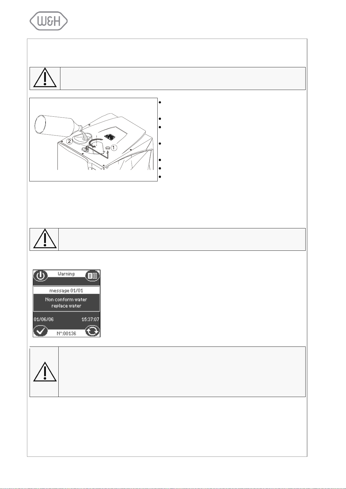
An internal water conductivity sensor constantly monitors the water quality in
regards to mineral content. Should the mineral content go beyond a maximum threshold (>15µS/cm conductivity as defined by the European Norm
EN 13060), a warning message is displayed on the screen (see screenshot
to the left).
Water of low quality with high mineral contents can impair the sterilization process
and seriously damage the internal components of the sterilizer. Damages caused by
water of poor quality will not be covered by the manufacturer’s warranty. Once the non
conform water message is displayed, check the water source (refer to the water supply
system user manual; replace resin cartridges etc.). In case distilled or demineralized
water is purchased, switch to a brand of better quality.
5.4 FILLING THE CLEAN WATER TANK
5.4.1 Manual filling
The water level in the clean water tank decreases during every sterilization cycle, while the water level in
the used water tank is rising. The sterilizer is equipped with an internal water conductivity sensor that constantly monitors the water quality in regards to mineral content. Should the mineral content go beyond a
maximum threshold (conductivity >15µS/cm), a warning message is displayed on the screen.
5.4.2 Automated water supply (optional)
14
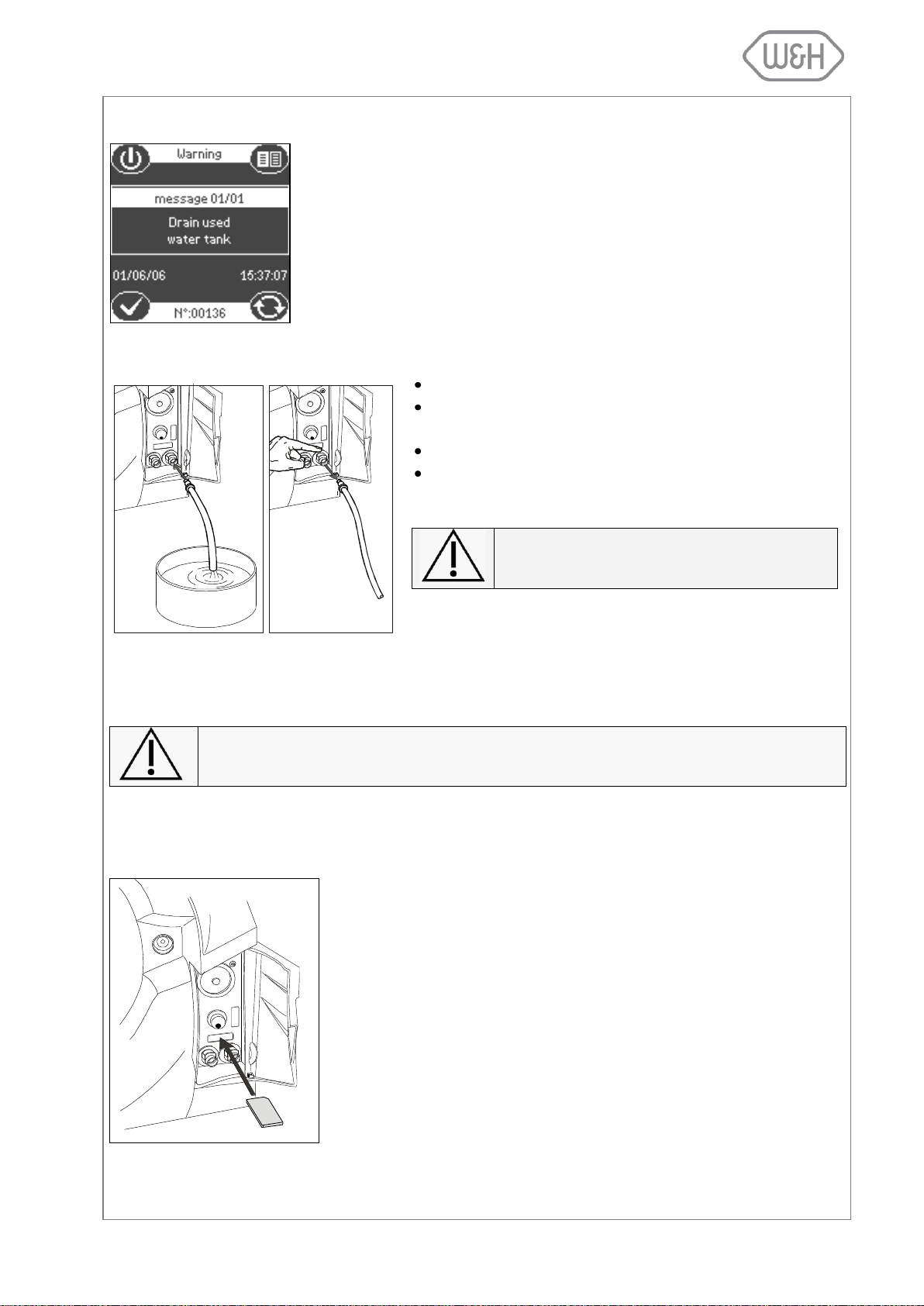
5.5 DRAINING THE USED WATER TANK
When the waste water in the used water tank reaches the maximum level, the
following message is displayed:
The message will disappear once the used water tank got drained. Keep
draining the tank until it is completely empty.
Open the service door at the front of the sterilizer.
Insert the drain tube into the quick connector for the
used water (grey connector / right).
Drain the used water tank until it is completely empty.
Press the push-button on top of the quick connector to
dislodge the drain tube.
Never reuse water from the used water tank!
If the sterilizer is not used for more than 3 days, both water tanks should be completely
drained in order to avoid algae growth or any other deposits.
Lisa 517/522 sterilizers are equipped with a digital cycle data recording
system. Cycle data are written and saved on removable/rewritable memory cards.
- Insert the memory card into the dedicated slot behind the service door
until it clicks into its final position. Ensure that the flat corner of the
card points to the top/right (see image to the right).
- Periodically remove the memory card to download cycle data to a
computer.
- To remove the memory card, slighty push it in and pull it out gently.
For further instructions on the use of the memory card, see §12.
5.5.1 Manual draining
5.5.2 Continuous draining
If the permanent drain tube for automated draining of the used water is mounted, the used water tank gets
drained automatically. For more information see § 4.6.
5.6 MEMORY CARD
5.6.1 Inserting / removing the memory card
15
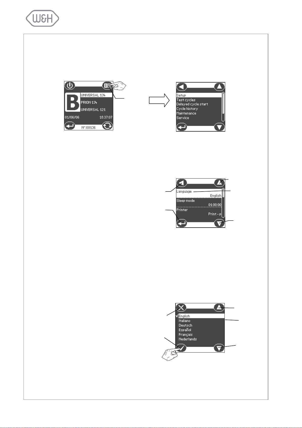
Press the menu icon to view the list of available options.
The available menu options are shown
below:
6.1 SETUP MENU
The Setup menu permits to set the following options:
§ 6.1.1 – Language
§ 6.1.2 – Sleep mode
§ 6.1.3 – Printer
§ 6.1.4 – Label printer *
§ 6.1.5 – Automatic printing *
§ 6.1.6 – Manual printing *
§ 6.1.7 – Storage time *
§ 6.1.8 – User name
§ 6.1.9 – Date-Clock setting
§ 6.1.10 – Date format
§ 6.1.11 – Clock format
§ 6.1.12 – Display contrast
§ 6.1.13 – Display backlight
§ 6.1.14 – Acoustic tones
§ 6.1.15 – Night cycle shortcut
§ 6.1.16 – Connection to PC/Log
§ 6.1.17 – RSDATA port selection
* The sub-menus related to label printing are only
available when the label printer LisaSafe is connected.
6.1.1 Language
Use this menu to select the user interface language.
Menu
Exit and return to
higher menu level
Scroll up
Scroll-down
Current
selection
Confirm and re-
turn to previous
menu
Exit and
return to higher
menu level
Scroll up
Current
selection
Scroll down
Confirm and return to
previous menu
6. PROGRAMMING
Lisa 517/522 sterilizers allow the user to program a number of different features. The following section
shows step by step how each of these features can be programmed.
16
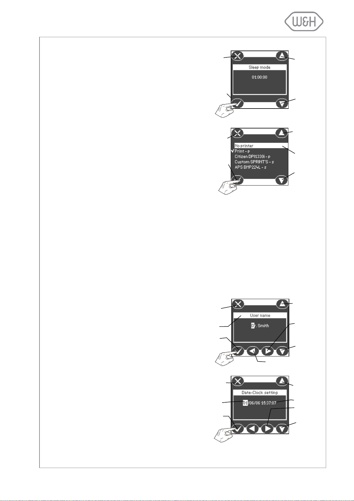
6.1.2 Sleep mode
In “Sleep mode” the sterilizer reduces the
power consumption to a minimum. The sterilizer will switch to sleep mode whenever it is
idling without being used. Use this menu to
program the time before the sterilizer automatically switches to sleep mode.
The time range is from 0 (never in sleep mode)
to 8 hours. The factory setting is 1 hour.The
time can be set in fixed increments of 10 minutes.
6.1.3 Printer
Use this menu if you want to connect a printer
for cycle data recording. Select the printer by
using the scroll icons, press “Confirm” to save
the configuration. For more information on
connecting a printer to your sterilizer, see §
4.3.
6.1.4 Label printer (available only when a LisaSafe label printer is connected)
6.1.5 Automatic printing (available only when a LisaSafe label printer is connected)
6.1.6 Manual printing (available only when a LisaSafe label printer is connected)
6.1.7 Storage time/weeks (available only when a LisaSafe label printer is connected)
6.1.8 User name
Use this menu to program the user or the office name. The name will be included in the
cycle data report. Select a character by press-
ing the ”Increment” or “Decrement” icons.
Press the “Move next” icon to move to the next
position. When the setting is completed, press
the “Confirm” icon.
6.1.9 Date-Clock setting
Use this menu to set the internal time and date
of the sterilizer. It is important to set these parameters as they are included in the cycle data
report.
Select a character by pressing the ”Increment”
or “Decrement” icons. Press the “Move next”
icon to go to the next position. When the setting is completed, press the “Confirm” icon.
Confirm and return to
previous menu
Exit and return to
higher menu level
Increase
time
Decrease
time
Increment
Exit and return to
higher menu level
Decrement
Move next
User
or office name
Confirm and return
to previous menu
Move previous
Exit and return to
higher menu level
Increment
Decrement
Confirm and return
to previous menu
Date
Time
Move next
Scroll up
Current
selection
Scroll down
Confirm and return
to previous menu
Exit and return to
higher menu
level
17
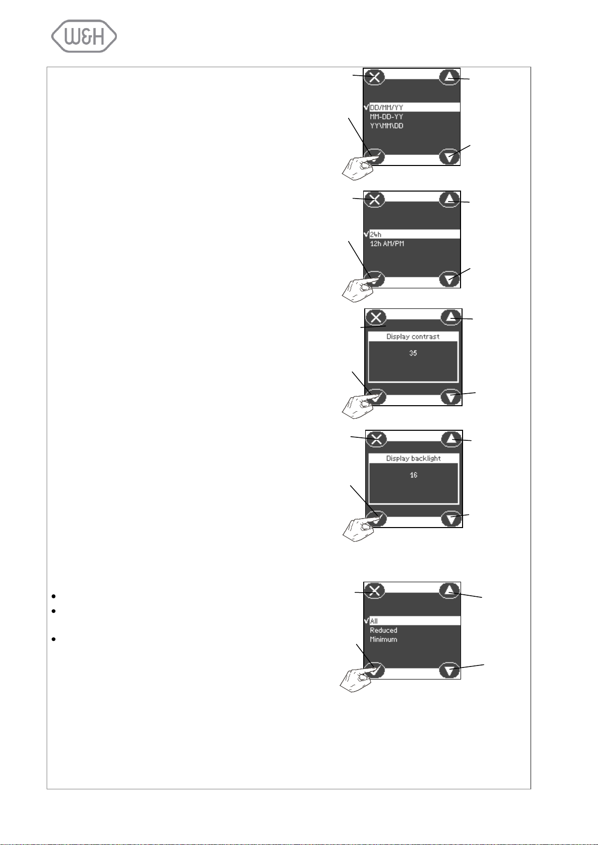
6.1.10 Date format
Use this menu to change the date format.
Press the “Scroll up” and “Scroll down” icons
to select the format. Press the “Confirm” icon
to save the selection.
6.1.11 Clock format
Use this menu to change the clock format.
Press the “Scroll up” and “Scroll down” icons
to select the format. Press the “Confirm” icon
to save the selection.
6.1.12 Display contrast
Use this menu to change the screen contrast
for a better visualization in regards to the sur-
rounding environment. Press the “Increase
contrast” and “Decrease contrast” icons to ad-
just the contrast. Press the “Confirm” icon to
save the selection.
6.1.13 Display backlight
Use this menu to adjust the screen backlight.
Press the “Increment” and “Decrement” icons
to change the setting. Press the “Confirm” icon
to save the selection.
6.1.14 Acoustic tones
Use this menu to set the amount of audible
tones the sterilizer is generating for various
procedures:
“All”: All actions come with audible tones.
“Reduced”: Most actions come with audible
tones.
“Minimum”: Only critical actions come with
audible tones (e.g., alarms, end of cycle,
etc.).
Press the “Scroll up” and “Scroll down” icons
to select the setting. Press the “Confirm“ icon
to save the setting.
Exit and return to
higher menu level
Scroll up
Scroll down
Confirm and return
to previous screen
Exit and return to
higher menu level
Scroll up
Scroll down
Confirm and return
to previous screen
Exit and return to
higher menu level
Increase
Decrease
Confirm and return
to previous screen
Exit and return to
higher menu level
Increase
Confirm and return
to previous screen
Decrease
Exit and return to
higher menu level
Scroll up
Scroll
down
Confirm and return
to previous screen
18
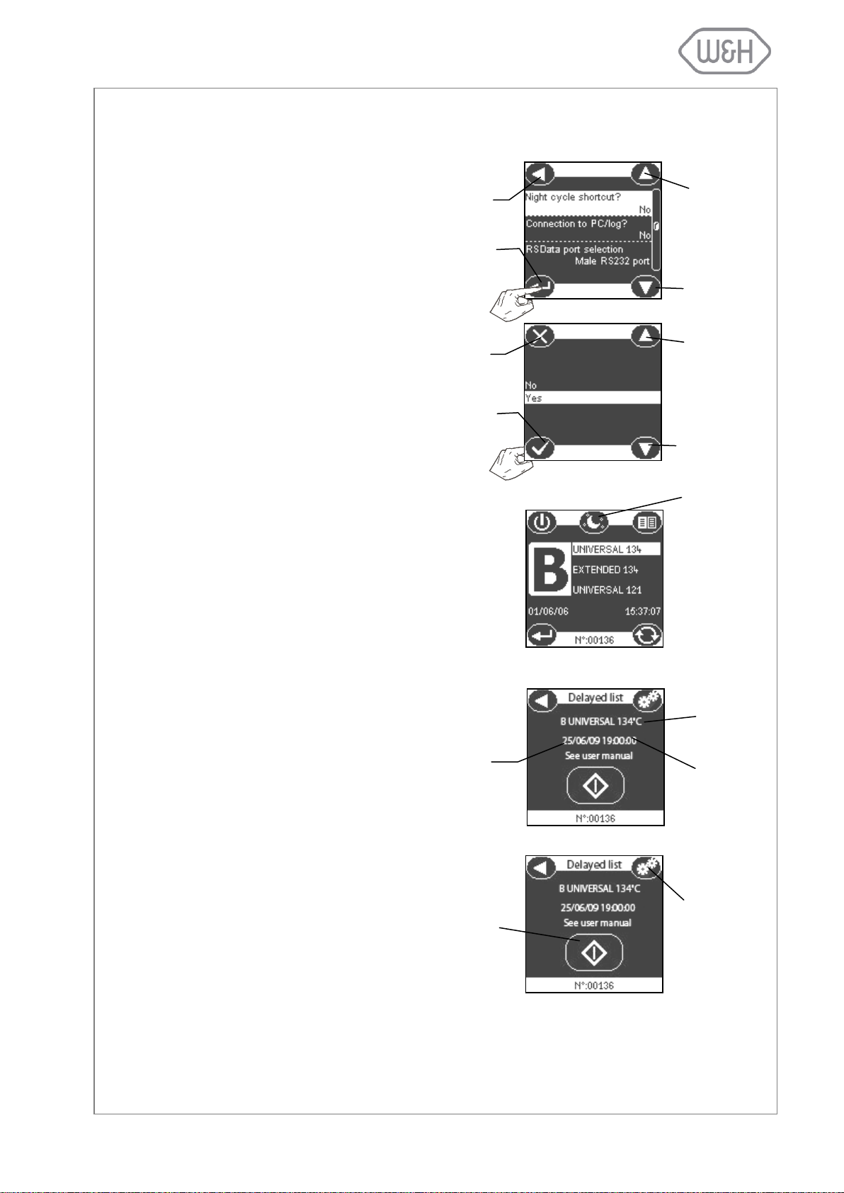
6.1.15 Night cycle shortcut
Select the “Night cycle shortcut” option by
pressing ”Scroll up” and “Scroll down”.
Press “Confirm” to enter the option.
Select “Yes” using “Scroll up” and “Scroll
down” and press “Confirm” to save the
setting.
Once you have selected the shortcut option, a shortcut icon will appear on the
main screen (cycle selection screen; see
picture to the right).
Note: The shortcut icon will only appear if
you have used the delayed cycle start
function at least once in the past.
Whenever you wish to use the delayed
cycle start function, press the shortcut to
night cycle icon. You will access a screen
showing your most recent settings for delayed cycle start cycle type and time/date.
Note: The suggested date will be set by
default to either the current day or the
next day, depending on your past programming pattern.
If you wish to modify any of the default
settings, press the “Settings” icon. This
will send you to the delayed cycle selection screens. Please refer to § 6.2 for further information.
To launch the delayed cycle, press the
“start cycle” icon.
Most recent
cycle type
Time of most
recent cycle
Current date or
date of next day
“Shortcut to
night cycle”
Scroll up
Scroll down
Exit and return to
higher menu level
Selection
confirmation
Confirm and return
to previous screen
Exit and return to
higher menu level
Scroll down
Scroll up
SETTINGS
icon; press to
enter delayed
cycle selection
screens
START Cycle
icon to launch
delayed cycle
If you frequently use the delayed cycle start option (see § 6.2) you can activate an icon on the main screen
(cycle selection screen) that will serve as a shortcut to the delayed cycle start submenu.
19

Select the “Connection to PC/Log?” option by pressing the “Scroll up” and “Scroll
down” icons. Press “Confirm” to enter the
option.
Select “Yes” using the “Scroll up” and
“Scroll down” icons and press the “Confirm” icon to save the setting.
Select the “RSDATA port selection” op-
tion by pressing the “Scroll up” and “Scroll
down” icons. Press the “Selection confir-
mation” icon to enter the option.
There are two serial ports for data transfer fitted in the back of the sterilizer. Looking at the sterilizer from the back, the
serial port on the right side is of a female
type (RS232), whereas the port on the left
is of a male type (RS232). Any of the two
ports can be used for data transfer; the
LisaWare package includes both male
and female cables. Select the serial port
you wish to allocate for data transfer us-
ing the “Scroll up” and “Scroll down” icons
and press the “Confirm” icon to save the
setting.
Scroll up
Scroll down
Exit and return to
higher menu level
Selection
confirmation
Scroll down
Scroll up
Exit and return to
higher menu level
Selection
confirmation
Scroll up
Scroll down
Selection
confirmation
Exit and return to
higher menu level
Confirm and return
to previous screen
Exit and return to
higher menu level
Scroll down
Scroll up
6.1.16 Connection to PC/Log
Use this menu if you want your sterilizer to communicate with a computer in conjunction with the LisaWare
software package. For further details please see § 4.4.
6.1.17 RSDATA port selection
Use this menu to allocate one of the rear serial ports for data transfer to your computer in conjunction with
the LisaWare software package (see § 4.4).
20
 Loading...