

Page 1

58kHz SKY-GUARD
TM
INSTALLATION
MANUAL
WG SECURITY PRODUCT INC.
3031 Tisch Way #602 San Jose, CA 95128 USA
Tel: 408-241-8000 Fax: 408-241-8082
For Tech Support In Your Country Please Visit Our Web Site
www.wgspi.com
Page 2

TABLE OF CONTENTS
SECTION ONE
OVERVIEW…………….………………………………………..……………………..…………..P1
INTRODUCTION ………...……………..…………………………………………..……………..P1
FEAT URES……………..……...………………………………………………………………......P2
APPLICATIONS………………..…………………………………………………………………..P3
P ARTS LIST …………………… ..………………………..………………………… ……….…....P4
SECTION TWO
INSTALLATION PROCEDURES………….…………….……………….……….……….….....P5
QUICK START INSTRUCTIONS ..……………………….……………………………...….…..P7
PROBLEMS..…………..…………..………………………….……………………………..…....P7
ACCESSORIES..……………..…..……………………….…….………………………..……….P7
SECTION THREE
APPENDIX (IR CONTROL KEYBOARD FUNCTION DESCRIPTION)
KEY DEFINITIONS & DEFAULT PARAMETERS TABLE …………………………….……..P8
FLOW CHART OF SUGGESTED TUNING PROCEDURES …..…………..…………..……P9
TUNING INSTRUCTIONS………………………………………………………………….…...P10
PARAMETERS CONFIGURATION …………………..………………………………….……P12
SECTION FOUR
IMPORTANT SAFEGUARDS AND REGULATORY NOTICES…………..……………….P16
Page 3
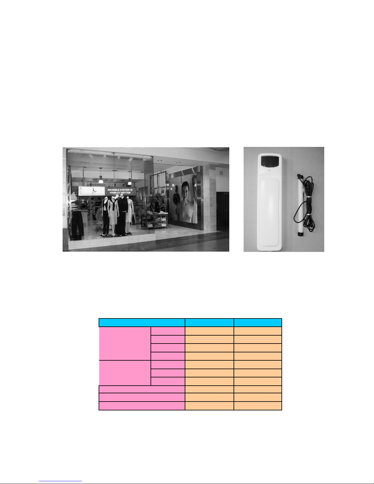
Page: 1
Overview
Introduction
Sky-Guard
TM
is an inv i sibl e system i nstall ed into a d oorf ram e or m all ent rance w al ls,
without any obtr us iv e s i de p anels or p edestals. The system eliminates the confli c ti on
between secur ity merchandise t agging and integri ty of store décor. Sky-Guard
TM
is
fully automatic with self-tuning electronics, plug and play. It is the FIRST smart
installat ion system of looping s ystems. It can be in stalled into any size of ent rance
frame wi thout the adjust m ent of s ystem . And it can als o consta ntl y chang e its p hase
to accommodate the environment that it protects.
The Sky-Guard
TM
system is software driv en EAS system that w orks in combination
with any 58KHz tag s and l abels. The s ystem’s t ransm itter s ends out 58Khz si gnals,
exciting t ag s wit hi n the detec ti on z o ne, a nd the system receiver li st ens for the uniq ue
signal t hat any 58KHz tags and labels produc e, and the sequenc e pr oduced is t hen
verified and multiplied in a fraction of a second.
Europe United States
Length 535mm 21"
Height 70mm 2.7"
Width 138mm 5.4"
Weight 10kg 10kg
Width 40mm 1.5"
Length 80mm 3.1"
Weight
200~220VAC 110VAC
58Khz 58Khz
2 meters 7 feet
System
Technical Data
Maximum Tag Detection
Active antenna
Power
Operating Frequency
Page 4

Page: 2
Features
Digital Signal Processing
The Sky-GuardTM system applies the l at est and most technical l y advanced DSP
technologies to address antitheft problems. It minimizes false alarms while
maintaining considerable detection range.
Smart Installation
Sky-GuardTM is the fir st smart installation loopi ng sys tem in the EAS industry,
which elim inates the need f or expensiv e technicians during inst allation. Due t o
a vari ety of entrance dimensi on, formal system has to be proper ly adjusted to
ensure the tr ansmitter adap tation. The Sky-Guar d
TM
is fr ee of this troubl e, as
soon as the pow er is app lied, the syst em will automatically detect the entrance
shape and tune the transmitter electronics to optimum performance, making
Sky-Guard
TM
a real plug and play looping system.
Self-Tuning El ectronics
Other manufacturers need professional technicians to tune the system to
ensure proper functioning. But once the environment condition changes, the
systems best working position changes and requires tuning again. The
Sky-Guard
TM
system, benefiting from its fully digital electronics, constantly
detects the env ironment & automaticall y adapts to any chang es. It will always
operate at its optimum performance from the beginning.
Software Driven
The Sky-GuardTM is fully digital software driven system, which allows
unprecedented flexibility especially in later versions.
System Expansion
The typi cal app licati on of the s ystem is for the entr ance of 7 feet or bel ow, but
there may be special cases requiring the protection of even wider openings
which m akes Sky-Guar d
TM
advantag eous. Unl ike ot her syst ems with addit ional
bulk size pedestals, Sky-Guard
TM
only need to add few slim active antennas
according to the w i dth of ent ra nce, m aking system exp ansion e asy, simp le and
cost-effective.
Page 5
Page: 3
Applications
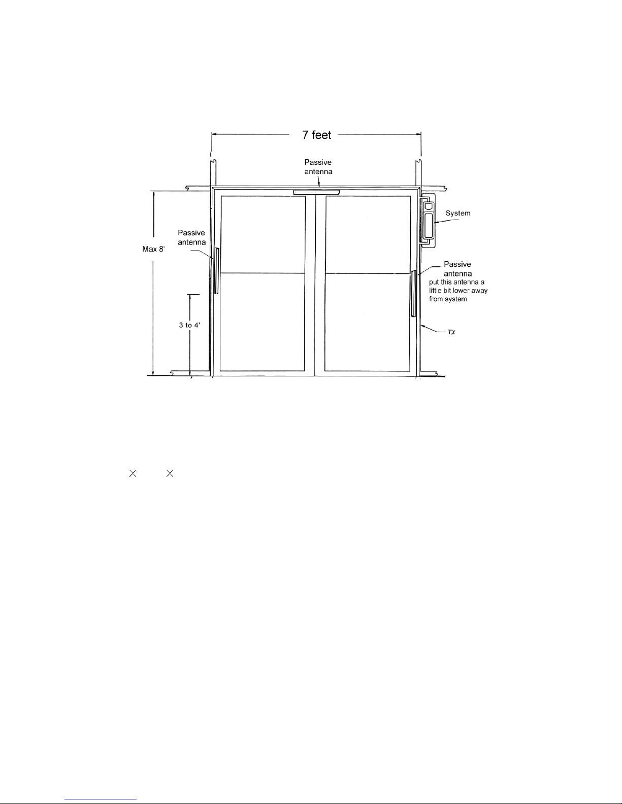
Sky-GuardTM system simple i nstallati on consis ts of the syst em measur ing 2.7” (H)
21”(L) 5.4”(W), three passive antennas 3.1” long with a width of 1.5”, and
built-in enunciator. Detection with a simple installation extends up to 7ft in all
directions within the loop with 58k hard tag. If used with labels, some more
detecting ant ennas s hall be i nstalled. The system can be m ounted on eit her side
of doorway .
The Sky-Guard
TM
can be installed close to a metal door or frame with out
decreasing the detection range, but once the material or environment around door
entry changes, the system need to be reset to adjust the inductance of
transmi tter. We als o recommend that t he when using a neon light, the s ystem i s
kept 12 f t away, if this is not possib le you can inst all our noise shi eld over the
transformer to eliminate this problem.
Page 6
Page: 4
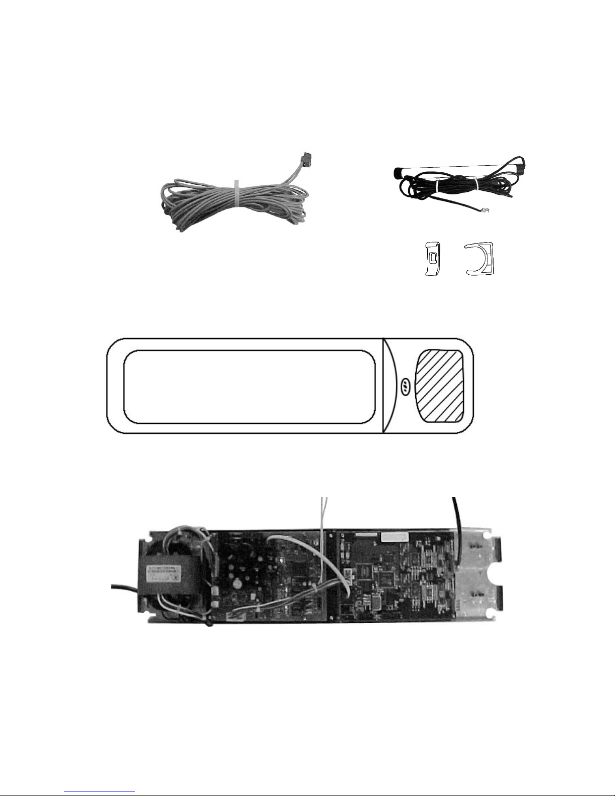
Parts List (For simple installation)
Tx loop (9 m)
Antenna holders (4
sets)
Syst em (1)
with build-in alarm indicator
Passive antenna
(3 sets)
System open picture
Page 7
Page: 5
Installation Procedures
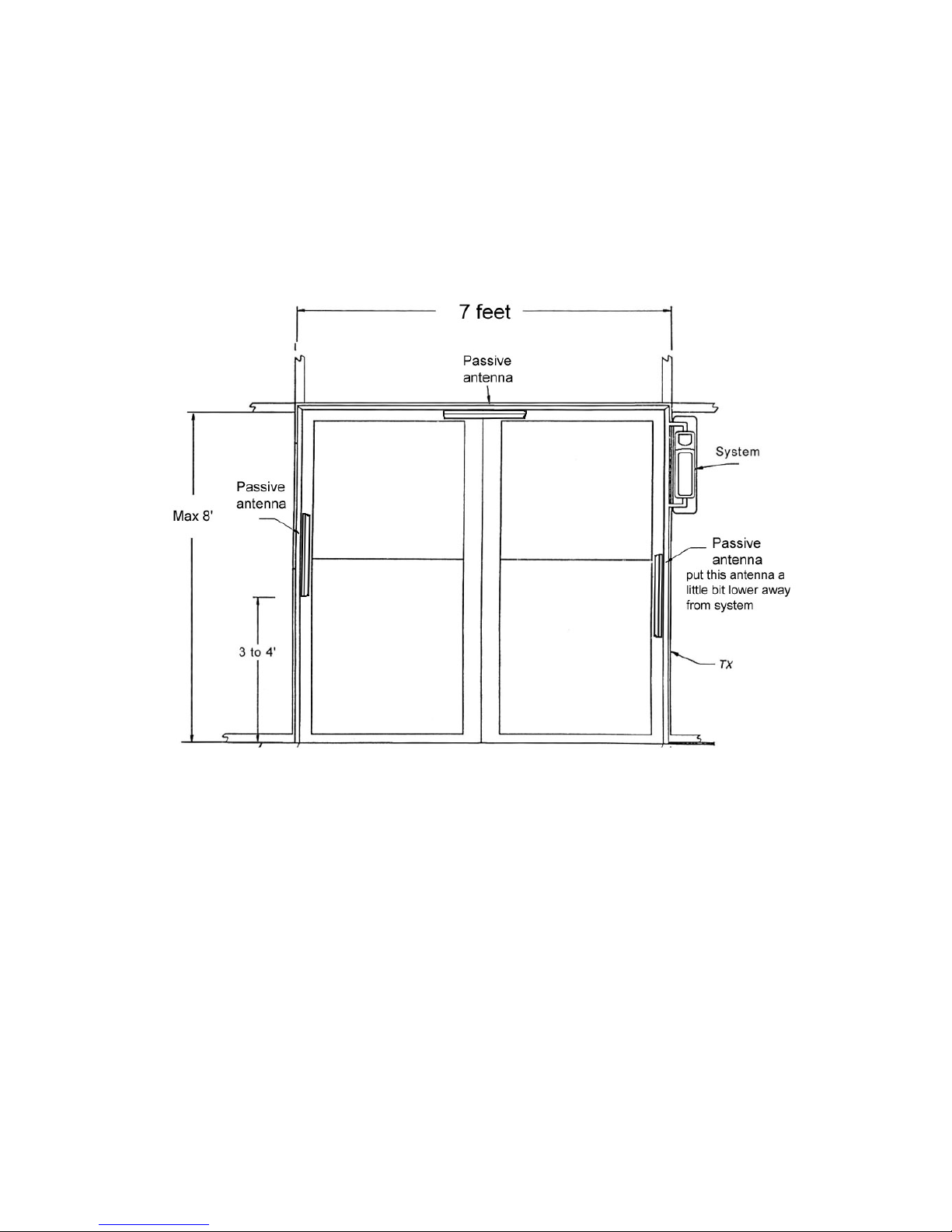
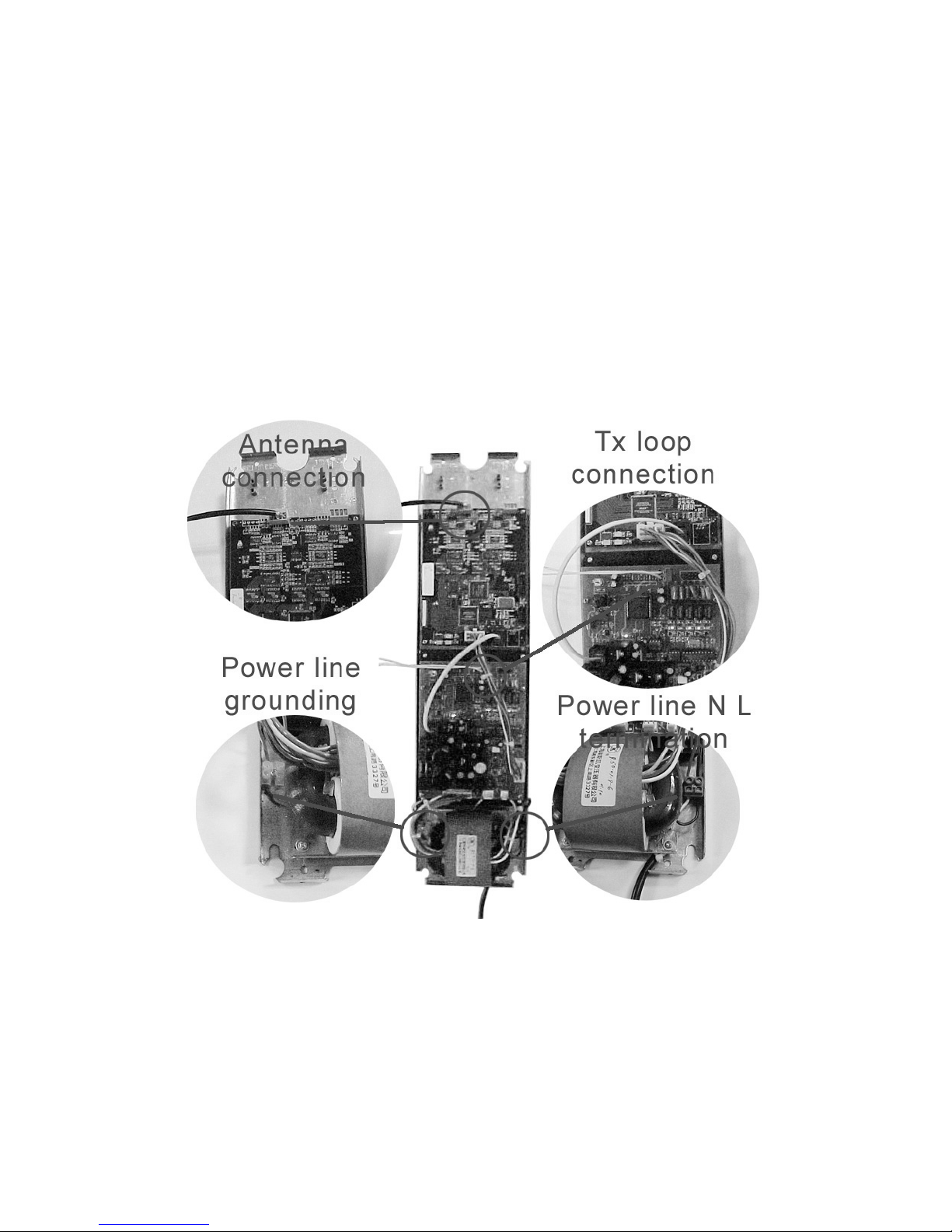
1. First loop the TX loop according to the outline of the gate frame.
2. Open the system housing , and m ount th e s ystem on the one sid e of the gat e as th e
diagram shows.
Page 8
Page: 6
3. First mount the antenna holders 3 to 4’ above the ground (two holders for every
side) , and scew the passive antennas into the doorframe.
4. Plug the antenna connections onto the system and do the same to Tx loop
connection.
5. The power line connections are ready with the system when out of box, but if
expansion of the power line is needed, the termination can be connected as the
above di agram shows. The lef t terminal i s for power li ne grounding, and t he right
terminal is for power line N and L terminations. N and L can be swapped.
6. Final ly w hen all the c onnect ions r eady, mount t he hous ing onto t he syst em and f ix it
by screwing down the screws at the upper and lower side of the system housing.
Page 9

Page: 7
Quick Start Instructions
When all procedures of installation finished and the power applied on, the system
automatically enters the tra nsmitter self-configuration condition. In this stage, you can
hear the buzzer beeps regularly with a sequence of medium intervals. When the
self-configuration accomplished, three beeps of short term intervals indicate that the
system is ready for tag detections.
Problems
If you ensur e ev ery st ep of the i nstall ation is pr oper , all the co nnecti ons are cor rec t, a nd
the system still malf unctions or does not wor k w i th sati s f ac tor y sens i ti vity, pl eas e cal l our
technical support number (408-530-8070)
Accessories
A noise shield is available to cover the electronic transformer. This eliminates the
problem of noise from the proximity of Neon Lighting.
Page 10
Page: 8
Appendix (IR control keyboard function description)
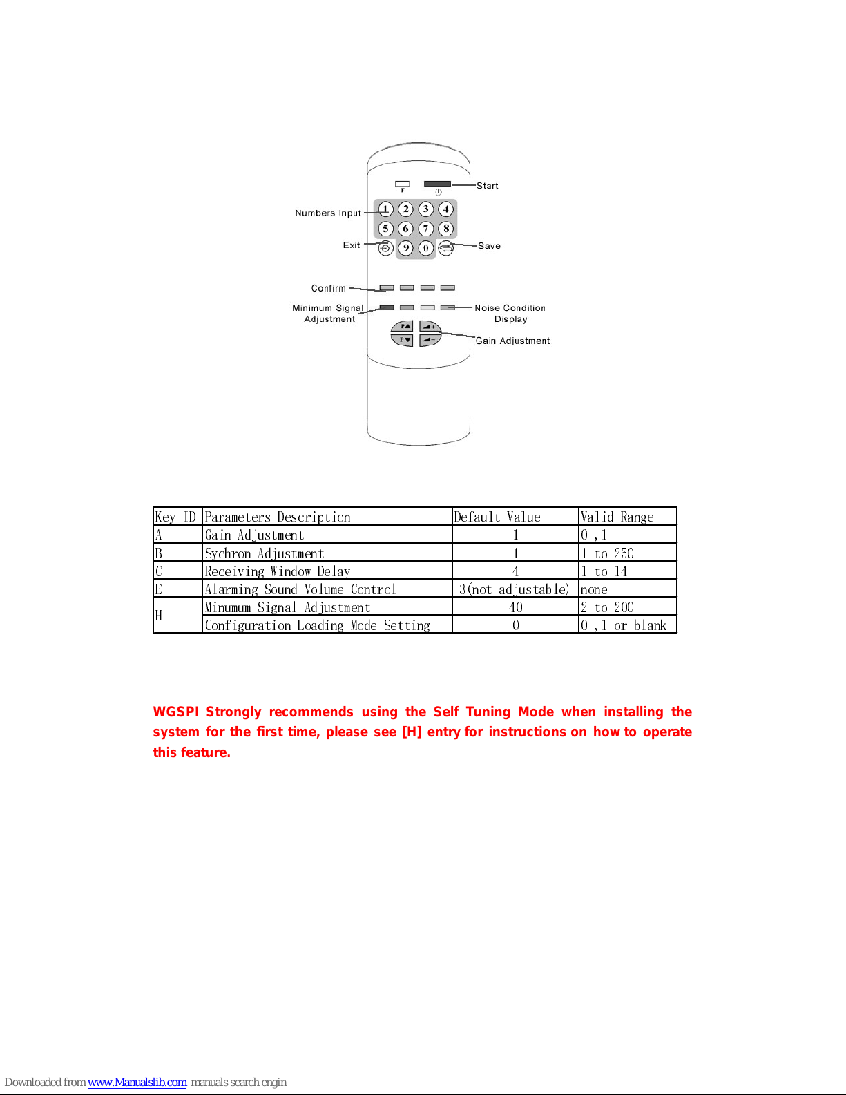
Default Parameters Table
.H\ ,' 3DUDPHWHUV 'HVFULSWLRQ 'HIDXOW 9DOXH 9DOLG 5DQJH
$ *DLQ $GMXVWPHQW
% 6\FKURQ $GMXVWP HQW WR
& 5HFHLYLQJ :LQGR Z 'HOD\ WR
( $ODUPLQJ 6RXQG 9RO XPH &RQWURO QRW DGMXVWDEOH QRQH
0LQXPXP 6LJQDO $GMXVWPHQW WR
&RQILJXUDWL RQ /RDGLQJ 0RGH 6HWWLQJ RU EODQN
+
WGSPI Strongly recommends using the Self Tuning Mode when installing the
system for the first time, please see [H] entry for instructions on how to operate
this feature.
Page 11
Page: 9
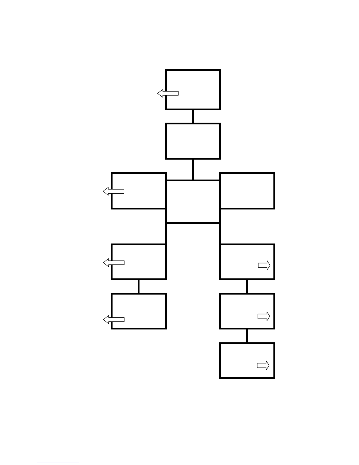
FLOW CHART OF SUGGESTED TUNING PROCEDURES
System Defaut
Weak Performance & or False alarms
from your systems or theirs
Check Noise "D"
D B
Alternate between D1-D6 & B to
get most favorable parameters
( Low Noise Lev el )
If noise is less than 80 If noise is higher than 80
H A
If OK - You are done If noise is higher
1/2 of new noise or less=va lue than 80 Adjust Gain
increase slightly if False Alarms to 0
IF Not Acceptable
Check Noise Value and
Sensitivity of the System .
C H
If syst em is picking wel l,
Adjust until sensitive enough Your'e Done, If weak
then increase until stable adjust H to approximately
1/2 of Noise Level, if false
alrarms adjust slightly
Upward
C
Adjust from C6 to C1
until system is working
well. Than adjust Up
until system is stable
*Always Watch the system for about an Hour to ensure that you have chosen stable paramaters
Page 12

Page: 10
Tuning Instructions
1. Fi rstl y, op en system s one by one if there are m ultiple syst ems w orks together. Mak e
sure ever y system does not i nterr up t another i f anot her is under sel f detecti on m ode.
(see entry H)
2. If the system is less sensitive,
Firstl y, adjust Minimum Signal Adj ustment f igures by a decrem ent of 20. The defaul t
number is 40. Please decrease the parameters by a step of 20 until the system
reaches satisfactory sensitivity.
Next but not im portant is to rai se Gain Adjustment from 0(low) to 1(high), bec ause
usually the default settings is 1 already.
3. If the system gives false alarms,
Firstl y, shut down all the ot her system s ( includi ng all the pos sibl e noise sour ce such
as lights electronic equipment and etc.) If it doesn’t stop this system from false
alarming, please follow the above two methods in an inverse way. A. Increase
Minim um Sig nal Adj ust ment by an i nc r ement of 20 . The r ang e i s from 20 to 200. B.
Lower Gain Adjustment from 1(high) to 0(low).
Secondly, if all the other s ystems work s properly except that tur ning on this system
renders ot hers f al se alar m or s hut dow n, p leas e switch the L a nd N term i nals on t he
power cord(see Power Cord Notice in above sections).
4. If any efforts followed by the above methods failed to eliminate the system false
alarmi ng or fals e alarm s ar e stopp ed but s ystem det ection r ange dr op s bel ow 6 feet ,
please call the number in the first page to ask for our help.
Page 13
Page: 11
Parameters Configuration
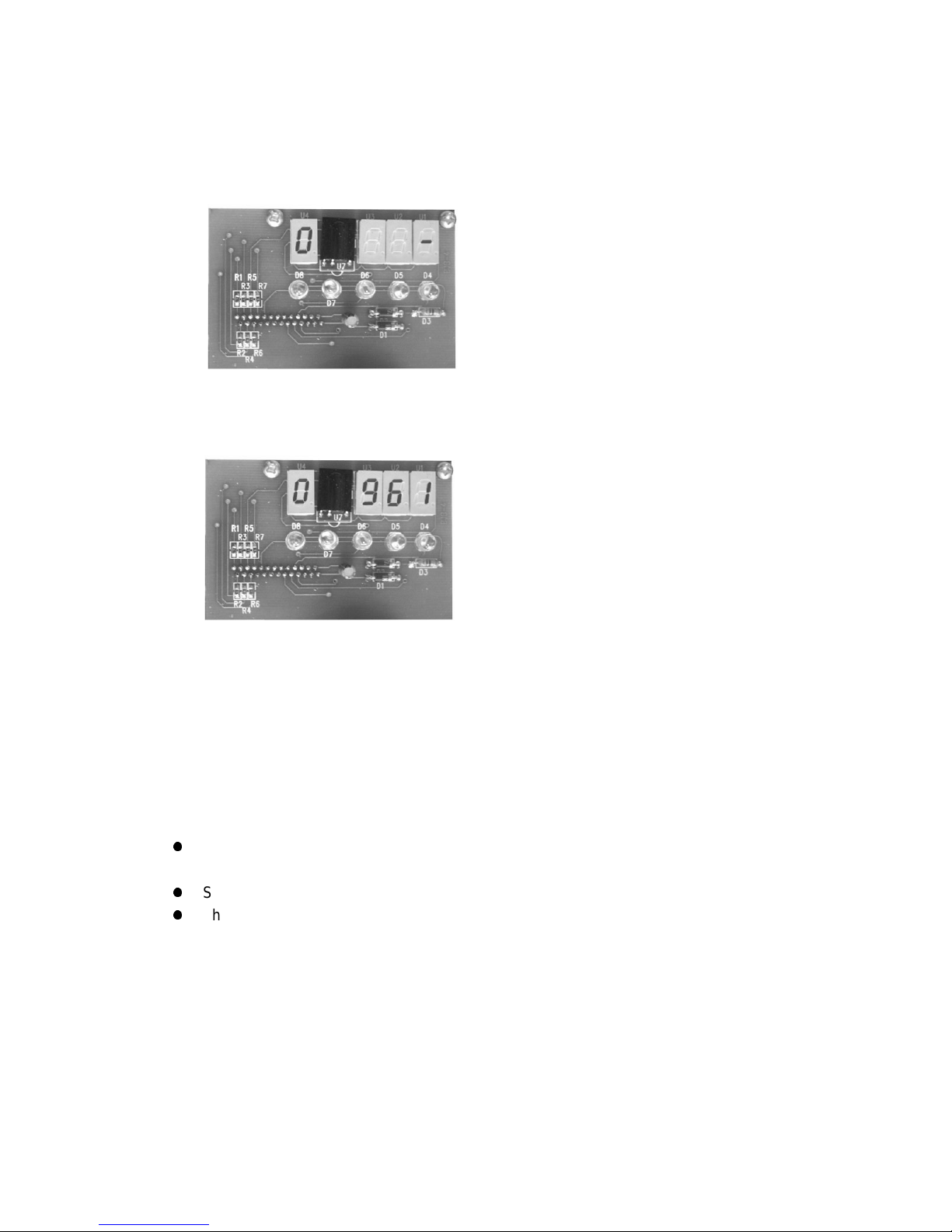
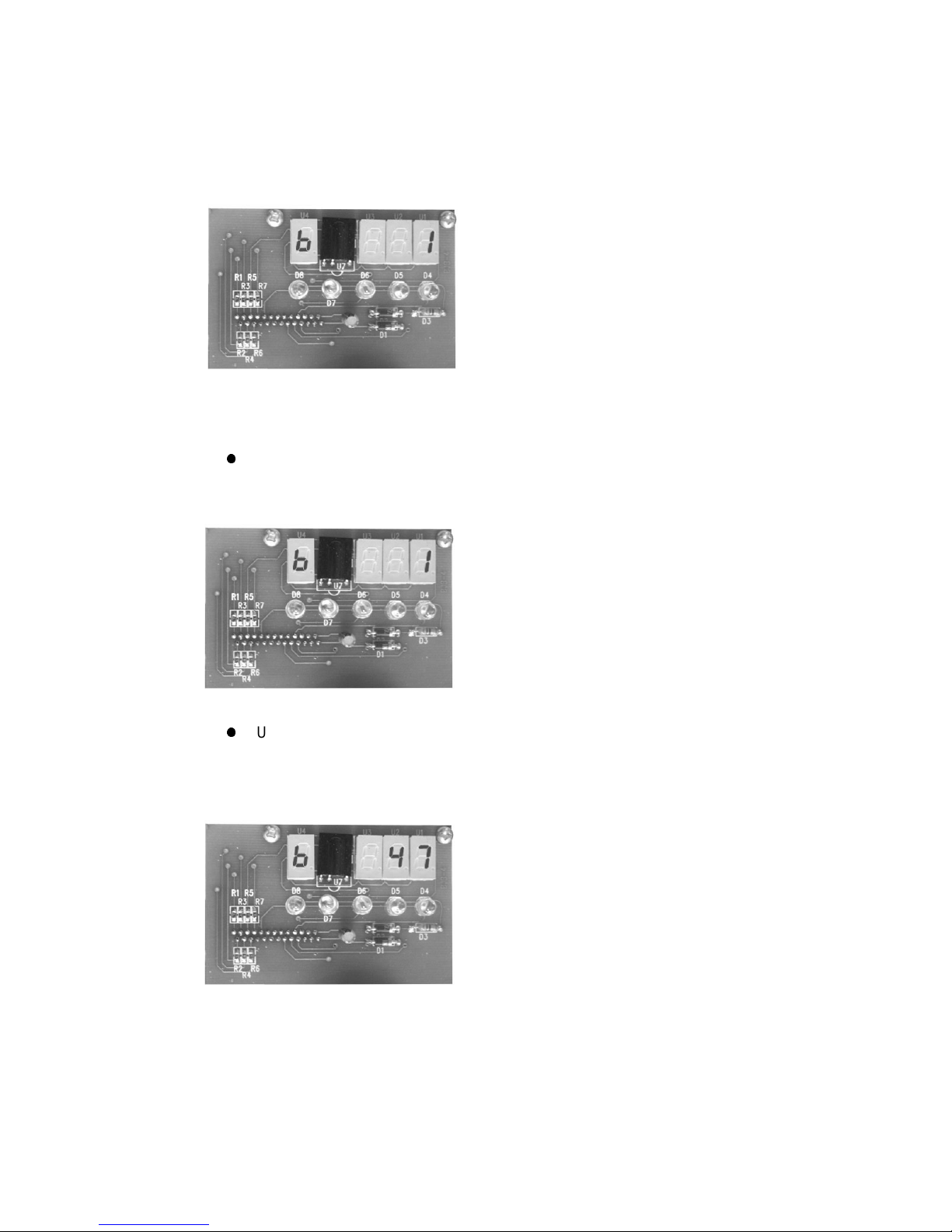
1. press “start” button to initiate the control
when panel shows the following state, initiation is ready.
Fig. 1
2. Press password “961”
Fig. 2
3. Press “confirm” button
Then enter the control parameters input state.
There usually are three steps in parameters input.
z
Firstly, select the parameter type, like Gain Adjustment, Sychron Adjustment or Noise
Condition Display;
z
Secondly , input the numbers within a valid range;
z
Thirdly, press “confirm” button.
Page 14
Page: 12
Parameter Type Description
A. Gain Adjustment (range: 0-1)
There are two choices here, input 1 to select high gain, 0 to low gain.
Fig. 3
B. Sychron Adjustment (range: 1-250; increment: 1)
z
It is the time from zero crossing point to the start point of transm itting burst.
This is usu al l y se t f or multip l e s ystems worki ng on a di f f er ent p ow er l i ne w i th
phase problem. The range is 1~250, each stands for 34u seconds.
Fig. 4.1
z
Under this entry, you can also see the different noise condition (from the light
segment display and number indication) at a different phase when the
adjustment goes on. It will help you to select a relative “clean” phase
environment to set the system on.
Fig. 4.2
Page 15
Page: 13
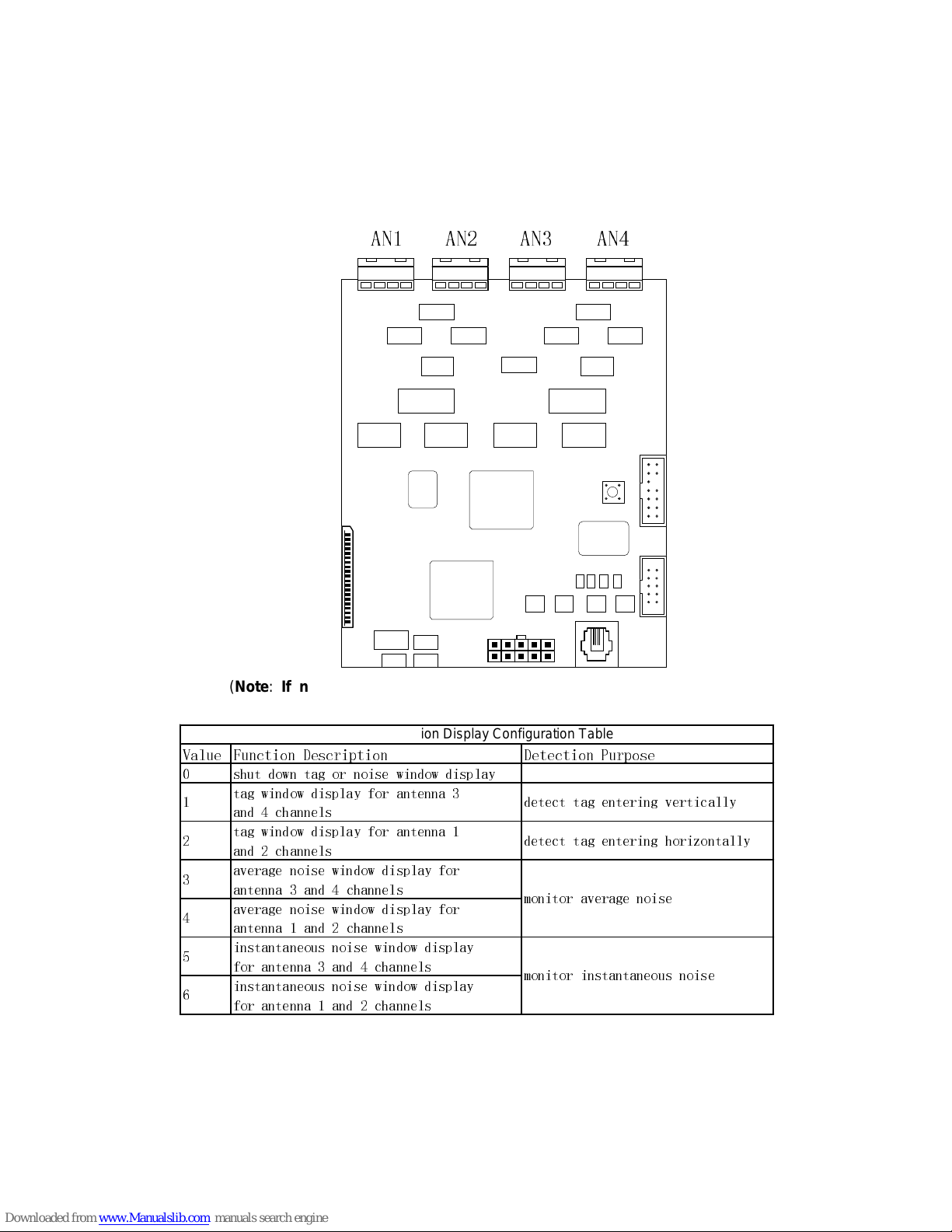
C. Noise Condition Display (range: 0-3)
The LEDs show signal or noise level by figures while the light segments bar
shows the level by the number of segments lit.
Select diff erent par ameter to choose t he corr esp ondi ng antenna c hann el to v i ew
tag and noise condition.
$1 $1 $1 $1
(Note: If noise condition display is activated, alarm will be deactivated
unless you input 0 to shut down the display)
9DOXH )XQFWLRQ 'HVFULSWLRQ 'HWHFWLRQ 3XUSRVH
VKXW GRZQ WDJ RU QRLVH ZLQGRZ GLVSOD\
WDJ ZLQGRZ GLVSOD\ IRU DQWHQQD
DQG FKDQQHOV
WDJ ZLQGRZ GLVSOD\ IRU DQWHQQD
DQG FKDQQHOV
DYHUDJH QRLVH ZLQGRZ GLVSOD\ IRU
DQWHQQD DQG FKDQQHOV
DYHUDJH QRLVH ZLQGRZ GLVSOD\ IRU
DQWHQQD DQG FKDQQHOV
LQVWDQWDQHRXV QRLVH ZLQGRZ GLVSOD\
IRU DQWHQQD DQG FKDQQHOV
LQVWDQWDQHRXV QRLVH ZLQGRZ GLVSOD\
IRU DQWHQQD DQG FKDQQHOV
GHWHFW WDJ HQWHULQJ YHUWLFDOO\
GHWHFW WDJ HQWHULQJ KRUL]RQWDOO\
PRQLWRU DYHUDJH QRLVH
PRQLWRU LQVWDQWDQHRXV QRLVH
Noise Condition Display Configuration Table
Page 16
Page: 14
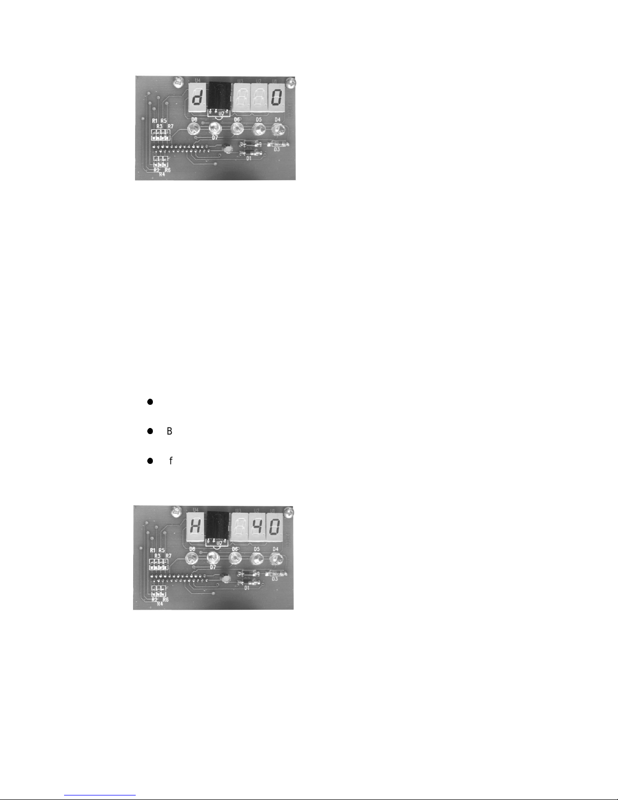
Fig. 6
H. Minimum Signal Adjustment
1. Minimum Signal Adjustment (suggested increment : 20; valid range: 2-200)
Change this f i gure to admit m i nimum signal am pl i t ude, i n another word
any signal smaller than the level here will be ignored.
Decreasing the number will increase the sensitivity of system but also at
the risk of false alarming.
Vise ver s a, i nc r eas i ng i t w il l l ow er dow n the s ensi t i vity to over c ome the
unexpected false alarming caused by uncontrollable environment noise.
2. Configuration Loading Mode Setting (range: 0-1)
Also under this setting entry, there are three modes of system
configuration loading.
z
Inputting 1 will set the system to power on self-detection mode in which
system will automatically configure all the parameters.
z
By inputting 0, system will load the default parameters from Flash ROM. (See
the default parameters table)
z
If this parameter is bigger than 2(use as Minimum Signal Adjustment), system
will load the latest saved parameters.
Note: Default parameters are NOT equivalent to the latest saved parameters.
Fig. 8
Page 17
Page: 15
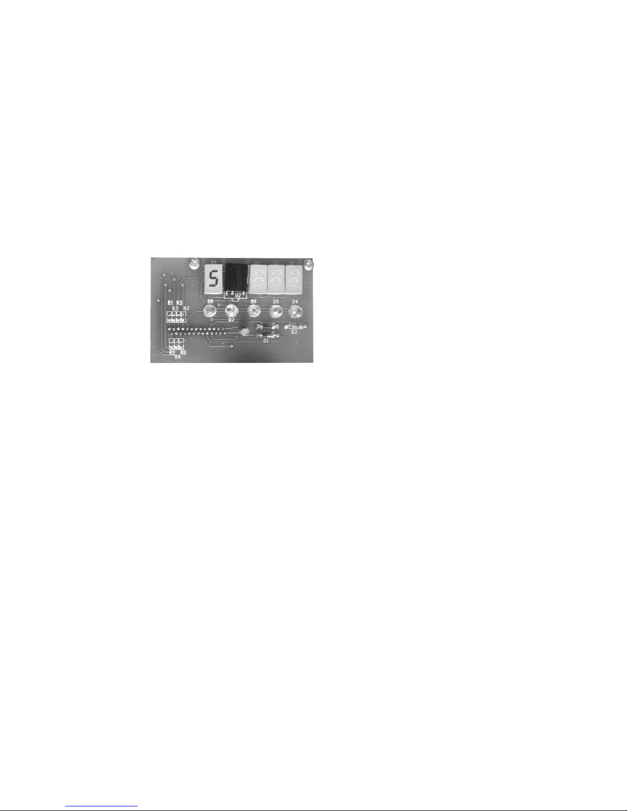
Exit button
This button will return control box to last state.
Save button
This button will save all parameters to flash ROM, so when power shut down
the parameters will not be lost.
After press this button, you should press “confirm” button to confirm saving.
Notice: But any adjustment of H as 0 (default parameters loading mode) or 1
(self-detection mode) will deactivate the application of the saved
parameters.
Fig. 9
Page 18
Page: 16
Information on the following pages provides important safety
guidelines for both Operator and Service Personnel. Specific
warnings and cautions will be found throughout the manual
where they apply, but may not appear here. Please read and
follow the important safety information, noting especially
those ins tr uct ions related to r i sk o f fire, electric s ho c k or i nj ury
to persons.
WARNING
Any instructions in this manual that require opening the
equipment cover or enclosure are for use by qualified service
personnel only. To reduce the risk of electric shock, do not
perform any servicing other than that contained in the
operating instructions unless you are qualified to do so.
Symbols an d Th eir Meanings
The exclamation point within an equilateral triangle alerts
the user to the presence of important operating and
maintenance (servicing) instructions in the literature
accompanying the equipment.
The fuse symbol indicates that the fuse referenced in the
text must be replaced with on e having the ratings indicated.
Important Safeguards and
Regulatory Notices
Page 19

Page: 17
Danger
Electrical potential is still applied to some internal
comp onents even when the power sw itch/b reaker is in th e
off position. To prevent electrical shock when working on
this equipment, disconnect the AC line cord from the AC
source before working on any internal components.
A residual voltage may be present immediately after
unplugging the system due to slow discharge of large
power supply capacitors. Wait 30 seconds to allow
capacitors to discharge before working on the system.
Warnings
Heed all warnings on the unit and in the operating
instructions.
Do not use this equipment in or near water.
Disconnect AC power before installing any options.
The attachment plug receptacles in the vicinity of the
equipment are all to be of a grounding type, and the
equipment grounding conductors serving these are to be
connected to earth ground at the service equipm e nt.
This equipment is grounded through the grounding
conductor of the power cord. To avoid electrical shock,
connect the power cord to the equipment and plug it into a
properly wired receptacle before connecting the equipment
inputs and outputs.
Route power cords and other cables so that they are not
likely to be damaged.
Do not wear hand jewelry or watches when troubleshooting
high current circuits, such as the power supplies.
During installation, do not use the door handles or front
panels to lift the equipment as they may open abruptly and
injure you.
Page 20

Page: 18
To avoid fire hazard, use only components of the specified
type, voltage and current rating as referenced in the
appropriate parts list.
Always refer fuse replacement to qualified service
personnel.
To avoid explosion, do not operate this equipment in an
explosive atmosphere unless it has been specifically
certified for such operation.
Have qualified personnel perform safety checks after any
completed service.
Risk of electric shock is present. A grounded circuit
conductor (neutral) is provided with over current protection.
Test all components before touching.
Cautions
To prevent damage to equipment when replacing fuses,
locate and correct the trouble that caused the fuse to blow
before applying power.
Verify that all power supply lights are off before removing
the power supply or servicing equipment.
Use only specified replacement parts.
Leave the base of the syste m clear for air exhaust cooling
and to allow room for cabling. Slots and openings in the
system are provided for ventilation. Do not block them.
To prevent damage to this equipment read the instructions
in this document for proper inpu t voltage range s election.
Circuit boards in this equipment are densely populated with
surface mount and ASIC components. Special tools and
techniques are required to safely and effectively
troubleshoot and repair modules that use SMT or ASIC
components. For this reaso n, service and repai r o f products
incorporating surface mount technology are supported only
on a module exchange basis. Customers should not
Page 21
Page: 19
attempt to troubleshoot or repair modules that contain SMT
components. It assumes no liability for damage caused by
unauthorized repairs. This applies to both in- and
out-of-war r an ty products.
Power Cord Notices
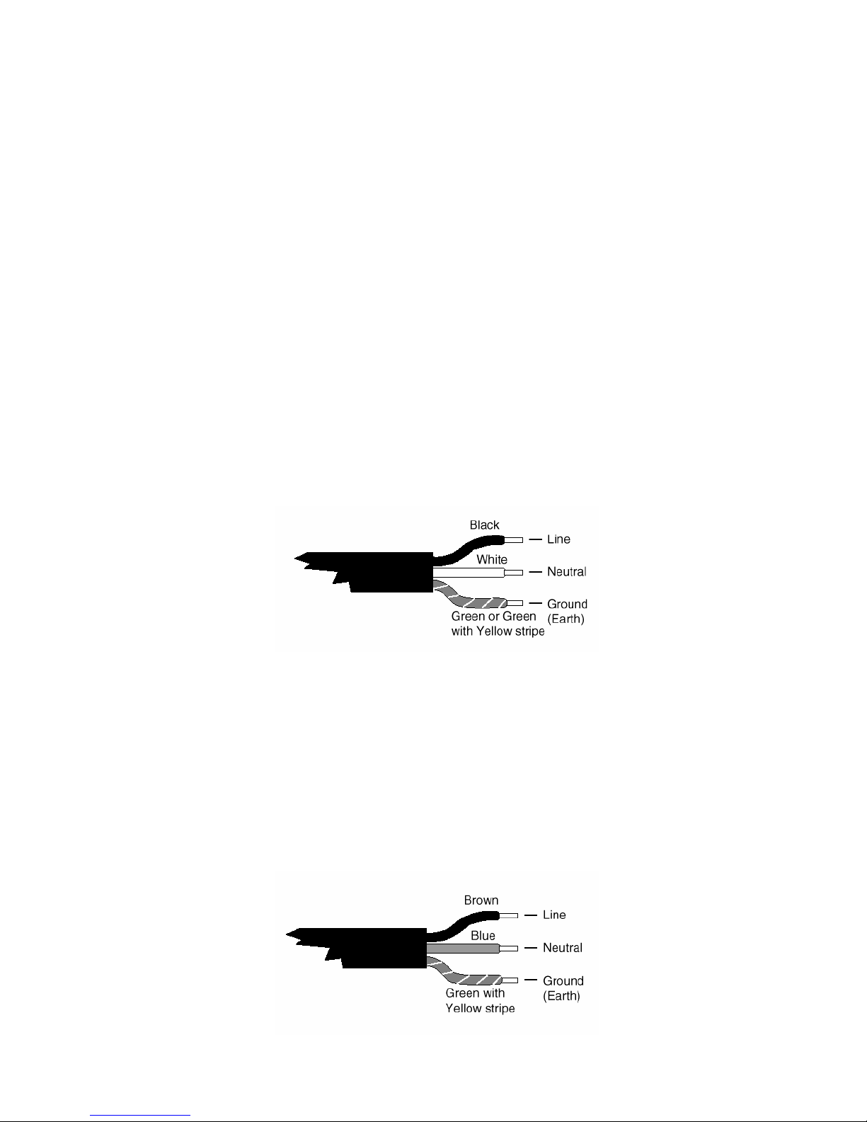
North American Power Supply Cords
This equipment is supplied with an external power line at
one end and a molded receptacle terminal block at the
other end. Conductors are color coded white (neutral),
black (line) and green or green/yellow (ground).
Operatio n o f this equipment at voltages ex c ee di ng 130 VAC
will require power supply cords which comply with NEMA
configurations.
International Power Supply Cord
This equipment is supplied with an external power line at
one end and a molded receptacle terminal block at the
other end. Conductors are CEE color coded—light blue
(neutral) , brown (line) and gr ee n/yellow (groun d) . Oth er I EC
320 C-13 type power supply cords can be used if they
comply with the safet y regulations of the country in which
they are installed.
Page 22

Page: 20
Before You Install
Introduction
Congratulations on your purchase of one of the f inest EAS
systems on the market. This is the Installation Instructions
manual.
Receiving Inspection
Inspect all shipping containers for any signs of damage. If
any is found, notify the shipping company. If there is no
obvious damage, continue with the unpacking instructions.
Unpacking Instructions
Place the containers on a flat level surface with enough
room to move the container around as needed. Remove all
the remaining manuals and the Floppy Disk software set.
Compare the manuals against the Inventory sheet and
make a note o f any dis cr epancies.
Carefully remove the contents of container and place on a
flat level surface. Compare the contents with the Part List to
ensure that there no missing items. Make a note of any
discrepancies.
Equipment Inspection
Inspect all equipment for damage. Items to specifically
check, and damage to look for, are listed below:
All connectors for bent or broken pins
Cables for cri m p ed or broken wires
Plastic housing for any obvious signs of damage
If any damage is found, contact Customer Service at the
telephone number in the f ront of this manual. If any item is
damaged, DO NOT make any power or signal connections
to the unit unless otherwise advised to do so by Customer
Page 23

Page: 21
Service.
If there are any discrepancies between the Manual Set
Inventory sheet and the manuals received, or between the
Packing List and items received, contact Customer Service
at the telephone number at the front of this manual. If there
are no discrepancies and either no damage, or
GVG-advised correction action is made, continue with this
manual.
Facility Checklist
The following checklist is a synopsis of information found in
the appropriate Installation Planning Guide. The Planning
Guide should be referred to for detailed site preparation
information.
Ensur e that there ar e suffic ient AC power outlets of the
required 3-prong grounded type and amp rating for the
intended eq ui pment.
 Loading...