

Page 1
PARTS LIST
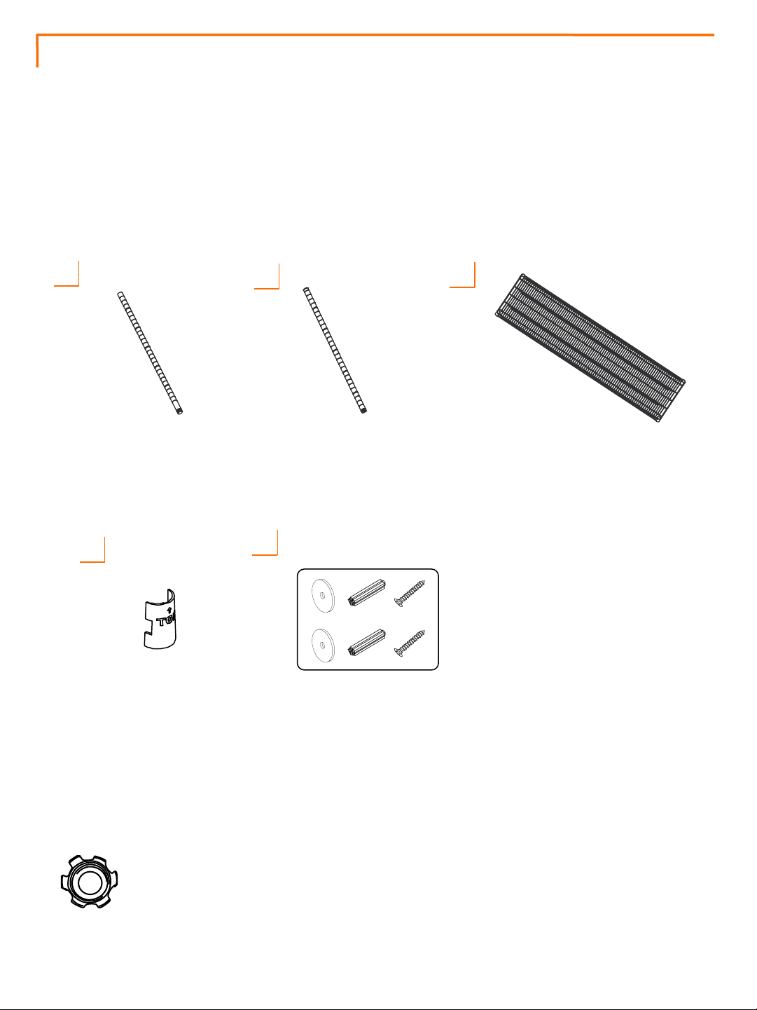
Your 72"x24"x72" Wire Shelving Rack should include the following parts. Please inspect box contents to
ensure you have received all components.
You will NOT need additional tools for assembly.
A
BOTTOM POLE (4)
Threaded Insert (4) and
Feet Leveler (4)
pre-installed
D
B C
SHELF (5)TOP POLE (4)
End Cap (4) and
pole connector (4)
pre-installed
E
SLIP SLEEVE
(40) + (2) extra
1
ANTI-TIP
HARDWARE
PACK (1)
Note: The black circular plastic spacers in between Shelves are used only for packaging
purposes. They are NOT needed. Please discard.
Page 2
ASSEMBLY INSTRUCTIONS
STEP 1
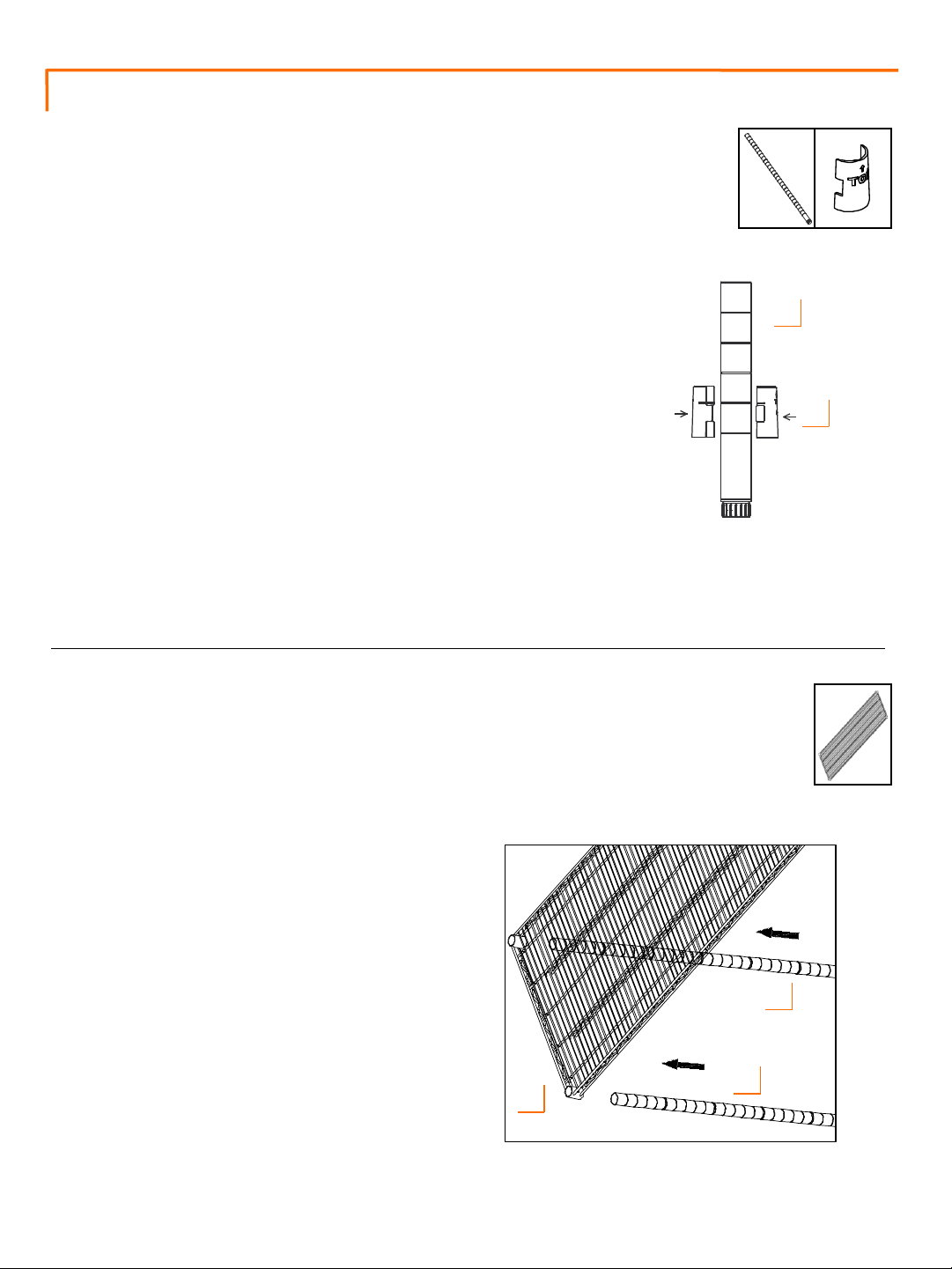
For easiest assembly, do not attach TOP POLES (B) and BOTTOM POLES
(A) until instructed. Once connected, these will be posts for the rack.
Note that POLES (A+B) have slight horizontal line indentations at 1”
intervals. Each SLIP SLEEVE (D) has raised horizontal lines inside
designed to lock them in place on POLES (A+B).
On BOTTOM POLE (A), place one pair of SLIP SLEEVES (D) at desired
height no higher than 3rd indentation from bottom. Make sure arrow
faces up and word “TOP” is right side up.
Slide pair of SLIP SLEEVES (D) until you hear a click to confirm the pair
is locked onto BOTTOM POLE (A). Do this for each BOTTOM POLE (A)
and make sure height is identical for each BOTTOM POLE (A). Do NOT
place more than one pair on each pole at a time.
Note: There will be a very small gap in-between two locked SLIP SLEEVES (D)—this is normal.
A (4) D (8)
A
D
STEP 2
Place SHELF (C) on its side and slide each
BOTTOM POLE (A) through each corner
cylinder on SHELF (C). Make sure SHELF (C)
corner cylinders are positioned over SLIP
SLEEVES (D).
Stand the unit upright.
Note:
• Level side of SHELF (C) is TOP side ( PRO
logo on corner cylinders should be rightside up.)
• Use a rubber mallet, if needed, to secure
SHELF (C).
C (1)
A
A
C
2
Page 3
ASSEMBLY INSTRUCTIONS
STEP 3
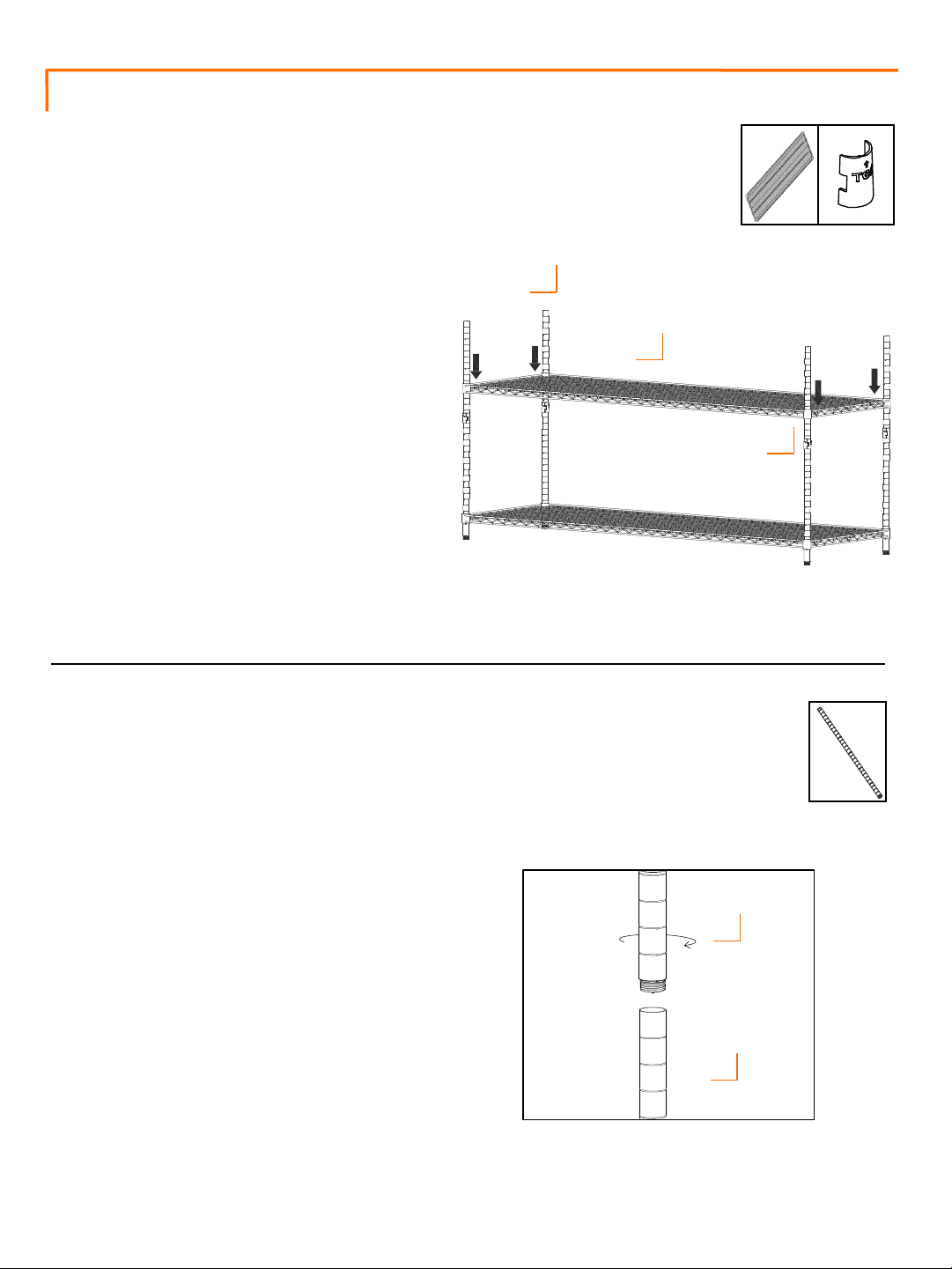
On BOTTOM POLE (A), place 1 pair of SLIP
SLEEVES (D) at desired height. Make sure
arrow faces up and word “TOP” is right
side up. Do this for each BOTTOM POLE
(A), and make sure height is identical for
each BOTTOM POLE (A).
Lower SHELF (C) over each BOTTOM POLE
(A) so corner cylinders of SHELF (C) are
positioned over SLIP SLEEVES (D).
Note:
• Shelves are adjustable in 1” increments
and can be placed as needed to best fit
storage needs.
• Use a rubber mallet, if needed, to
secure SHELF (C).
C (1)
A
C
D
D (8)
STEP 4
Screw TOP POLE (B) into BOTTOM POLE (A).
Repeat for each remaining TOP POLE (B).
Note: Top of each TOP POLE (B) is indicated
by a BLACK END CAP.
3
B (4)
B
A
Page 4
ASSEMBLY INSTRUCTIONS
STEP 5
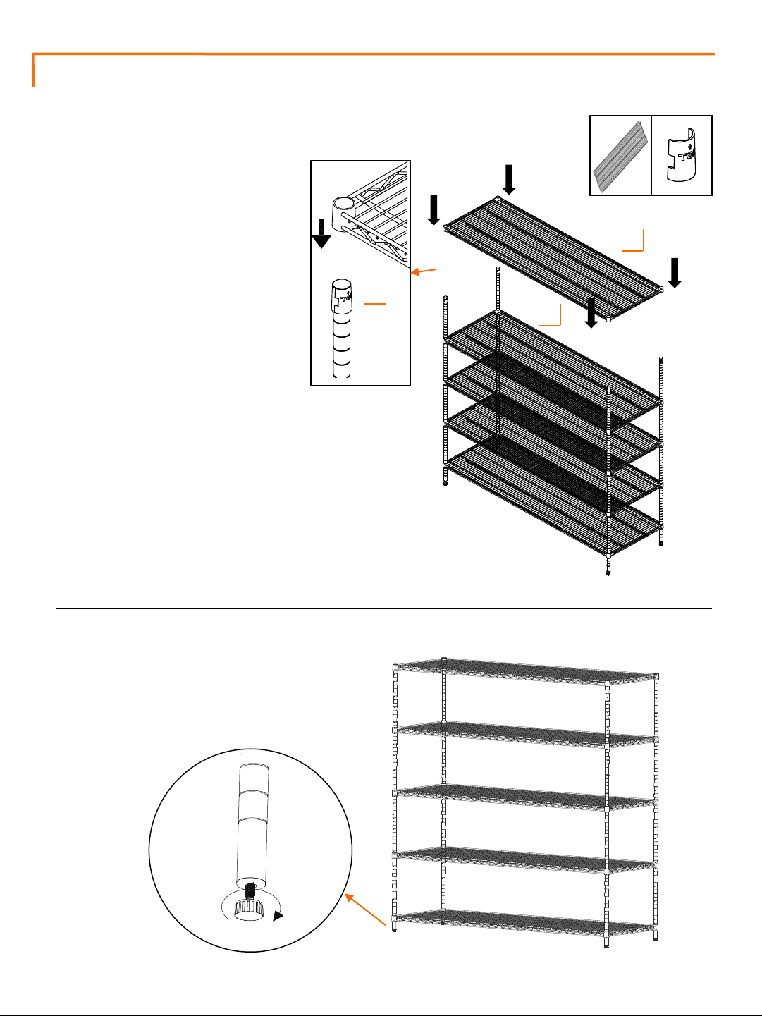
Repeat Step 3 to install other
SHELVES (C) as desired.
C (3)
D (24)
Note:
• Shelves are adjustable in 1”
increments and can be placed
as needed to best fit storage
needs.
• Use a rubber mallet, if needed,
to secure SHELVES (C).
C
D
C
STEP 6
Adjust FEET LEVELERS as needed to ensure
shelving rack is level.
4
Page 5
ASSEMBLY INSTRUCTIONS
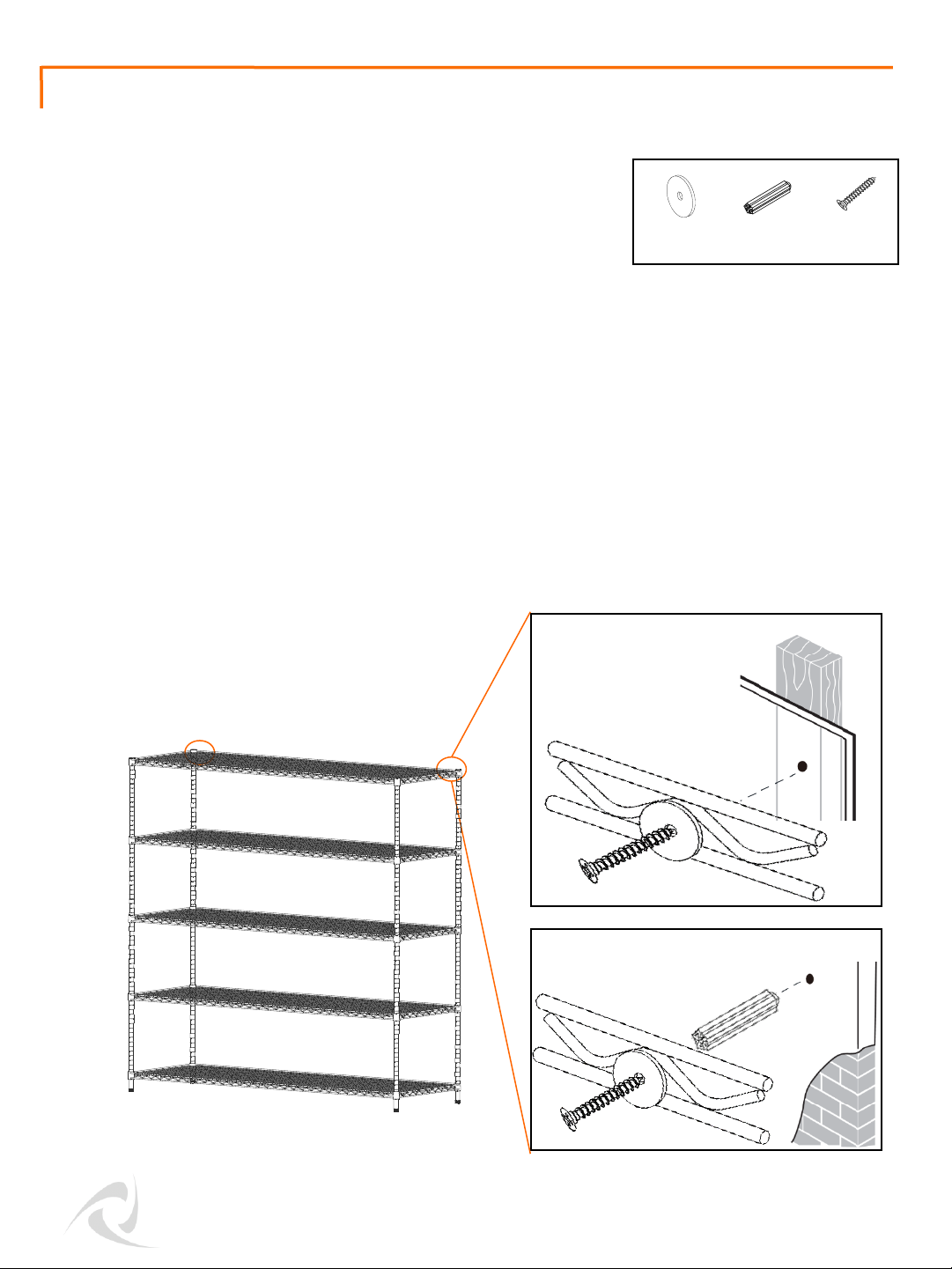
Anti-tip Hardware Installation
ANTI-TIP HARDWARE PACK (E) is used to protect against
accidental tipping – especially due to curious children.
On Wood Stud
Determine wood stud location and mark it on wall, level with topmost shelf. Do this on two different
studs along top shelf.
Place Shelving Rack into position.
Insert Screw through Washer and backside frame of top shelf as shown. Fasten Screw tightly into stud.
Do this for each stud that was marked out.
On Brick/Concrete
Mark out two separate locations on wall, level with topmost shelf.
With a 1/4” drill bit, drill a hole 1-1/4” deep at each marked location. Push Anchors flush into each hole.
Place Shelving Rack into position.
Insert Screw through Washer and backside frame of top shelf as shown. Fasten Screw tightly into
Anchor. Do this on both Anchors that were placed in wall.
(2) (2) (2)
E (1)
5
 Loading...