

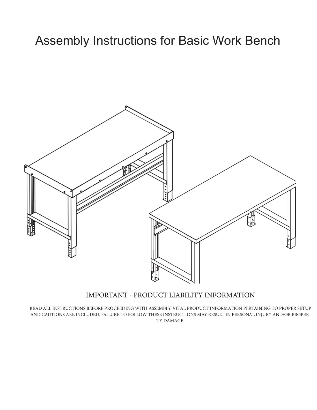
Page 1
Page 2
Basic Work Bench
1
~
2
3
Work Bench with an All-Wood Top
4
7
6
5
3
2
1
4
5
7
6
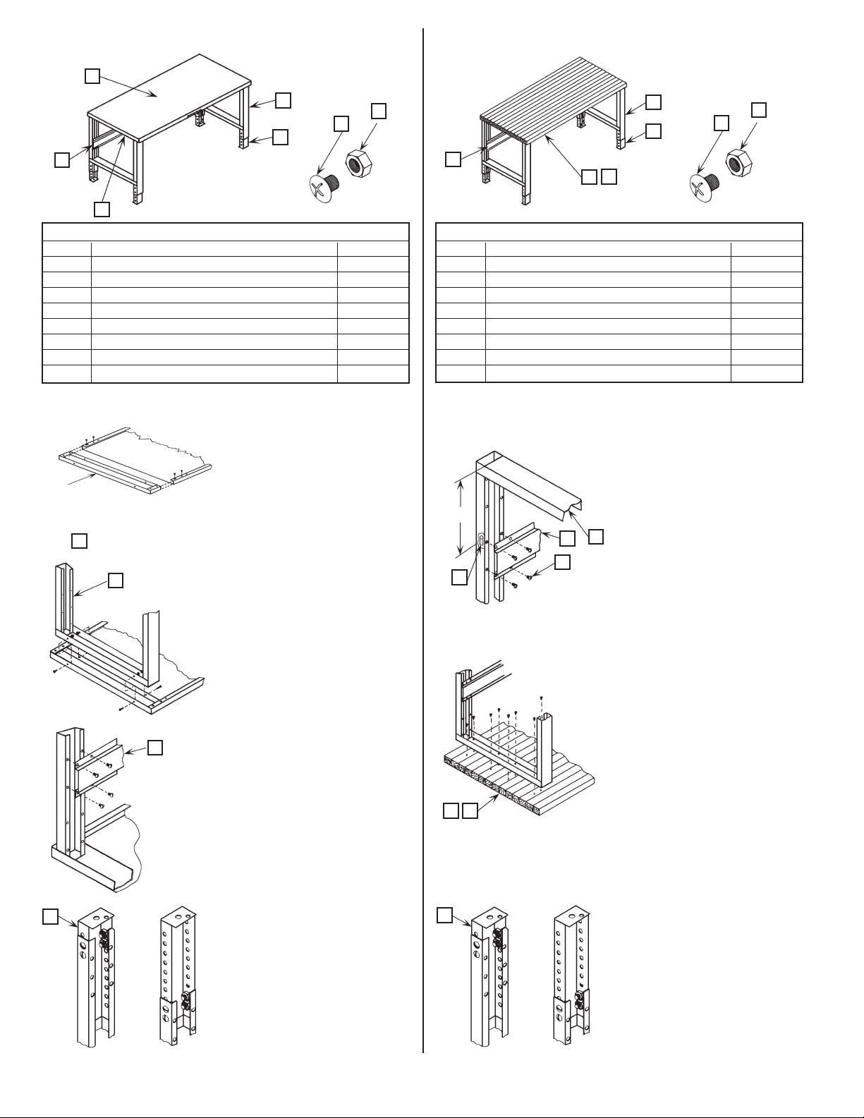
Parts List "A"
Item Description Req'd.
1 Bench Top 1
2 Stringer 1
3 Leg Attachment Channel 2
4 Leg Weldment 2
5 Adjustable Foot 4
6 .312 (5/16) - 18 x .500 (1/2) Phillips T.H.M.S. 40
7 .312 (5/16) - 18 Keps Nut 32
8 .312 (5/16) - 18 Weldnut 8
Tools Required: 1. Phillips Screwdriver
2. 1/2" Open End or Box Type Wrench
1. Lay bench top (Item 1) upside down
on a at surface.
2. Insert leg attachment channel (Item
3) into bench top with the open area
3
FIGURE 1
4
FIGURE 2
2
FIGURE 3
5
FIGURE 4
of channel facing upward. Position
attachment channel so that the
holes in the end anges are in line
with the oval and rst hole in the
front and back anges of the bench
top. Fasten channel to bench top
with (4) screws and nuts (Items 6
& 7) as provided in this hardware
pack. See Figure 1. Repeat procedure
at the other end.
3. Stand leg weldment (Item 4) in
place. (Leg fits inside attachment
channel). Position leg so that holes
in the sides of the leg weldment are
in line with the holes in the sides of
the attachment channel. Loosely
fasten leg and channel together with
(4) screws and nuts (Items 6 & 7) as
provided. See Figure 2. Repeat
procedure at the other end.
4. The stringer (Item 2) is to be attached
so the legs along the back edges of
bench. Position stringer so that the
holes in the end of the stringer are
in line with the holes in the leg.
Fasten stringer to leg with (4) screws
and weldnuts (Items 6 & 8) as
provided. See Figure 3. Repeat
procedure at the other end.
Tighten screws holding leg
weldments and attachment
channels together.
5. Insert adjustable foot (Item 5) into
leg so that the holes in the sides
of the foot are aligned with the
holes in the sides of the leg. At the
desired height, fasten foot to leg
with (4) screws and nuts (Items 6 &
7) as provided. See Figure 4. Repeat
procedure for the other legs.
Parts List "B"
Item Description Req'd.
1 Maple Wood Top 1
2 Multi-Duty Wood Top 1
3 Stringer 1
4 Leg Weldment 2
5 Adjustable Foot 4
6 .312 (5/16) - 18 x .500 (1/2) Phillips T.H.M.S. 24
7 .312 (5/16) - 18 Keps Nut 16
8 .312 (5/16) - 18 Weldnut 8
Tools Required: 1. Drill with 1/4" Drill Bit
2. Phillips Screwdriver
3. 1/2" Open End or Box Type Wrench
1. The stringer (Item 3) is to be attached
to the leg weldment (Item 4). Position the stringer so that the holes
in the end of the stringer are in line
with the holes in the legs; located
11-
5
4
3
6
8
FIGURE 5
21
FIGURE 6
FIGURE 7
approximately 11-5/8" down from
the top of the leg weldment. Fasten
the stringer to the leg with (4) screws
and weldnuts (Items 6 & 8) as provided. See Figure 5. Repeat procedure
at the other end.
2. Lay bench top (Item 1 or 2) upside
down on a at surface.
3. Place the leg weldment and stringer
assembly upside down on the bench
top. The stringer should be placed
toward the back edge of the bench
top. Position the leg weldment and
stringer assembly so it is centered
on the bench top and the legs are
parallel to the ends of the bench.
Use the leg weldments as templates
and drill (8) 1/4" pilot holes x 1" deep
for the lag screws at each end of the
bench top. Fasten the leg weldment
and stringer assembly to the bench
top with (8) .312 (5/16") x 1" lag
screws. See Figure 6. Lag screws are
not furnished by manufacturer.
4. Insert adjustable foot (item 5) into
leg so that the holes in the sides
of the foot are aligned with the
holes in the sides of the leg. At the
desired height, fasten foot to leg
with (4) screws and nuts (Items 6 &
7) as provided. See Figure 7. Repeat
procedure for the other three legs.
This completes assembly of the Work
Bench with an All-Wood Top. Put bench
in upright position.
Page 3
Page 4
End Guards
Parts List "E"
Item Description Req'd.
1 End Guard 1 pair
2 .312 (5/16) - 18 x .500 (1/2) Phillips T.H.M.S. 4
3 .312 (5/16) - 18 Keps Nut 4
Tools Required: 1. Phillips Screwdriver
2. 1/2" Open End or Box Type Wrench
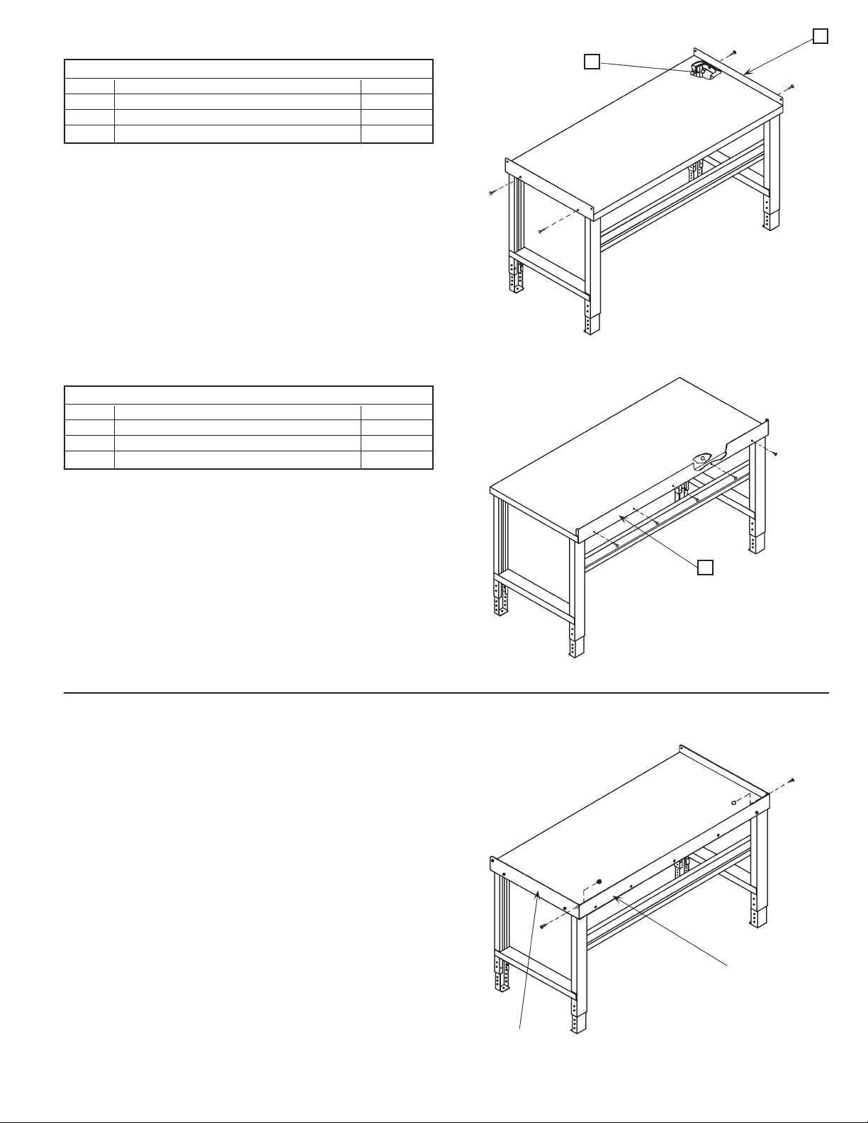
Position end guard (Item 1) so that the two holes align with the
holes in the side of the attachment channel. Fasten end guard
to channel with (2) screws and nuts (Items 2 & 3) as provided.
Repeat procedure at the other end.
This completes the End Guard assembly.
Back Guard
Parts List "F"
Item Description Req'd.
1 Back Guard 1
2 .312 (5/16) - 18 x .500 (1/2) Phillips T.H.M.S. 7
3 .312 (5/16) - 18 Keps Nut 7
1
3
Tools Required: 1. Phillips Screwdriver
2. 1/2" Open End or Box Type Wrench
Position back guard (item 1) so that the ovals in the lower edge of
the back guard are in line with the holes in the back edge of the
bench top. (Flanges on the back guard are to be facing toward
the front). Fasten back guard to bench top with (5) screws and
nuts (Items 2 & 3) as provided.
This completes the Back Guard assembly.
NOTE: The extra (2) screws and nuts are used when the end
guards and back guard are combined on the work bench.
End Guards and Back Guard Combined
Attach end guards and back guard to work bench as stated in the
separate assemblies for the end guards and back guard above.
Flanges on back guard are to be located inside of the end guards.
Fasten end guards to back guard with (1) screw and nut (Items 2
& 3) as provided, at each corner.
This completes the assembly for the End Guards and Back Guard
Combined.
~
1
~
~
END GUARD
(1 pr. required)
BACK GUARD
Page 5
Ledge Riser
Parts List "G"
Item Description Req'd.
1 Ledge Shelf 1
2 Ledge End 2
3 .312 (5/16) - 18 x .500 (1/2) Phillips T.H.M.S. 10
4 .312 (5/16) - 18 Keps Nut 10
Tools Required: 1. Phillips Screwdriver
2. 1/2" Open End or Box Type Wrench
4
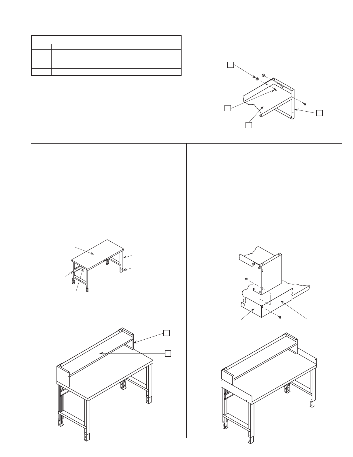
1. Place the end of the ledge shelf (Item 1) in between the
anges of the ledge end (Item 2). The two holes on the back
of the shelf must align with the top two ovals on the rear
ange of the ledge end. Align the hole in the front ange
of the ledge shelf with the top hole on the front ange of
the ledge end. Fasten the ledge shelf to the ledge end with
(3) screws and nuts (Items 3 & 4) as provided. See Figure 14.
Ledge Riser for Work Bench Without
End Guards and Back Guard
1. Place the ledge assembly on the bench top so that the rear anges
and sides of the ledge ends are ush with the back and sides of the
bench top. Mark the location of the two holes of the bottom ange
of the ledge end, on the bench top, at each end. Remove the ledge
assembly and drill (2) .344 (11/32") dia. holes at the marked locations
at each end of the bench top. Reposition the ledge assembly so that
the holes in the bottom anges of the ledge ends align with the drilled
holes. Fasten the ledge assembly to the bench top with (4) screws and
nuts (Items 3 & 4) as provided, two at each end. See Figure 15.
This completes the assembly of the Ledge Riser for the Work Bench Without
End Guards and Back Guard.
3
~
2
1
FIGURE 14
Ledge Riser for Work Bench With
End Guards and Back Guard
1. Place the ledge assembly on the bench top ush against the end
guards and/or back guard. The bottom oval in the sides of the ledge
ends must align with the hole in the back corner of the end guards
and/or the hole in the end anges of the back guard. Fasten the ledge
assembly to the end guards and/or back guard with (1) screw and nut
(Items 3 & 4) as provided. See Figure 16. If both end guards and a back
guard are on the work bench, remove the hardware holding the two
pieces together at each rear corner. Position the ledge assembly to
align with the holes in the guards as stated in the beginning of this
step, and fasten the ledge assembly to the guards with the hardware
originally provided.
This completes the assembly of the Ledge Riser for the Work Bench Without
End Guards and Back Guard.
BENCH TOP
~
FIGURE 15
~
~
~
END GUARD
BACK GUARD
2
1
FIGURE 16
Page 6
Portable Bench
Parts List "H"
Item Description Req'd.
1 Heavy Duty Plate 4
2 Caster 2
3 Caster with Brake 2
4 .438 (7/16) Helical Lock Washer 2
5 .438 (7/16) - 14 Hex Nut 2
Tools Required: 1. 5/8" Open End or Box Type Wrench
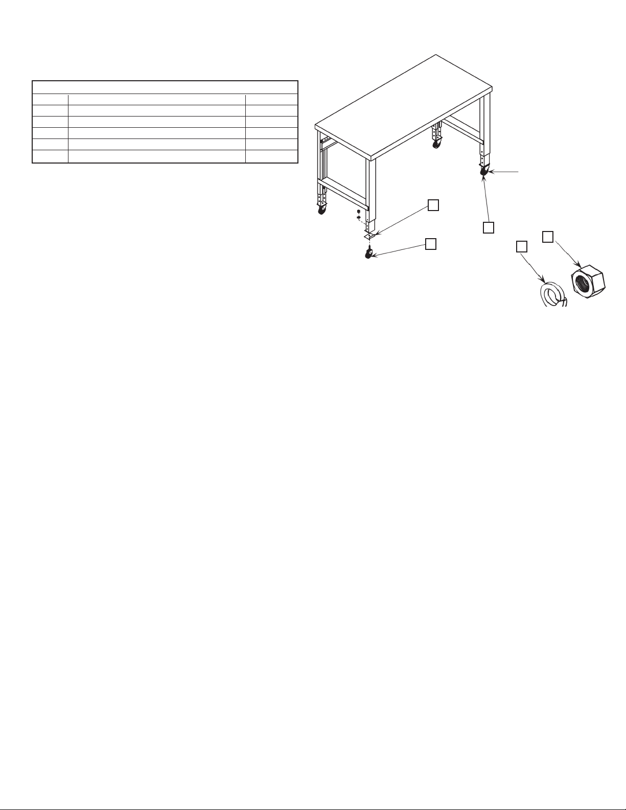
1. Place the work bench upside down on a at surface.
2. Position the heavy duty plate (Item 1) on the adjustable foot. The ange on
the heavy duty plate is to be placed along the front edge of the adjustable
foot. Insert the threaded stem of the caster (Items 2 & 3) through the holes
in the heavy duty plate and the adjustable foot. Fasten the three items together with (1) washer and nut (Item 4 & 5) as provided. Repeat procedure
with the other three adjustable feet.
3. Adjust bench to desired height. Place unit in upright position.
NOTE: Both of
the casters with
the brakes are to
1
3
2
be placed on the
same end of the
work bench.
5
4
LIMITED LIFETIME WARRANTY
We extend to the original purchaser from the date of purchase a lifetime limited warranty against manufacturing defects in material and workmanship. If a our product fails to perform
because of a manufacturing defect, we will examine it. If found defective, it will be repaired or replaced at our option. This warranty applies only to our products acquired directly from us or
from our Authorized Dealers. This warranty does not apply to any product which has been subject to misuse, negligence, or accident; has been damaged in shipment, storage, or
installation; has been misapplied or has been modified or repaired by unauthorized persons or been repaired with non-standard our replacement parts. This warranty specifically excludes
claims for indirect, incidental, or consequential damages arising in any way from a product defect. This warranty is exclusive, and exists in lieu of all other warranties, either expressed or
implied. This warranty gives you specific legal rights; you may also have other rights which may vary from state to state. Contact Selling Dealer, to obtain warranty service. You must make a
written claim. Provide a copy of your purchase record and a written description of the warranty problem with your claim.
 Loading...