

Page 1
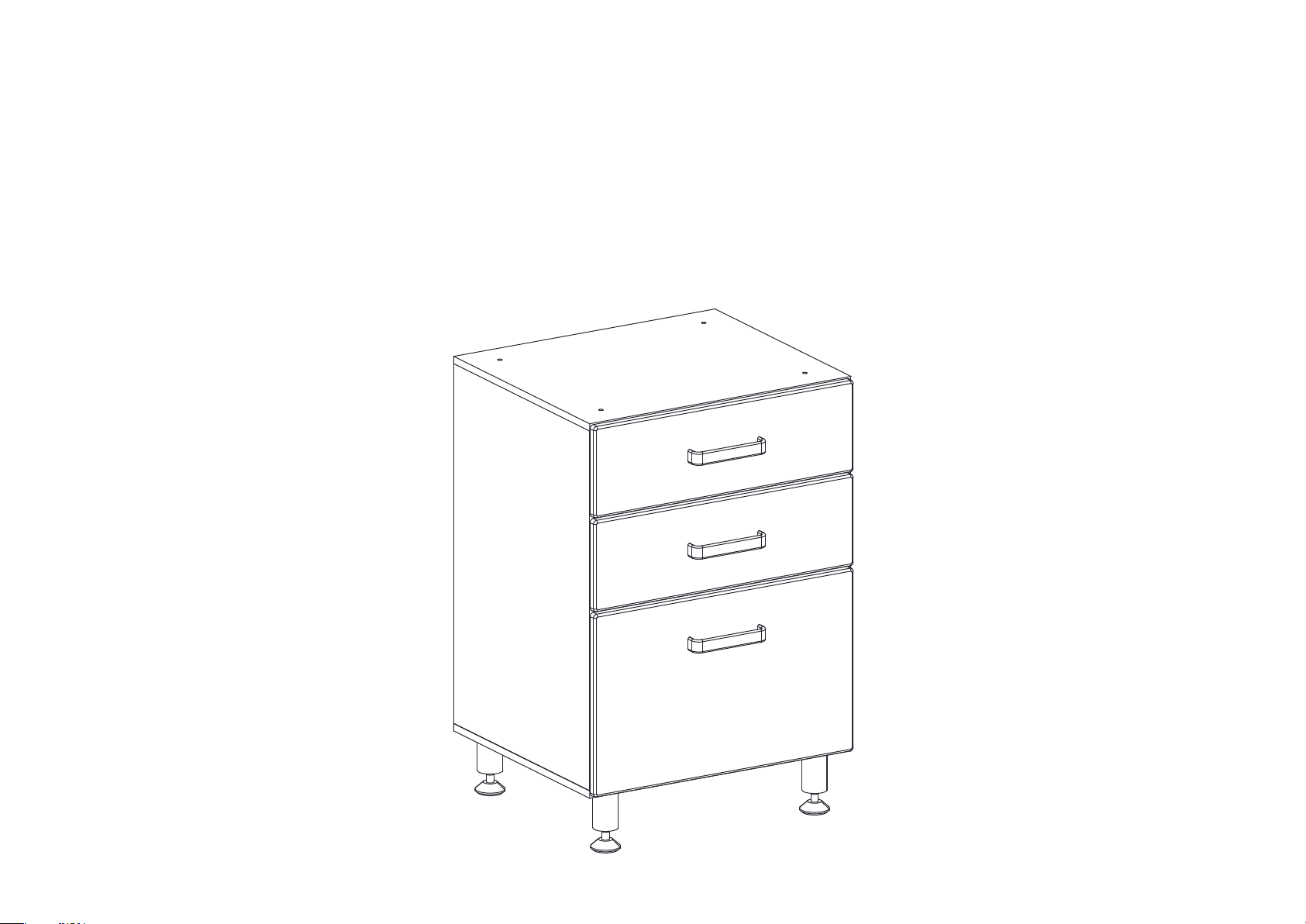
INSTALLATION AND ASSEMBLY
Page 2
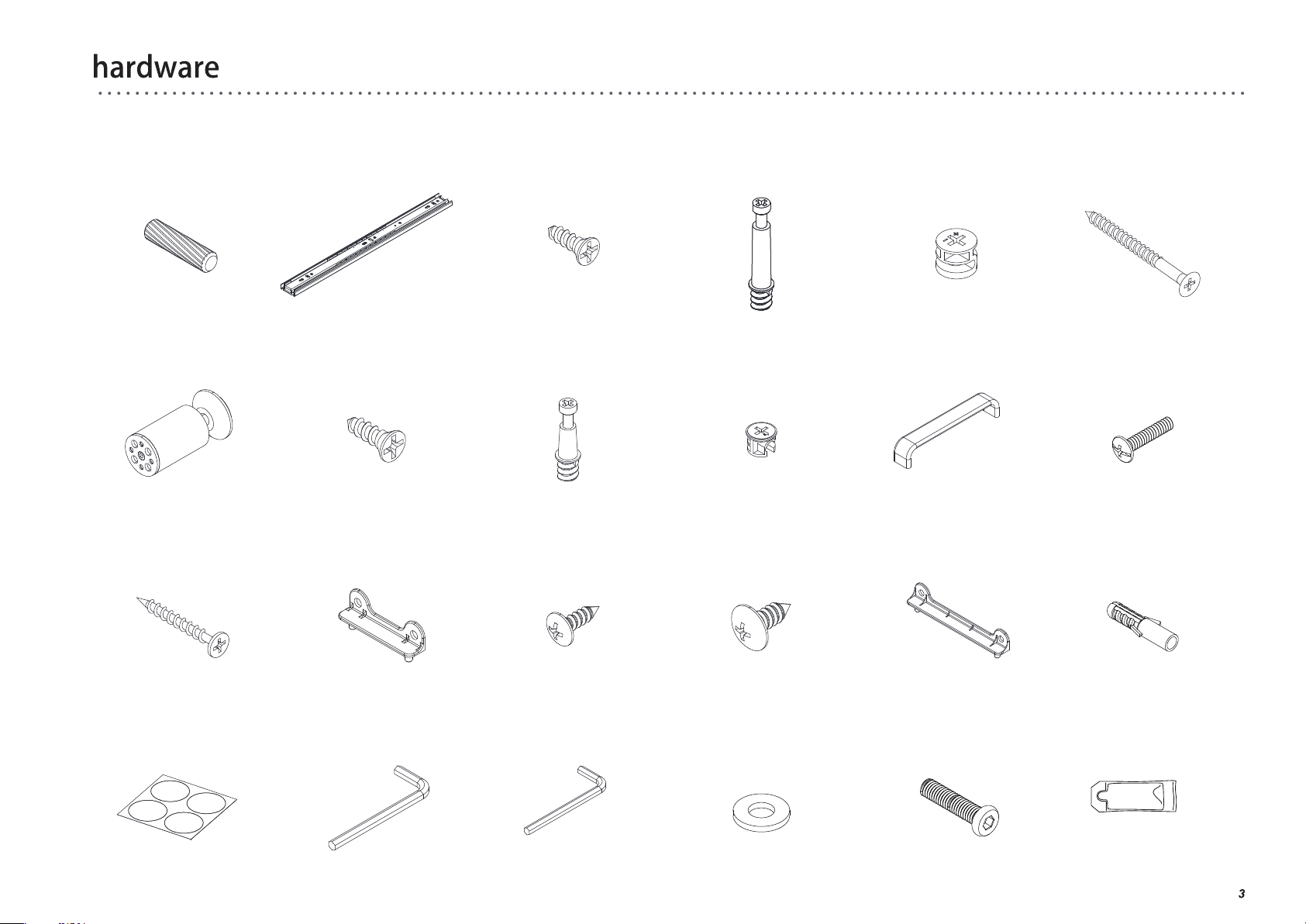
(Q) x 12
Wood dowel
Ø7.8 X 30mm
(R) x 6
Slider
(S) x 36
Screw Ø3.5 X 12mm
(T) x 6
Cam bolt
(large)
(U) x 6
Cam (large)
(V) x 6
Screw Ø5 X 50mm
(W) x 4
Adjustable leg
(Cc) x 15
Screw Ø3.8 X 35mm
(Ii) x 4
PVC cover
(X) x 16
Screw Ø4 X 16mm
(Dd) x 4
Drawer connector (small)
(Jj) x 1
Allen key M5
(Y) x 3
Cam bolt (small)
(Ee) x 34
Screw Ø3.5 X 12mm
(Kk) x 1
Allen key M4
(Z) x 3
Cam (small)
(Ff) x 12
Screw Ø4.7 X 12.5mm
(Ll) x 4
Metal washer
(Aa) x 3
Handle
(Gg) x 2
Drawer connector (large)
(Mm) x 4
Bolt M6 X 28mm
(Bb) x 6
Bolt M4 X 20mm
(Hh) x 2
Wall anchor
(Nn) x 1
Glue
Page 3
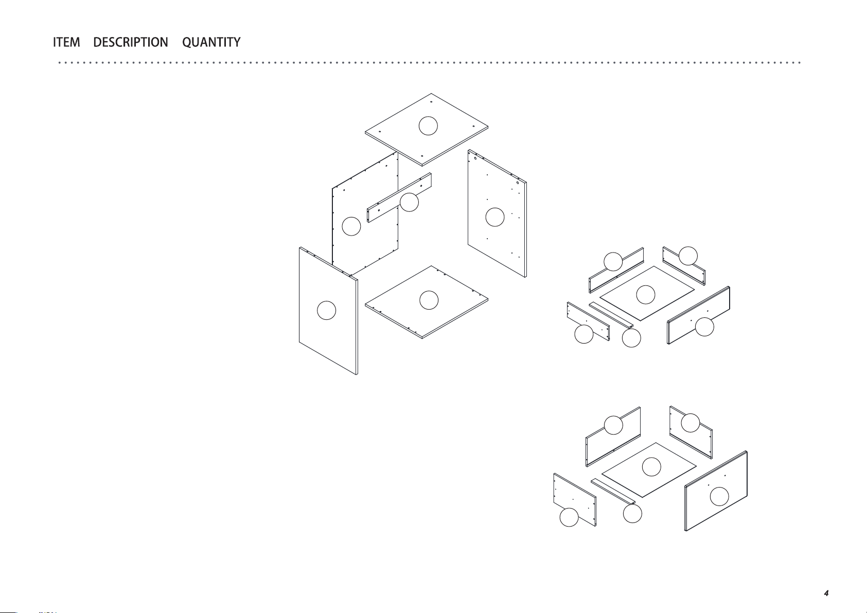
A
B
C
D
E
F
G
H
I
J
K
L
M
N
O
P
Q
R
S
T
U
V
W
X
Y
Z
Aa
Bb
Cc
Dd
Ee
Ff
Gg
Hh
Ii
Jj
Kk
Ll
Mm
Nn
Back rail
Left side panel
Right side panel
Top
Bottom
Back panel
Left drawer side
Right drawer side
Drawer face
Drawer back
Drawer bottom support
Drawer bottom
Left drawer side
Right drawer side
Drawer face
Drawer back
Wood dowelØ7.8 X 30mm
Slider
Screw Ø3.5 X 12mm
Cam bolt (large)
Cam (large)
Screw Ø5 X 50mm
Adjustable leg
Screw Ø4 X 16mm
Cam bolt (small)
Cam (small)
Handle
Bolt M4 X 20mm
Screw Ø3.8 X 35mm
Drawer connector (small)
Screw Ø3.5 X 12mm
Screw Ø4.7 X 12.5mm
Drawer connector (large)
Wall anchor
PVC cover
Allen key M5
Allen key M4
Metal washer
Bolt M6 X 28mm
Glue
1
1
1
1
1
1
2
2
2
2
3
3
1
1
1
1
12
6
36
6
6
6
4
16
3
3
3
6
15
4
34
12
2
2
4
1
1
4
4
1
B
D
A
C
F
J
E
G
L
K
P
H
N
x 2
I
I
I
L
O
M
K
Page 4
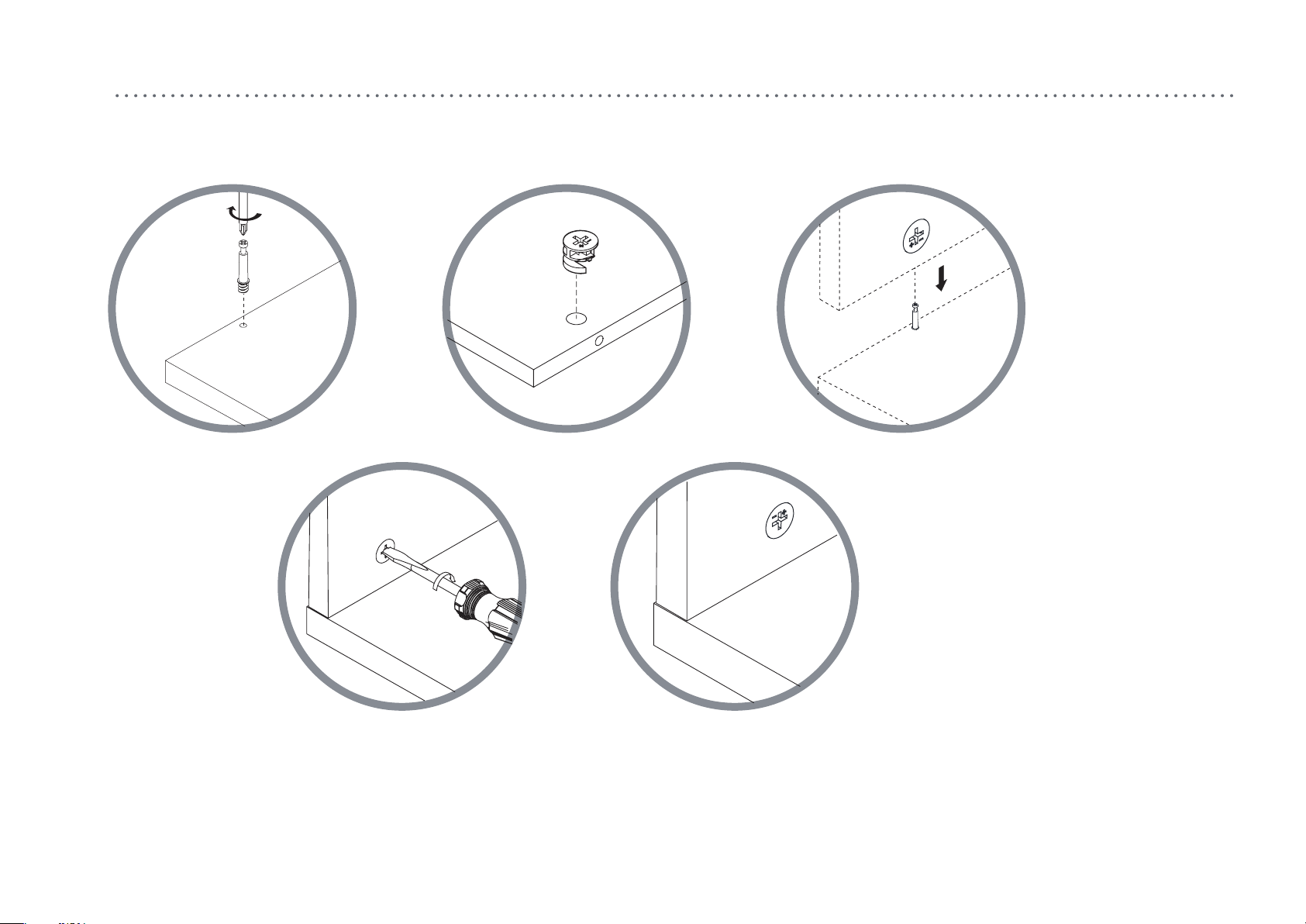
how to use the cam lock system
1. 2. 3.
160°~185°
4. 5.
5
Page 5
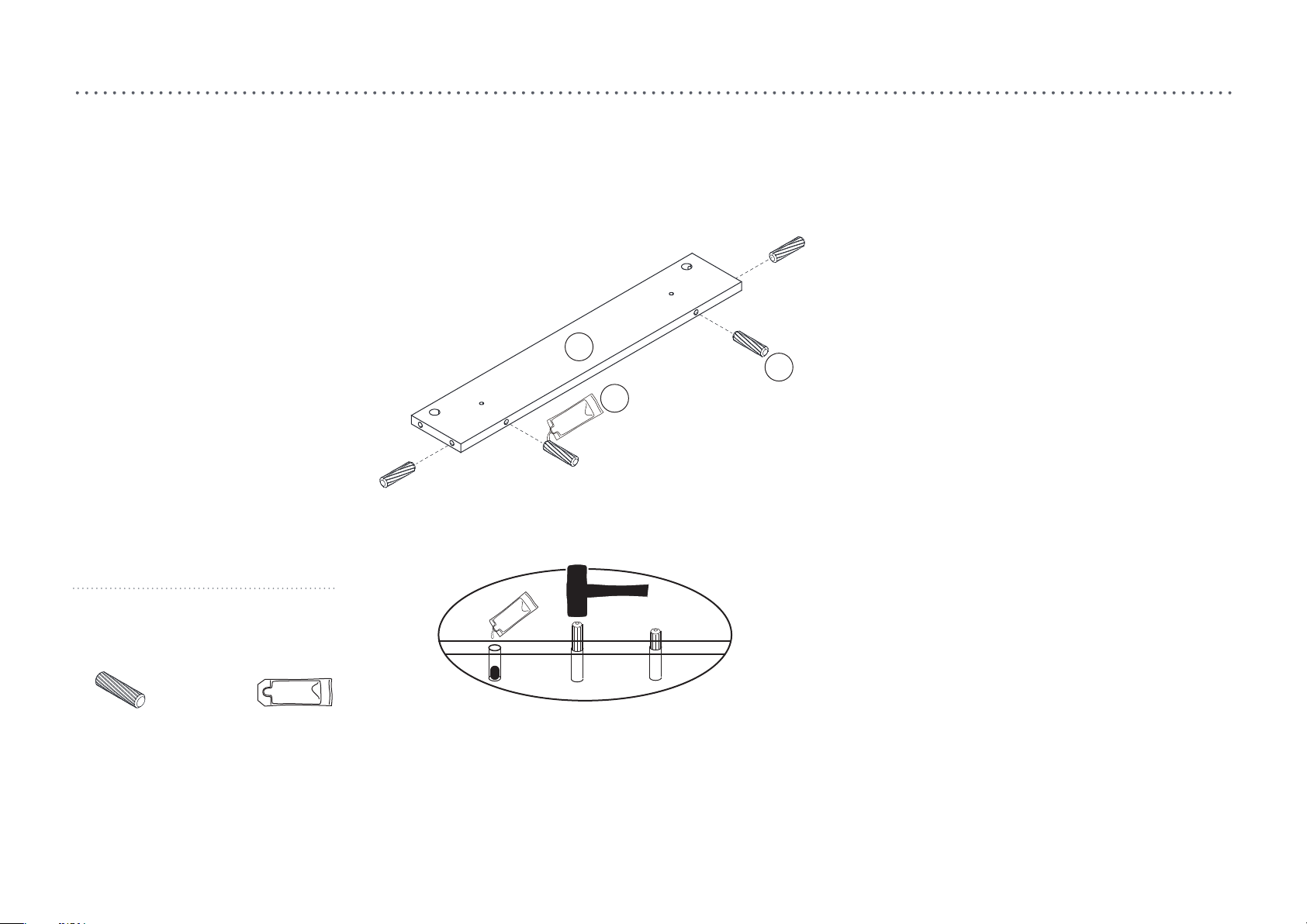
step 1.
A
Q
Nn
(Q) x 4
Wood dowel
Ø7.8 X 30mm
1. Instill the glue (Nn) to the wood dowel hole as image shown.
2. Insert the wood dowel (Q) to the part (A).
(Nn)
Glue
6
Page 6
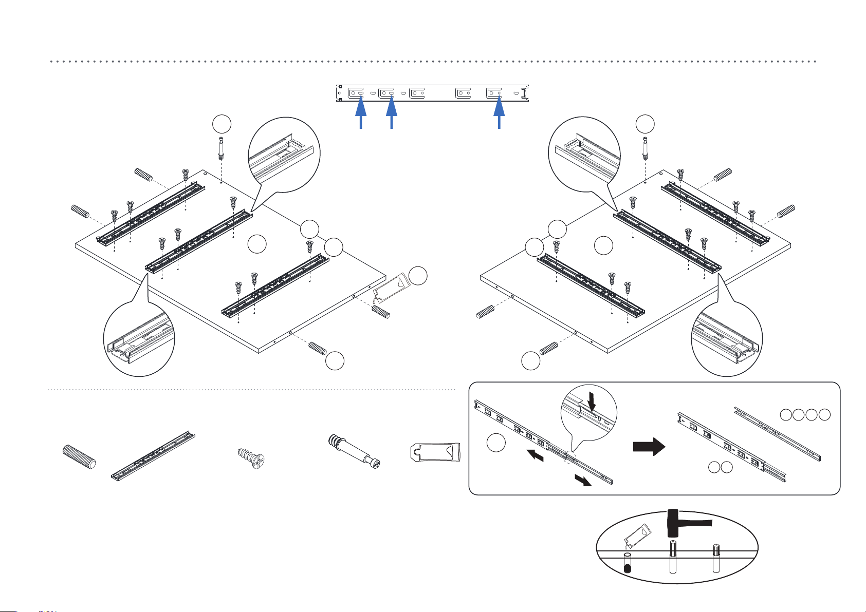
step 2.
T T
S
B
R R
Nn
Q Q
(Q) x 8
Wood dowel
Ø7.8 X 30mm
1. Instill the glue (Nn) to the wood dowel hole as image shown.
2. Insert the wood dowel (Q) to the part (B) and (C).
3. Attach the cam bolt (T) to the part (B) and (C).
4. Split the slider (R) as image shown. Attach the slider to the part with screw (S).
(R) x 6
Slider
(S) x 18
Screw Ø3.5 X 12mm
(T) x 2
Cam bolt
(large)
(Nn)
Glue
R
S
C
C
B
(for )
N
HG
(for )
M
7
Page 7
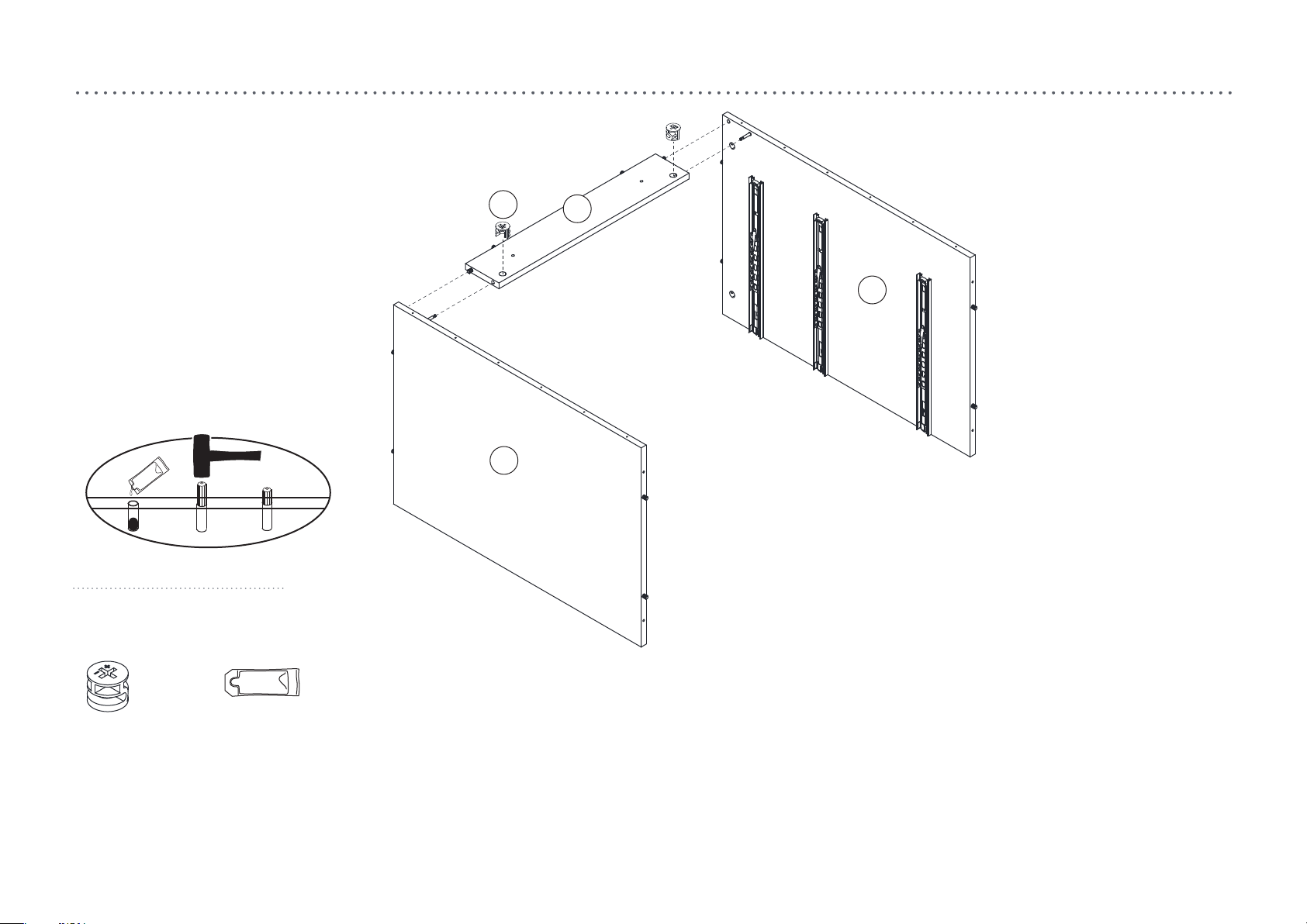
step 3.
(U) x 2
(large)
Cam
(Nn)
Glue
U
C
A
B
1. Instill the glue (Nn) to the wood dowel hole as image shown.
2. Attach the part (B) and (C) to part (A) using the wood dowel (Q) and cam bolt (T).
3. Tighten the part (A) using cam (U) as image shown.
8
Page 8
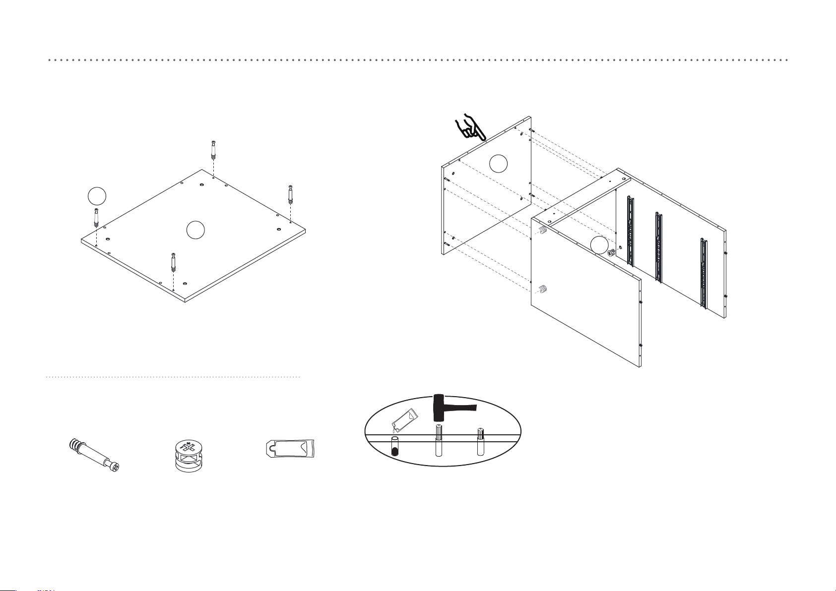
step 4.
T
D
D
U
(T) x 4
Cam bolt
1. Attach the cam bolt (T) to the part (D).
2. Instill the glue (Nn) to the wood dowel hole as image shown.
3. Attach the part (D) to the assembled parts using wood dowel (Q) and cam bolt (T). Take notice on the direction of the part (D).
(large)
(U) x 4
Cam
(large)
(Nn)
Glue
9
Page 9
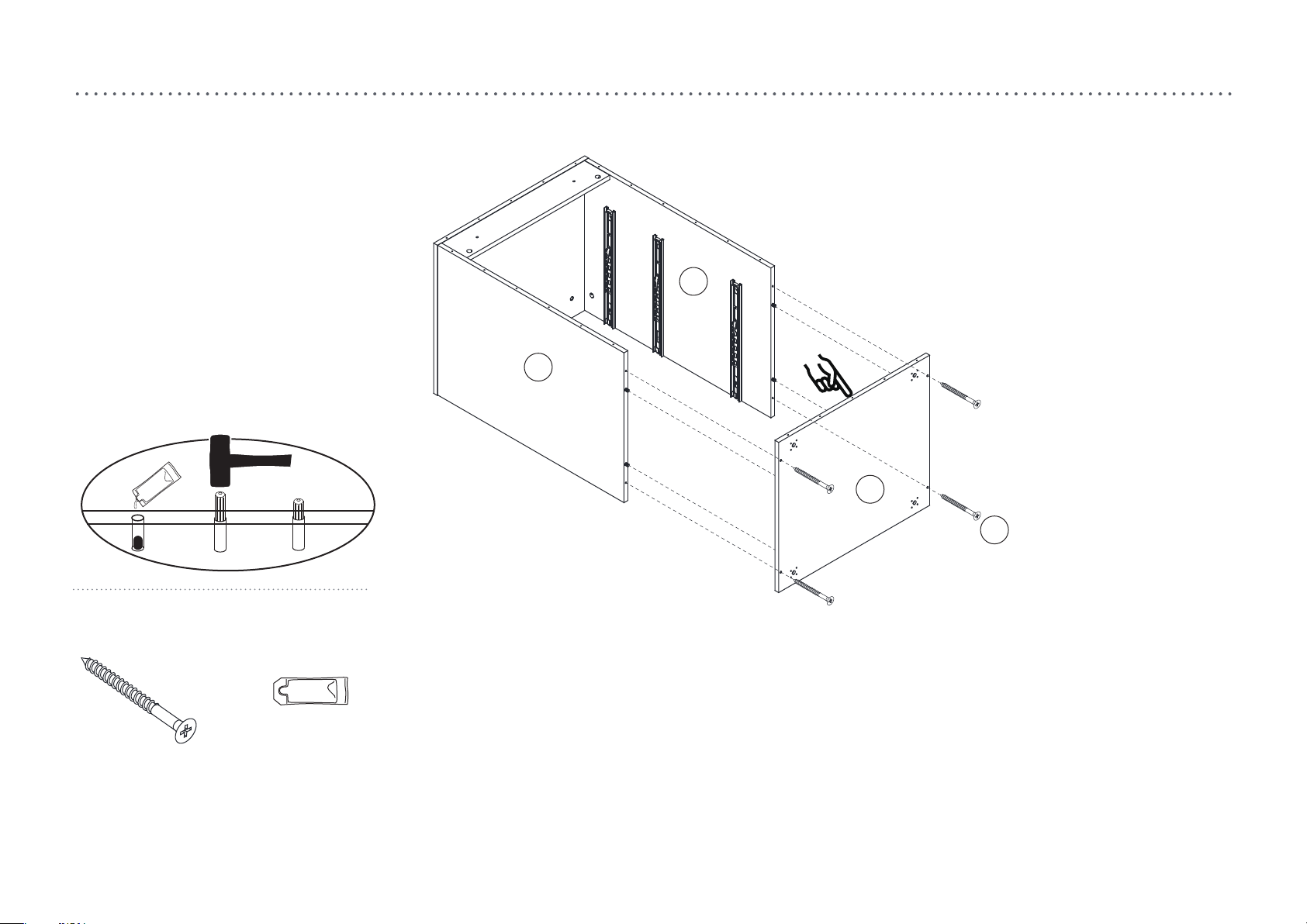
step 5.
B
C
E
(V) x 4
Screw Ø5 X 50mm
1. Instill the glue (Nn) to the wood dowel hole as image shown.
2. Attach the parts (B), (C) and (E) using screw (V).
(Nn)
Glue
V
10
Page 10
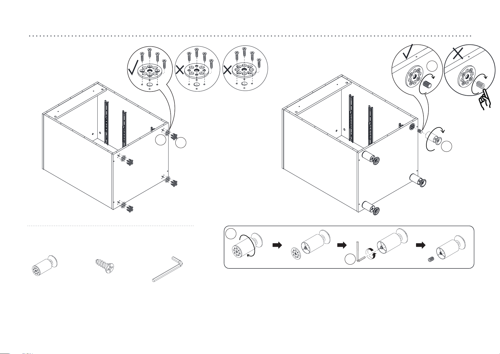
step 6.
W
W
(W) x 4
Adjustable leg
1. Knock down the adjustable leg (W) as image shown.
2. Attached the metal plate to the part (E) with screw (X), take notice on the metal plate screw hole.
3. Rotate the screw into the metal plate on part (E).
4. Attach the leg to the part (E) as image shown.
(X) x 16
Screw Ø4 X 16mm
(Jj) x 1
Allen key M5
X
W
W
Jj
11
Page 11
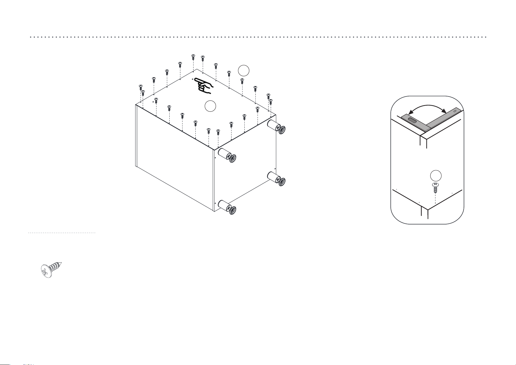
step 7.
Ee
F
°90
Ee
(Ee) x 22
Screw Ø3.5 X 12mm
1. Attach the back panel (F) to the body using screw (Ee).
Notice: Make sure the body angle should be in right angle before attach the back panel in.
And take notice on the back panel direction.
12
Page 12
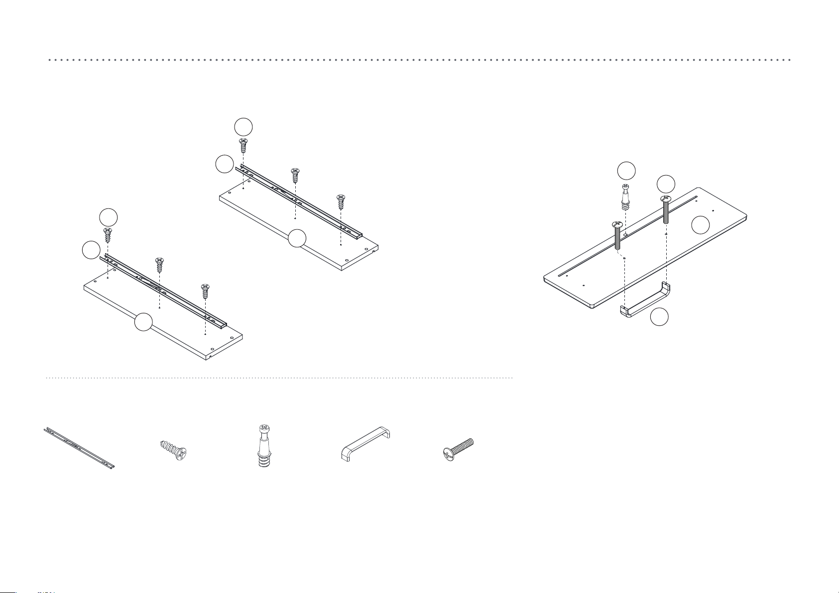
step 8.
x 2
S
(R) x 4
Slider
R
R
S
Y
Bb
I
I
I
H
G
(S) x 12
Screw Ø3.5 X 12mm
(Y) x 2
Cam bolt (small)
(Aa) x 2
Handle
(Bb) x 4
Bolt M4 X 20mm
Aa
1. Attach the slider (R) to the part (G) and (H) with screw (S).
2. Insert the cam bolt (Y) to the part (I).
3. Attach the handle (Aa) to the part (I) with screw (Bb).
13
Page 13
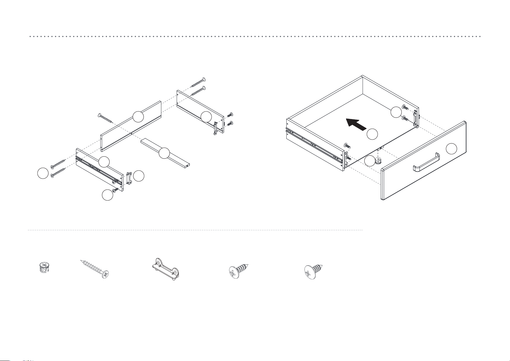
step 9.
x 2
Cc
(Z) x 2
Cam (small)
G
Ee
(Cc) x 10
Screw Ø3.8 X 35mm
J
K
Dd
(Dd) x 4
Drawer connector (small)
H
(Ee) x 8
Screw Ø3.5 X 12mm
(Ff) x 8
Screw Ø4.7 X 12.5mm
Z
Ff
L
I
I
I
1. Attach the drawer connector (Dd) to the part (G) and (H) with screw (Ee).
2. Attach the parts (G), (H), (J) and (K) together with screw (Cc).
3. Insert the part (L) to the groove of parts (G), (H) and (J).
4. Attach the part (I) to part (K). Make sure the part (L) inserted in the groove of part (I).
5. Tighten the part (I) with cam (Z).
6. Attach the drawer connector (Dd) to part (I) with screw (Ff).
14
Page 14
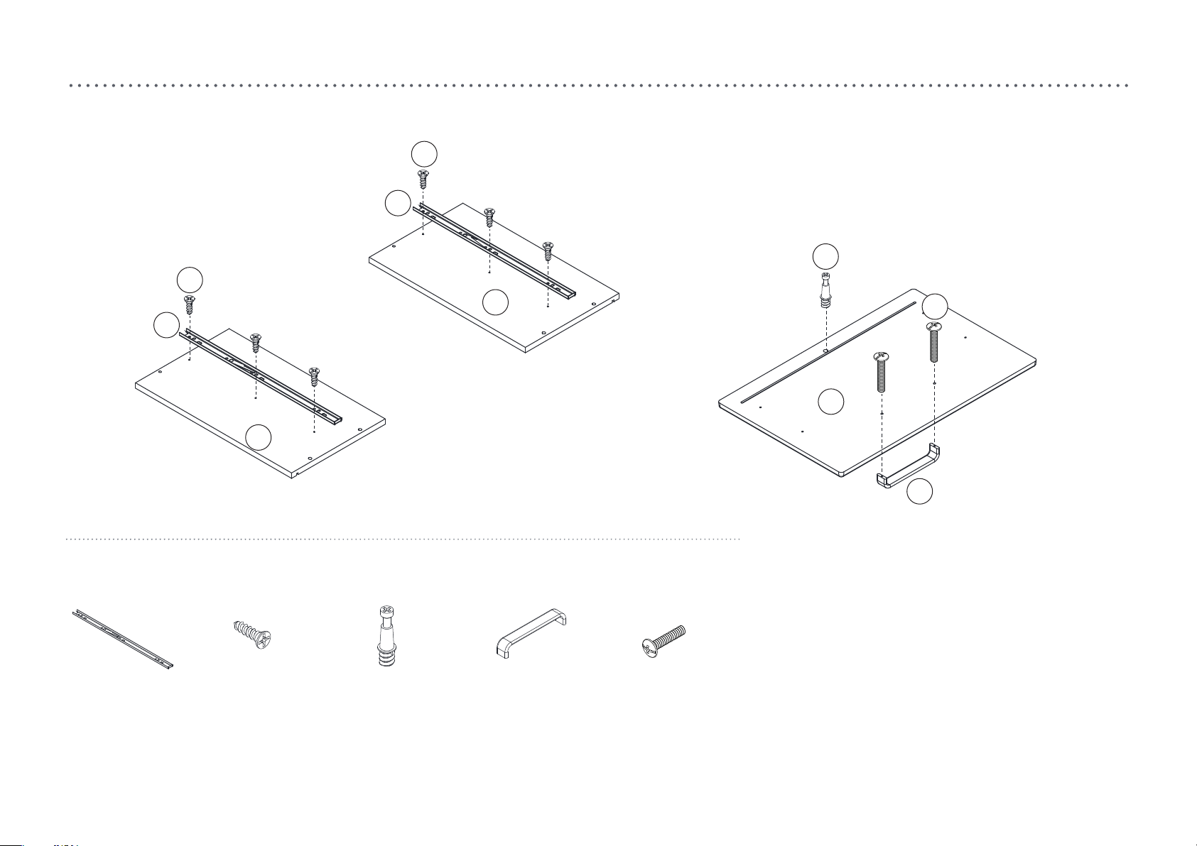
step 1.
step 10.
R
S
R
Y
S
N
Bb
O
M
(R) x 2
Slider
1. Attach the slider (R) to the part (M) and (N) with screw (S).
2. Insert the cam bolt (Y) to the part (O).
3. Attach the handle (Aa) to the part (O) with screw (Bb).
(S) x 6
Screw Ø3.5 X 12mm
(Y) x 1
Cam bolt (small)
(Aa) x 1
Handle
Aa
(Bb) x 2
Bolt M4 X 20mm
15
Page 15
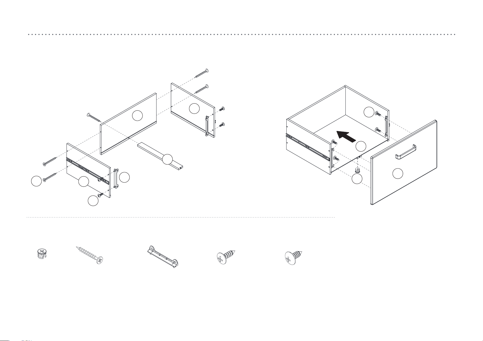
step 11.
Cc
(Z) x 1
Cam (small)
M
Gg
Ee
(Cc) x 5
Screw Ø3.8 X 35mm
N
P
K
(Gg) x 2
Drawer connector (large)
(Ee) x 4
Screw Ø3.5 X 12mm
Ff
L
O
Z
(Ff) x 4
Screw Ø4.7 X 12.5mm
1. Attach the drawer connector (Gg) to the part (M) and (N) with screw (Ee).
2. Attach the parts (M), (N), (P) and (K) together with screw (Cc).
3. Insert the part (L) to the groove of parts (M), (N) and (P).
4. Attach the part (O) to part (K). Make sure the part (L) inserted in the groove of part (O).
5. Tighten the part (O) with cam (Z).
6. Attach the drawer connector (Gg) to part (O) with screw (Ff).
16
Page 16
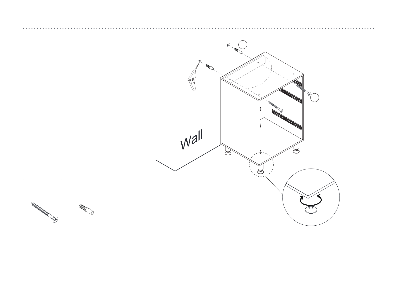
step 12.
Hh
V
(V) x 2
Screw Ø5 X 50mm
1. Mark the screw hole in the wall according to the product height.
2. Drill the hole in the wall using drill Ø8.
3. Knock the wall anchor (Hh) into the hole.
4. Attach the screw (V) to the wall anchor (Hh) through the product screw hole.
Notice: You could adjust the adjustable leg if the floor is not flat.
(Hh) x 2
Wall anchor
17
Page 17
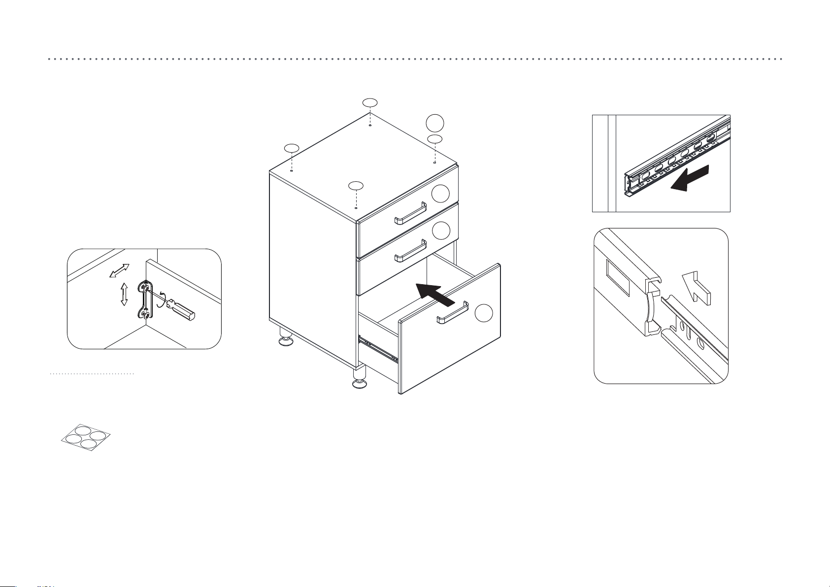
step 13.
Ii
I
I
I
I
I
I
O
(Ii) x 4
PVC cover
1. Cover the screw holes with PVC cover (Ii).
2.Install the drawers to the cabinet as image shown.
Please note a small degree of force may be necessary to get the slides to engage.
18
 Loading...